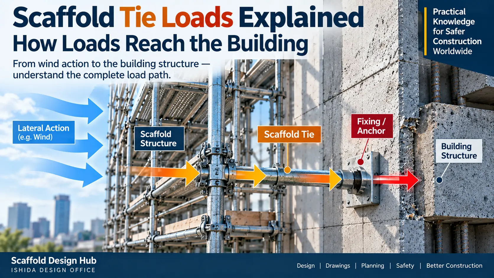
A scaffold tie does more than hold a scaffold close to a building. It forms part of a structural load path that transfers forces from the scaffold into a supporting structure.
That distinction matters.
A scaffold drawing may show a regular pattern of ties, but the presence of tie symbols does not prove that the forces acting on the scaffold can actually reach the building safely. The tie component, its connection to the scaffold, the fixing or anchor, the supporting substrate and the building structure all form part of the same load-transfer system.
For designers and reviewers, therefore, the important question is not simply:
“Where are the ties?”
It is:
“Where does the force go?”
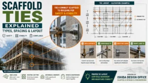
For an introduction to tie types and layout before considering the forces they must transfer, see Scaffold Ties Explained: Types, Spacing & Layout.
What Is a Scaffold Tie Load?
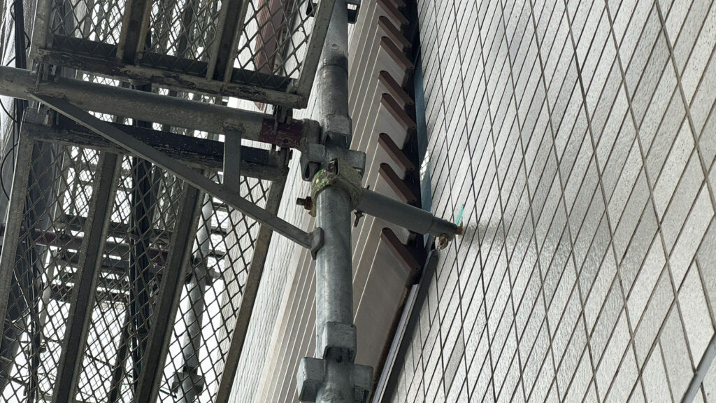
A scaffold tie load is the force that a tie connection must transfer between the scaffold and the supporting structure.
Depending on the scaffold configuration and the actions being considered, a tie may be required to resist forces acting toward or away from the building. The required tie performance therefore cannot be understood only from the physical presence of the tie.
Tie location and tie load are related, but they are not the same design question.
A drawing can answer:
Where is the tie intended to be installed?
Structural assessment must also answer:
What force is expected at that location, and can the complete connection resist and transfer it?
This is one reason why tie spacing should not automatically be treated as a fixed number that can be applied to every scaffold.
Where Do Scaffold Tie Loads Come From?
Several actions and design conditions can contribute to the forces that ultimately reach the ties.
One of the most important is wind.
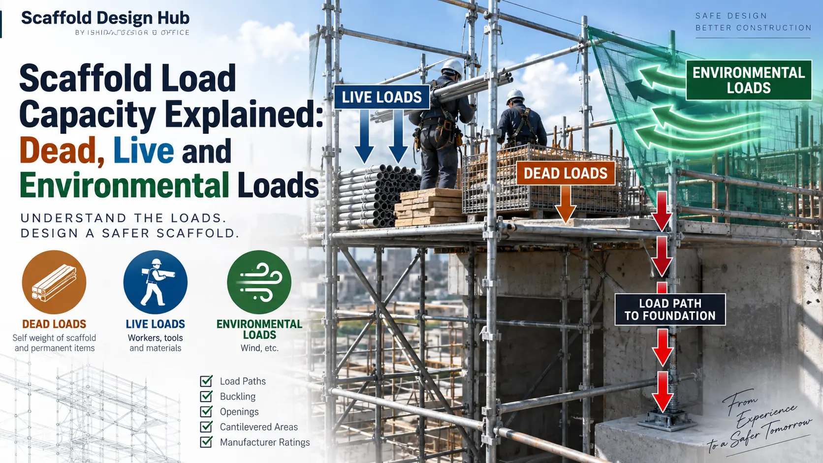
Wind acting on scaffold components, platforms, guardrails and especially enclosed surfaces can generate lateral forces. Those forces have to travel through the scaffold structure and ultimately be resisted by an appropriate stability system.
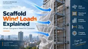
For a broader explanation of environmental actions, see Scaffold Wind Loads Explained: What Designers Need to Consider.
HSE guidance in Great Britain specifically warns against attaching sheeting or debris netting without informing those responsible for the scaffold’s design and erection, because the scaffold must be designed for the resulting condition.
Safe Work Australia guidance similarly identifies environmental loads such as wind among the loads that should be considered during scaffold design and includes screens and sheeting among scaffold dead-load components.
Scaffold Geometry and Configuration
Tie demand is also influenced by the geometry and configuration of the scaffold.
Height, lift arrangement, tie positions, scaffold width, projections, openings, corners and other irregular conditions can affect how forces move through the structure.
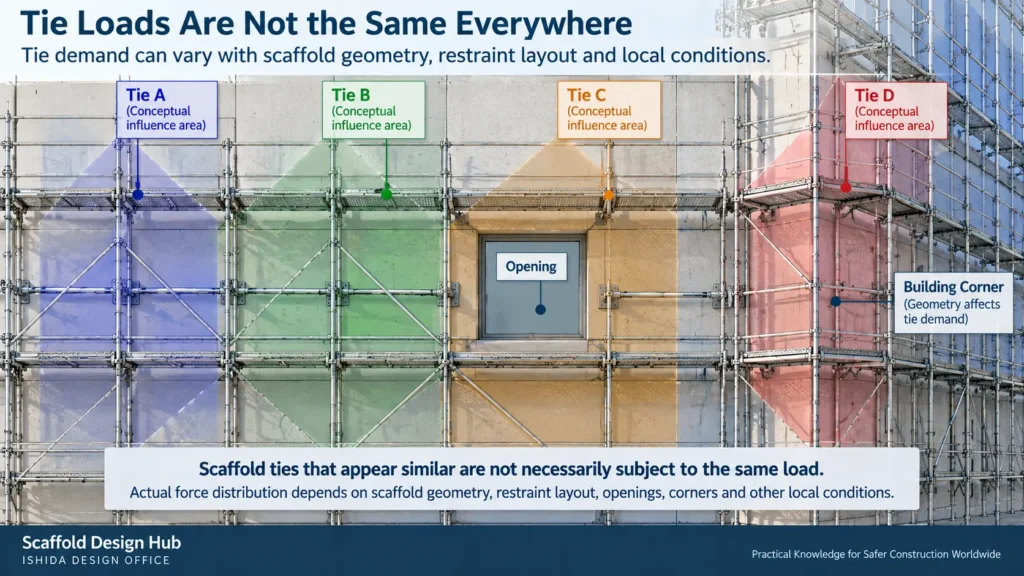
This is why two scaffolds that appear similar in elevation should not automatically be assumed to have identical tie-load conditions.
Sheeting, Netting and Enclosure Conditions
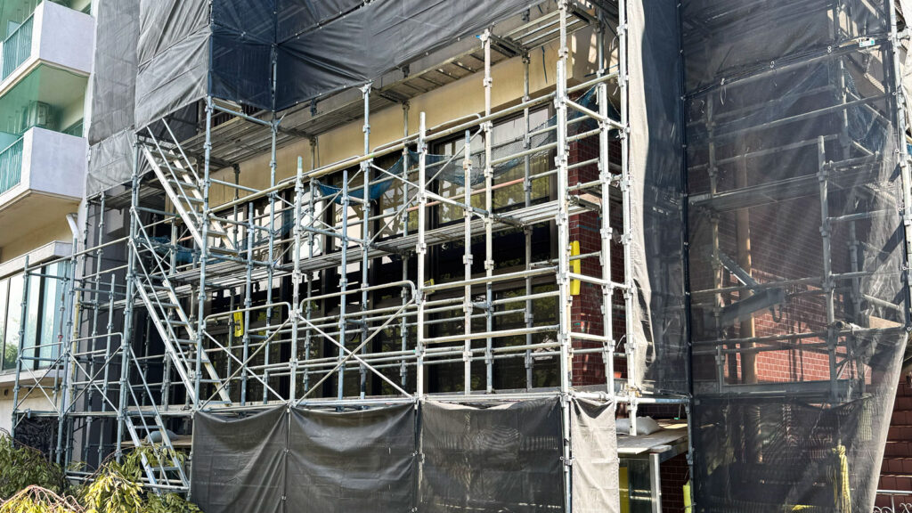
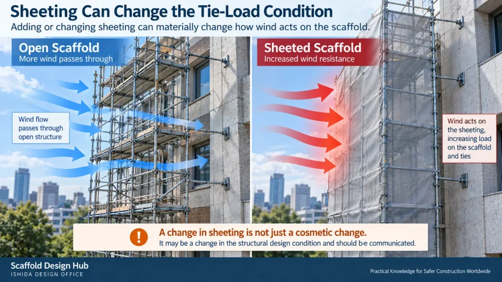
Sheeting can significantly change how wind interacts with a scaffold.
Adding sheeting, screens or netting can materially change how wind acts on the scaffold and therefore the loads that the scaffold stability system must resist.
HSE also notes, in its guidance for scaffolds used during alteration, demolition and dismantling, that sheeting increases the effect of wind on the scaffold and the load applied to the building.
IMPORTANT: A change in sheeting should not automatically be treated as a cosmetic site change. It may be a change in the structural design condition.
How Loads Travel from the Scaffold to the Building
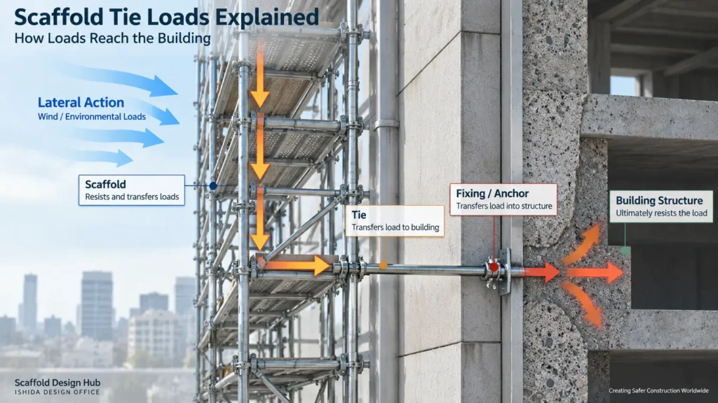
Thinking in terms of a load path is one of the clearest ways to understand scaffold tie loads.
Applied lateral action → scaffold structure → tie connection → fixing or anchor → supporting building structure
Each stage matters.
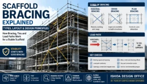
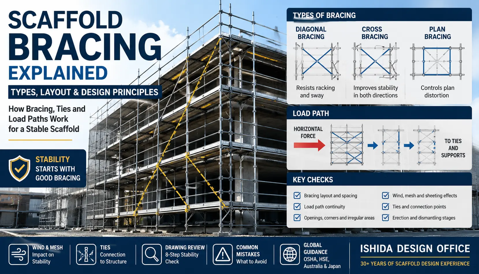
For the broader structural context, Scaffold Stability Explained: How Bracing, Ties and Bases Work Together explains how the main stability components interact.
Step 1 — Load Acts on the Scaffold
Consider wind as an example.
Wind acts on the exposed scaffold and any attached enclosure. The resulting force does not appear directly at a single tie. It first acts on the exposed parts of the scaffold.
Step 2 — Scaffold Members Distribute the Force
The scaffold system transfers and distributes these forces through its standards, ledgers, transoms, bracing and other connected components.
The precise distribution depends on the scaffold system and its structural configuration.
This article deliberately does not provide a universal calculation formula because the appropriate analysis depends on the system, design method, applicable standards, manufacturer information and project conditions.
Step 3 — Force Reaches the Tie
The tie forms part of the restraint system connecting the scaffold to the supporting structure.
Its demand depends on the forces reaching that tie location and on how the overall restraint arrangement distributes those forces.
This is why changing the tie arrangement can change the structural behaviour.
Step 4 — The Tie Transfers Force Through the Fixing
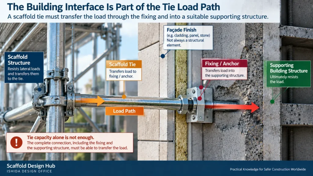
The load path does not end at the end of the scaffold tie.
The connection to the building must also transfer the force.
Depending on the project, that interface may involve an anchor, structural member or another specifically designed connection.
The capacity of the tie component alone therefore does not establish the capacity of the complete tie system.
In my scaffold design work, one of the first things I check is the allowable capacity of the proposed anchor and whether the tie can actually be installed at the intended location. If it cannot, I consider alternative restraint arrangements, subject to verification of the required forces, complete load path and supporting structure.
Step 5 — The Building Structure Receives the Load
Ultimately, the force must be transferred into a suitable part of the building or supporting structure.
This final stage is sometimes overlooked when a scaffold drawing concentrates mainly on the scaffold itself.
Key design-review question: What structural element is actually receiving this tie load?
If that question cannot be answered from the available information, the load path may need further investigation.
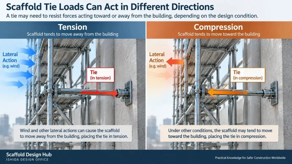
Tension and Compression in Scaffold Ties
A tie connection may experience forces acting in different directions as the scaffold responds to lateral actions.
Conceptually, the scaffold may tend to move away from the building under one condition and toward it under another. The tie arrangement and its connections therefore need to be appropriate for the forces they are intended to resist.
The important point for a general design review is not to assume that “a tie is a tie.”
The tie component, connections and supporting structure must be considered as a system, with capacities and installation requirements checked against the actual design condition.
Manufacturer documentation is particularly important because proprietary scaffold components should be used within the manufacturer’s stated requirements. HSE states that proprietary system scaffolds should be erected and tied according to manufacturers’ instructions.
Why Tie Loads Are Not the Same Everywhere
A common mistake is to imagine that every tie on an elevation automatically carries the same load.
Actual force distribution depends on the structural model and project conditions.
Tie Spacing and Tributary Area
Conceptually, a tie associated with a larger area of scaffold may be required to participate in resisting a greater portion of the lateral action than one associated with a smaller area.
However, tributary area alone should not be turned into a universal tie-load formula.
Scaffold geometry, stiffness, tie layout, bracing, boundary conditions, wind conditions and the particular scaffold system can all matter.
This article therefore treats tributary area as a useful concept for understanding load distribution—not as a substitute for project-specific structural assessment.
Corners, Ends and Irregular Geometry
Building corners and scaffold ends deserve particular attention.
In practical scaffold design work, ideal tie locations are not always available. Scaffold bay layout at corners can make the preferred connection position difficult to achieve.
The same problem can occur around façade changes, projections, openings and other irregular geometry.
This is where a regular tie pattern on paper can begin to diverge from what can actually be constructed.
The Top of the Scaffold
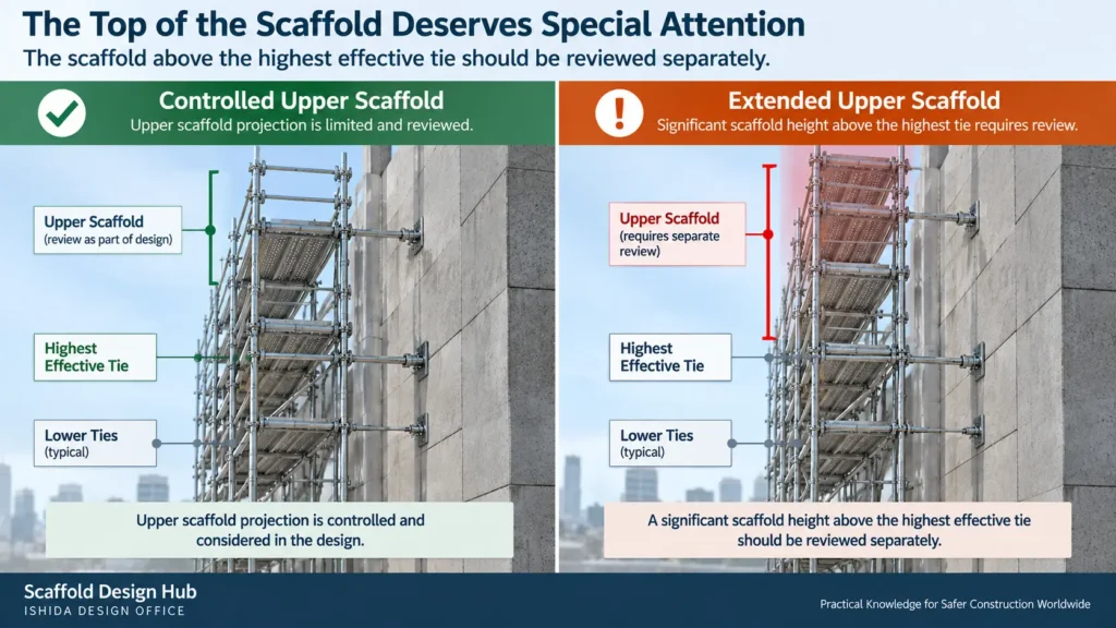
The upper part of a scaffold deserves specific review.
If the scaffold extends a significant distance above its highest effective restraint, the geometry of that upper section can become an important stability consideration.
OSHA’s U.S. supported-scaffold requirements illustrate this principle by limiting the permitted distance between the top restraint and the top of certain supported scaffolds within the conditions covered by 29 CFR 1926.451(c)(1). These are U.S.-specific requirements and should not be treated as universal international spacing rules.
In the author’s design experience, upper scaffold geometry is one of the conditions that deserves deliberate checking rather than assuming the regular tie arrangement below can simply continue unchanged.
Sheeting Can Change the Tie-Load Condition
One practical problem is that the scaffold specified during design may not be the scaffold that finally exists on site.
The enclosure is a good example.
The author has encountered situations where the type of sheet used on the scaffold was changed after planning, including substitutions driven by contractor stock availability, without the design side initially being aware of the change.
The important lesson is not the particular product that was substituted.
IMPORTANT: If a design input changes, the original structural assumptions may no longer describe the scaffold that is actually being built.
This is particularly important when the replacement enclosure changes the scaffold’s response to wind.
HSE’s guidance supports this general principle by stating that those involved in scaffold design and erection should be informed before sheeting or debris netting is attached.
Site Substitutions Should Not Be Treated as Neutral Changes
A site team may see two sheets as interchangeable because both serve the same construction purpose.
Structurally, that conclusion should not be assumed.
Relevant characteristics may differ, and the design condition should be reviewed when the enclosure specification changes.
Similarly, tie spacing should not be changed simply because a different arrangement is easier to build.
Experience is valuable in scaffolding, but experience alone is not a replacement for the required design assessment when structural conditions change.
The Building Interface Is Part of the Load Path
The building is part of the tie-load problem.
A scaffold tie with adequate component capacity is not enough if the fixing cannot transfer that force into a suitable supporting structure.
A Tie Symbol Does Not Guarantee a Viable Connection
In scaffold drawings, a tie symbol can be placed almost anywhere.
A real tie cannot.
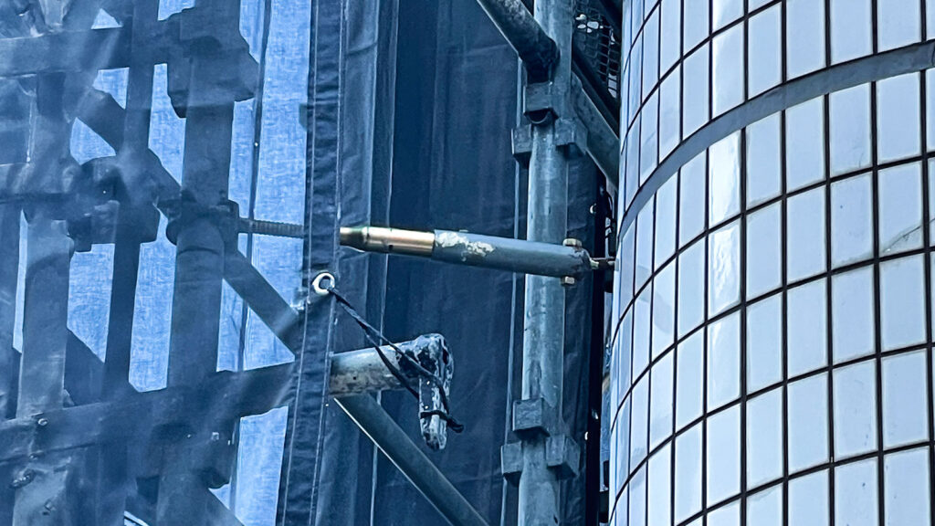
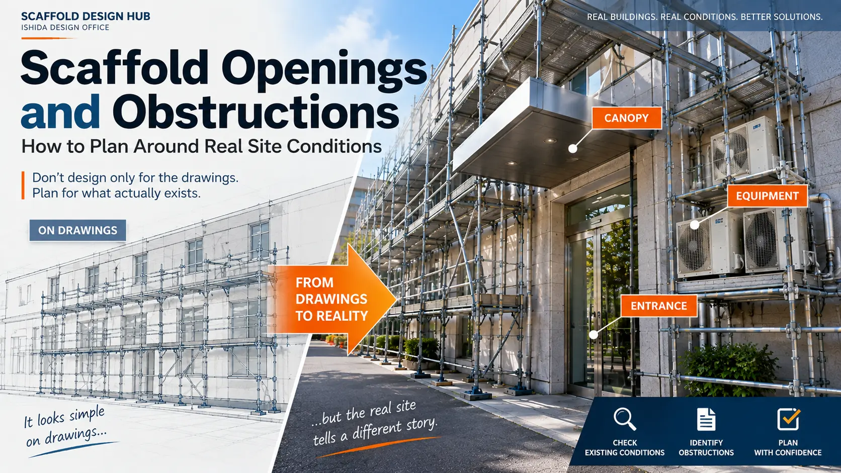
The building may have windows, cladding, glass, boards, cavities, structural framing or other features that prevent the intended connection.
In the author’s practical design experience, this difference between a theoretically convenient tie position and an actually buildable connection is a recurring issue worth checking early.
Before deciding on scaffold tie locations, I always review the building design drawings and structural arrangement. I check what supporting structural elements are available rather than assuming that the visible facade or a wall shown on a drawing is suitable for anchoring.
Glass, Boards and Façade Finishes
Glass façades are an obvious example.
The desired tie location from the scaffold layout may correspond to a façade area where a suitable structural connection cannot simply be installed.
Boarded or clad façades can create similar problems.
The visible external surface does not necessarily identify the structural element capable of receiving the load.
ALC-Type Façades and Restricted Fixing Positions
Panelised façades can also constrain tie locations.
Where panels or supporting members follow their own structural spacing, the ideal scaffold tie position may not coincide with a suitable fixing location.
The designer therefore needs information about both structures:
the scaffold geometry and the building geometry.
Masonry, Stone, Timber and Other Substrates
The existence of a wall does not automatically mean that any point on that wall is an appropriate structural fixing point.
Different substrates and existing structures have different properties, conditions and connection requirements.
Where the capacity or condition of the supporting material is uncertain, it should not simply be assumed to provide the required resistance.
Project-specific assessment and suitable fixing information may be necessary.
Structural Steel Alignment
Steel-framed buildings present another geometric issue.
The scaffold standards are positioned according to the scaffold bay layout. Structural steel is positioned according to the building structural grid.
Those two grids do not necessarily align.
The connection therefore needs to be physically feasible as well as structurally adequate.
What If the Planned Tie Position Cannot Be Used?
This is where drawing review and site reality meet.
Suppose a tie is shown at a particular location, but construction personnel discover that it cannot be installed because of glass, cladding, an opening or the position of the building structure.
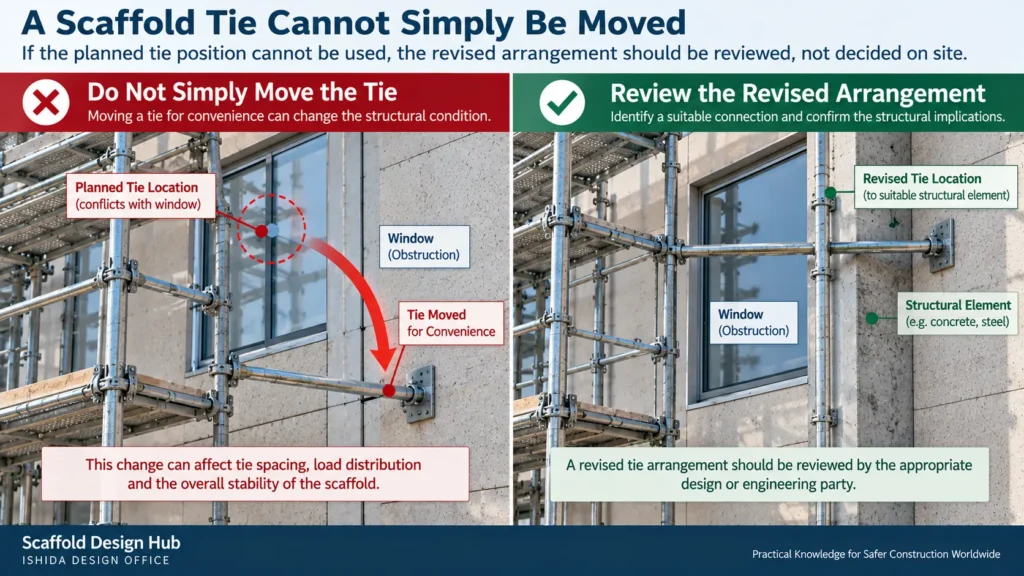
The simplest response may appear to be moving the tie.
Structurally, however, moving a tie changes the restraint arrangement.
Do Not Simply Move the Tie
A tie location should not be treated like a drawing annotation that can be shifted for convenience without considering its structural role.
Changing the location may affect:
- spacing between restraints;
- the area of scaffold associated with adjacent ties;
- local scaffold behaviour;
- upper restraint conditions;
- connection geometry;
- the load transferred to other parts of the system.
The appropriate response depends on the scaffold, the magnitude and direction of the design actions, the proposed alternative connection and the applicable design requirements.
Reassessment May Be Necessary
Where a required tie cannot be installed as designed, the revised condition should be communicated to the appropriate design or engineering party.
HSE guidance gives a related operational principle: if a tie must be removed to allow work to proceed, an equivalent tie should be provided nearby to maintain stability.
This does not mean that every relocation can be solved by simply adding another tie nearby. Rather, it demonstrates why restraint changes should be managed rather than improvised.
When a conventional tie cannot be installed as planned, I consider whether an appropriate steelwork clamp, including a catch clamp where suitable, could be used on a steel-framed building. I also examine whether a properly engineered tubular restraint or raking support arrangement (yarazu) is feasible. A specially designed welded connection may be considered only as a last resort where the existing structure, welding conditions and required approvals permit it. These are options for engineering assessment, not interchangeable or automatically approved solutions.
Tie Loads on Scaffold Drawings
A useful scaffold drawing should communicate more than a visually regular pattern.
The exact information required depends on the project, jurisdiction, scaffold system and design documentation, but the drawing and supporting design information should be consistent with each other.
What a Designer Should Communicate
Depending on the project, useful information may include:
- intended tie locations;
- relevant tie type or specification reference;
- areas where special connection details apply;
- restrictions or assumptions affecting tie installation;
- sheeting or enclosure conditions relevant to the design;
- reference to supporting calculations or design documentation where required.
HSE’s scaffold information guidance lists maximum tie spacing and tie duty among the information that may need to be provided before installation.
Drawing Versus Actual Site Conditions
One problem the author has seen in drawing work is a tie symbol shown where the tie cannot realistically be installed.
This is why constructability review matters.
Before finalising a tie layout, ask:
- What is behind the façade at this position?
- Can the fixing actually be installed?
- Is the identified supporting element suitable?
- Does the scaffold standard align with it?
- Are there openings or finishes in the way?
- Does the site condition match the information used for design?
A technically neat elevation is not enough if it cannot be built.
I make a point of checking the anchor manufacturer’s technical catalogue for the applicable allowable capacity and installation requirements. I compare the stated conditions with the actual substrate, proposed fixing and required design forces; an anchor cannot be selected solely by its size or appearance.
International Requirements Differ
There is no single universal scaffold tie-spacing rule that can be copied from one country and applied everywhere.
Requirements vary by jurisdiction, scaffold type, system, manufacturer and project.
United States — OSHA
For supported scaffolds covered by OSHA 29 CFR 1926.451(c)(1), scaffolds exceeding a specified height-to-base-width ratio must be restrained from tipping by guying, tying, bracing or equivalent means.
OSHA also specifies conditions for the positioning and repetition of those restraints and requires additional restraint where eccentric loads can cause tipping.
These provisions are U.S. regulatory requirements for the conditions they cover—not global design rules.
OSHA has also clarified in its April 8, 2005 standard interpretation that even where maximum tie intervals are specified, closer restraint may be required where necessary to satisfy scaffold capacity requirements.
United Kingdom — HSE
HSE guidance emphasises tying scaffolds into a permanent structure or otherwise stabilising them, using ties within their safe working load, following manufacturer instructions for proprietary systems and considering sheeting or netting during scaffold design.
This provides a useful practical principle beyond any individual spacing value:
Tie arrangement, tie capacity, scaffold configuration and enclosure condition need to be considered together.
Why Manufacturer and Project Requirements Still Matter
Regulatory guidance is only one part of the design information.
The scaffold system manufacturer’s instructions, project specifications, structural design information and site-specific conditions may impose additional or different requirements.
A number taken from a regulation or guidance document should therefore never be used without understanding its jurisdiction and conditions of application.
Practical Experience: Problems Worth Checking Early
1. The Ideal Tie Position Is Not Always Buildable
Corners, façade geometry and scaffold bay arrangement can prevent the preferred tie location from being used.
Identify difficult interfaces before the scaffold reaches that level wherever possible.
2. The Façade Surface May Hide the Real Supporting Structure
Glass, boards, cladding and panel systems can make a façade appear straightforward on a drawing while the actual structural connection is elsewhere.
Review the building information rather than relying only on the visible wall line.
3. Upper Scaffold Geometry Deserves Separate Attention
Do not assume that the highest part of the scaffold behaves exactly like a typical intermediate lift.
Check the relationship between the highest restraint and the scaffold above it against the applicable design requirements.
4. Sheet Changes Need Communication
If the enclosure changes after design, communicate the change.
Do not assume that the original wind-related design assumptions remain valid.
5. Tie Spacing Should Not Be Based Only on Habit
Site experience is valuable, but tie spacing must remain consistent with the applicable design basis, regulations, project requirements and manufacturer instructions.
Common Tie-Load Design Mistakes
Mistake 1 — Choosing Tie Spacing Without Adequate Design Basis
Why it matters: A familiar spacing pattern may not represent the actual wind, geometry, enclosure or building conditions.
Better approach: Confirm the relevant design conditions and applicable requirements before finalising the restraint arrangement.
Mistake 2 — Ignoring the Uppermost Tie Condition
Why it matters: The geometry above the highest effective restraint can be different from the regular scaffold below.
Better approach: Review the upper scaffold configuration separately rather than assuming a standard intermediate arrangement applies.
Mistake 3 — Showing Ties Where They Cannot Be Installed
Why it matters: A drawing symbol provides no restraint if the physical connection cannot be constructed.
Better approach: Coordinate the tie layout with actual façade and structural information.
Mistake 4 — Checking the Tie Component but Not the Building Connection
Why it matters: The complete load path includes the fixing and supporting structure.
Better approach: Identify where the force goes after it leaves the scaffold tie.
Mistake 5 — Ignoring Manufacturer Installation Requirements
Why it matters: A component may not achieve its intended performance if installed outside its specified configuration.
Better approach: Use current manufacturer documentation for the actual system and component.
Mistake 6 — Changing Sheeting Without Reviewing the Design Condition
Why it matters: The enclosure can change wind effects and therefore the demands on the restraint system.
Better approach: Treat enclosure changes as design-information changes and communicate them accordingly.
Mistake 7 — Moving or Removing Ties Informally on Site
Why it matters: Changing a restraint location changes the structural configuration.
Better approach: Escalate the revised condition for appropriate review rather than relying solely on site convenience.
Scaffold Tie Load Review Checklist
Before accepting a scaffold tie arrangement, consider the following questions:
- ☑ Has the actual scaffold system been identified?
- ☑ Are the tie components and relevant manufacturer information known?
- ☑ Are the wind and environmental design conditions defined?
- ☑ Is sheeting, netting or another enclosure included?
- ☑ Does the actual enclosure match the design assumption?
- ☑ Are scaffold height, lift levels and upper scaffold geometry known?
- ☑ Are corners, ends, openings and irregular areas reviewed separately?
- ☑ Can every critical tie shown on the drawing actually be installed?
- ☑ Is the building element receiving each tie load identifiable?
- ☑ Is the proposed fixing appropriate for the supporting substrate?
- ☑ Are façade finishes concealing or restricting access to the structural connection?
- ☑ Do scaffold standards and building structural elements align sufficiently for the proposed connection?
- ☑ Have site changes affecting tie positions been communicated?
- ☑ Are drawing information and supporting design documentation consistent?
- ☑ Are local regulations, project requirements and manufacturer instructions current and applicable?
This checklist is intentionally a review tool rather than a calculation procedure. It does not replace project-specific engineering assessment.
FAQ
What causes loads in scaffold ties?
Tie loads can arise from lateral actions acting on the scaffold, with wind being an important example. Scaffold geometry, restraint arrangement, sheeting or netting and other project-specific conditions can affect how those forces reach individual ties.
Does every scaffold tie carry the same load?
Not necessarily. Load distribution depends on the scaffold configuration, restraint layout, geometry, structural behaviour and applied actions. Equal-looking spacing does not automatically mean equal tie force.
Can a scaffold tie be moved if the planned position cannot be used?
It should not be moved purely as a drawing adjustment without considering the structural consequences. A changed tie location can alter the restraint arrangement and may require review.
Does adding debris netting affect scaffold tie loads?
It can. HSE specifically warns that sheeting or debris netting should not be added without informing those responsible for design and erection because the scaffold needs to be designed for that condition.
Is anchor capacity the same as scaffold tie capacity?
No. They are different parts of the load path. The tie component, fixing or anchor, supporting substrate and building structure all need to be appropriate for the forces they are intended to transfer.
Related Topics
- Scaffold Ties Explained: Types, Spacing & Layout — Start here if you first need to understand tie types, spacing and layout.
- Scaffold Wind Loads Explained: What Designers Need to Consider — The natural next topic for understanding one of the major actions that can generate scaffold tie demand.
- Scaffold Stability Explained: How Bracing, Ties and Bases Work Together — See how ties fit into the broader scaffold stability system.
Key Takeaways
- A scaffold tie is part of a load path; it is not simply a point shown on a drawing.
- The load path continues through the tie, fixing or anchor and into the supporting building structure.
- Tie loads can change with wind conditions, scaffold geometry, restraint layout and enclosure conditions.
- A tie shown in an ideal drawing location may not be physically installable because of façade or structural conditions.
- The top of the scaffold, corners and irregular areas deserve specific review.
- Changing sheeting or tie positions after design can change the structural condition and should be communicated.
- Tie spacing should follow the applicable design basis, regulations and manufacturer requirements rather than habit alone.
Conclusion
Understanding scaffold tie loads begins with one question:
Where does the force go?
The answer should extend beyond the scaffold frame and tie component to the fixing and the supporting building structure.
For practical design review, check not only whether the drawing contains enough ties, but whether the intended load path is structurally meaningful, physically buildable and consistent with the actual scaffold, enclosure and building conditions.
The natural next step is to understand the wind actions that create much of this lateral demand and how enclosure conditions can change them.
Official References
- OSHA — 29 CFR 1926.451, General Requirements for Scaffolds
Authority: Occupational Safety and Health Administration
Jurisdiction: United States
Supports: Supported-scaffold restraint requirements, positioning of guys, ties and braces, and eccentric-load restraint. - OSHA — Tie-in Requirements for Supported Scaffolds, April 8, 2005
Authority: Occupational Safety and Health Administration
Jurisdiction: United States
Note: Interpretation of existing OSHA requirements.
Supports: Maximum regulatory tie intervals do not remove the need for closer restraint where required to satisfy scaffold capacity requirements. - HSE — Scaffolds
Authority: Health and Safety Executive
Jurisdiction: Great Britain
Supports: Scaffold stability, tie duty, manufacturer instructions, replacement of removed ties and sheeting/netting considerations. - HSE — Structural Stability During Alteration, Demolition and Dismantling
Authority: Health and Safety Executive
Jurisdiction: Great Britain
Context: Alteration, demolition and dismantling work.
Supports: The effect of sheeting on wind action and loads applied to the building in the stated context. - Safe Work Australia — General Guide for Scaffolds and Scaffolding Work
Authority: Safe Work Australia
Jurisdiction: Australia / model WHS guidance
Version note: Current official hosting page; linked guide originally dated July 2014.
Supports: Wind and environmental loads, anchors, supporting structures, screens and containment sheeting as scaffold design considerations.
Last Verified: September 2026
Regulations, official guidance and manufacturer documentation may change. Always confirm the current requirements applicable to the project location, scaffold system and intended use.
This article is general technical information and is not a substitute for project-specific engineering, applicable law, contract documents, project specifications, manufacturer instructions or competent professional review.
About the Author
ISHIDA DESIGN OFFICE brings more than 30 years of practical experience in Japan, specializing in scaffolding design, temporary works planning, CAD drafting, quantity estimation, and construction support.
Drawing on experience from residential, commercial, and industrial projects, he shares practical insights that emphasize not only sound engineering design but also buildability, safety, and real-world jobsite application.
At Scaffold Design Hub, he combines practical experience from Japan with official guidance and technical resources from government agencies, manufacturers, and industry organizations around the world to provide reliable, practical information for construction professionals.
To learn more, visit the About page. For questions or project inquiries, please use the Contact page.