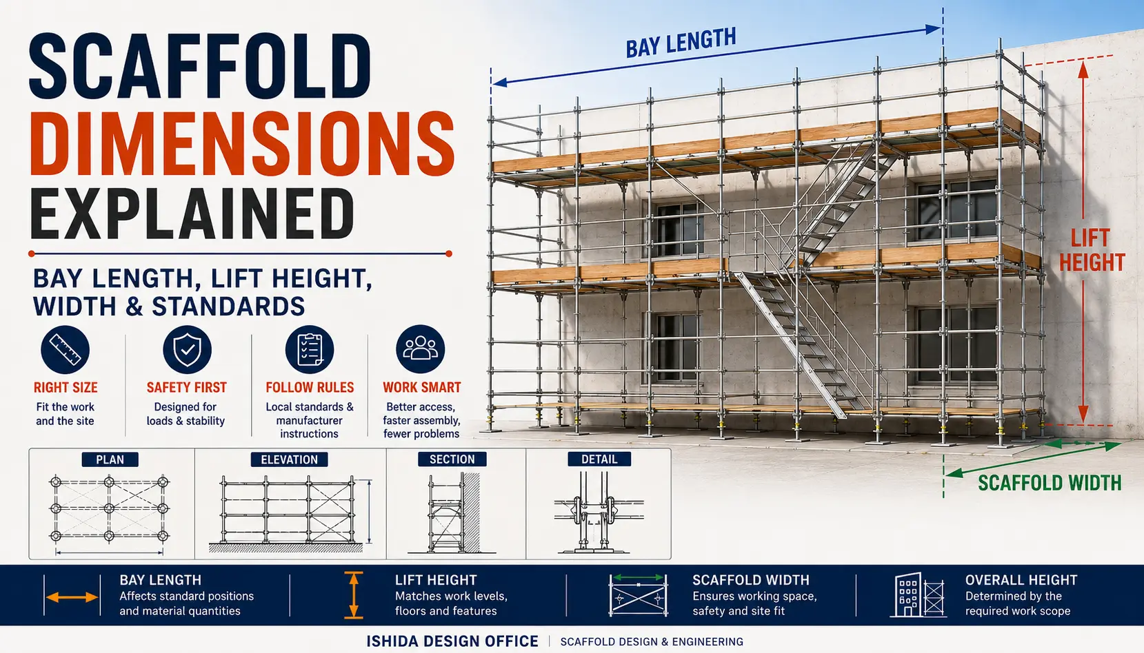
A scaffold can look perfectly regular on a drawing and still cause problems the moment erection starts.
A standard lands in front of an entrance. A platform level does not match the work area. The scaffold is too narrow for the task, or too wide for the available site space. A bay that looked economical during estimating becomes awkward when it meets a balcony, canopy or corner.
I have spent more than 30 years working with scaffold drawings, temporary works planning, quantity take-offs and practical design decisions. One lesson has stayed with me throughout that time:
Scaffold dimensions are not just numbers. They are decisions about how the scaffold must work around a real building.
If you remember only three things from this article, make them these:
- There is no single worldwide “standard scaffold dimension.”
- Bay length, lift height and scaffold width must be considered together.
- The correct dimensions depend on the scaffold system, work, loading, building geometry, local requirements and manufacturer instructions.
This article focuses on the dimensions of the assembled scaffold layout.
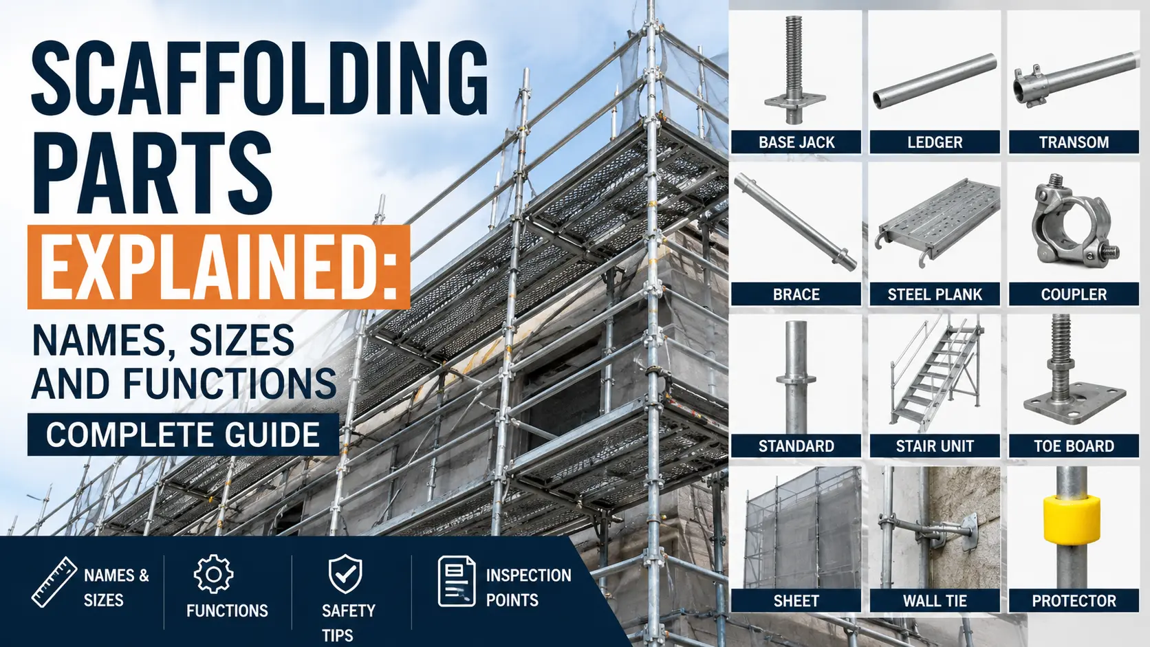
If you are looking for individual component names and component sizes, see Scaffolding Parts Explained: Names, Sizes and Functions. Keeping these subjects separate matters: the size of an individual component is not the same thing as the geometry of a complete scaffold.
Requirements vary by country, jurisdiction, and project.
Always follow local laws, project specifications, approved design information and the scaffold manufacturer’s instructions.
Why Scaffold Dimensions Matter More Than They Look
Bay length, lift height and scaffold width affect much more than how tidy a drawing looks. They influence access, working position, quantities, loading, ties, site coordination and how smoothly the scaffold can actually be erected and used.
In drawing reviews, I often find that the dimensions themselves are easy to read. The difficult part is recognising when a familiar dimension no longer works because the building or work conditions have changed.
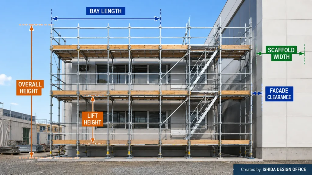
The four dimensions I check first
| Dimension | Direction | Practical question |
| Bay Length | Along the scaffold | Where will the standards actually land? |
| Lift Height | Vertical | Are the working levels in the right place? |
| Scaffold Width | Away from the facade | Is there enough room to work, and does the scaffold fit the site? |
| Overall Height | Vertical | How high must the scaffold extend for the required work? |
There is also a fifth dimension that I rarely ignore:
the distance between the scaffold platform and the building face.
That distance can affect access to the work, working comfort and fall-protection arrangements.
The problem with the word “standard”
On site, it is common to hear:
“We always use this bay.”
or:
“Our normal lift is 2 metres.”
That may be completely reasonable within a particular scaffold system or company standard.
But normal and required are not the same thing.
One proprietary scaffold can use one set of modules while another uses a different geometry. For example, PERI’s official documentation describes PERI UP Easy frame widths of 67 cm and 100 cm, while other PERI UP configurations use different modular widths.
That is a useful reminder:
Do not turn a familiar module into a universal rule.
Why dimensional mistakes become expensive
A poor dimensional decision can create:
- Extra standards and ledgers
- Unexpected transition bays
- Additional brackets
- Access conflicts
- Stair-tower relocation
- Drawing revisions
- Incorrect quantity take-offs
- Delayed erection
- Rework
- Additional engineering review
A small discrepancy on a drawing can become a much larger problem once materials and workers are already on site.
That is why I prefer to find dimensional conflicts before erection starts.
Understanding Bay Length in Real Scaffold Planning
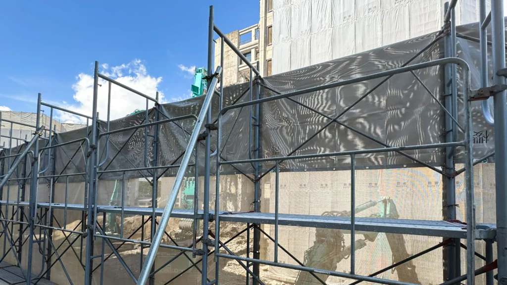
Bay length is the horizontal module between adjacent standards along the scaffold run. It appears simple on a drawing, but it is often where the first real conflict between the scaffold and the building occurs.
In my scaffold drawing work, I do not normally begin by dividing the facade into equal rectangles and assuming the layout is solved.
I look first for the places where regular bays are likely to fail.
These commonly include:
- Entrances
- Corners
- Balconies
- Canopies
- Columns
- Loading areas
- Stair towers
- Roof changes
- Service penetrations
- Narrow boundaries
- Vehicle routes
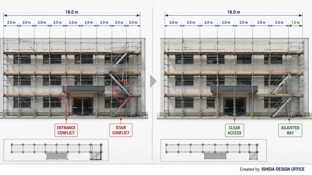
From my design work: I have had to adjust bay arrangements in my scaffold design work in Japan because the planned bays conflicted with building entrances or openings. When revising the layout, I also considered how to arrange standard scaffold components neatly and practically. The aim was to accommodate the building openings without forcing a regular bay pattern where it did not fit.
Typical bay lengths are system-dependent
Depending on the scaffold system and manufacturer, you may encounter modules around:
- 1.0 m
- 1.2 m
- 1.5 m
- 1.8 m
- 2.0 m
- 2.5 m
- 3.0 m
These are illustrative dimensions commonly encountered in scaffold systems and practice.
They are not a universal approved range.
The actual bay must be checked against:
- The exact scaffold system
- Manufacturer documentation
- Intended loading
- Standard configuration limits
- Project-specific engineering requirements
The longest bay is not automatically the cheapest bay
It is easy to think:
Longer bay = fewer standards = lower cost.
Sometimes that is true.
But not always.
Increasing bay length may affect:
- Platform span
- Ledger forces
- Standard reactions
- Bracing
- Tie arrangement
- Deflection
- Load capacity
- Deck compatibility
- Working position
During quantity take-off work, I have learned to be cautious about “optimising” bay length only by reducing the number of standards.
The cheapest-looking arrangement in a spreadsheet is not useful if it creates a problem on the building.
A simple planning calculation
For early planning only:
Approximate number of bays = scaffold run length ÷ nominal bay length
For example:
24 m ÷ 2.0 m = 12 bays
Useful?
Yes.
A finished scaffold layout?
No.
Imagine that the main entrance sits exactly where one of those standards would land.
Now the real choices begin:
- Shift the bay sequence
- Introduce a shorter transition bay
- Change surrounding bay modules
- Develop an appropriate bridging arrangement
- Reconsider the stair or loading-bay position
The important decision is no longer arithmetic.
It is coordination.
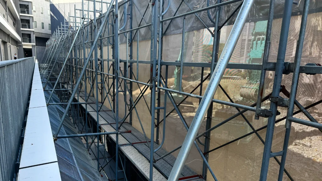
What I check before accepting a bay layout
I ask:
- Does it fit the building?
- Does it fit the scaffold system?
- Does it suit the intended loading?
- Are entrances kept usable?
- Do balconies or canopies interfere?
- Is there enough room for access?
- Can the proposed tie arrangement work?
- Are transition bays clearly identified?
- Has the estimator included the non-standard areas?
If an important question has no clear answer, I do not regard the bay arrangement as complete.
Lift Height Is About the Work, Not Only the Scaffold
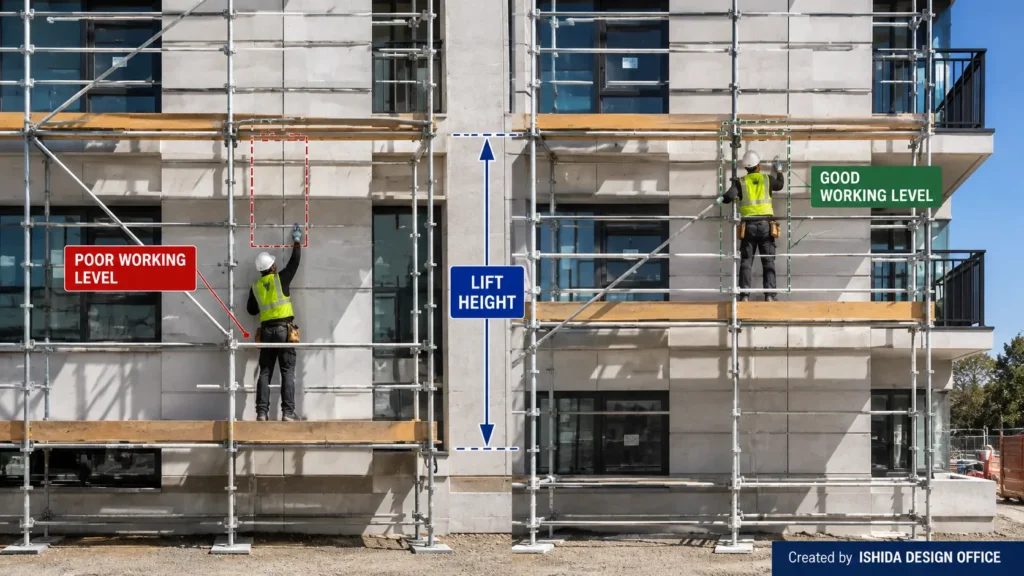
Lift height is the vertical spacing between scaffold levels or principal horizontal levels. In practical planning, I think about it in relation to the building and the worker before I think about how neatly the module repeats.
Common arrangements may use lift heights around:
- 1.5 m
- 1.8 m
- 2.0 m
Again, these are familiar examples rather than one worldwide standard.
Why approximately 2 metres appears frequently
Many scaffold systems and common configurations work well with regular vertical modules around this range.
That can make:
- Erection repetitive
- Material quantities predictable
- Drawing production easier
- Access planning simpler
But a perfectly regular lift pattern can still provide a poor working position.
For renovation drawings, I routinely compare working-platform levels with:
- Windows
- Floor slabs
- Balcony edges
- Cladding joints
- Roof edges
- Painting areas
- Mechanical equipment
- Waterproofing details
The practical question is:
Where does the worker actually need to stand?
A neat scaffold can still be awkward to use
Suppose a facade repair zone sits between two convenient scaffold levels.
If the platform is too low or too high, the worker may end up reaching awkwardly or looking for an improvised solution.
A good scaffold layout tries to reduce the need for improvisation.
That does not mean changing every lift whenever a facade detail appears.
It means checking whether the proposed platform levels support the actual work.
From my design work: In my scaffold planning work in Japan, I have adjusted working platform levels to match the positions where exterior wall work needed to be carried out. This experience is one reason I check the proposed platform heights against the actual work locations, rather than relying only on a regular vertical layout.
Preliminary lift count
For rough planning:
Approximate number of lifts = required scaffold height ÷ nominal lift height
Example:
20 m ÷ 2.0 m ≈ 10 lifts
But this number alone does not tell you:
- Which lifts are boarded
- Where access landings occur
- How the top lift is arranged
- Where ties occur
- Whether the working levels align with the building
- Whether the configuration is permitted by the system
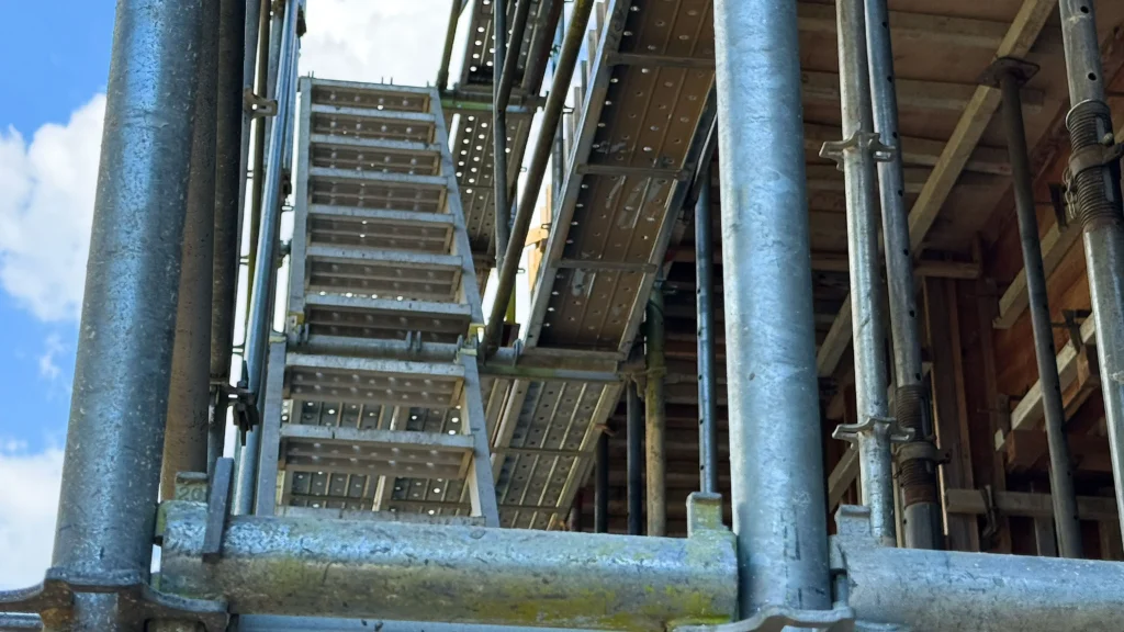
That is why I never treat lift count alone as scaffold design.
Scaffold Width: Platform Width Is Not the Whole Story
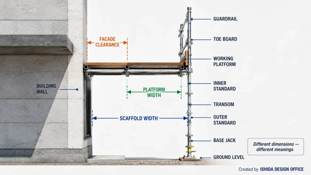
Scaffold width affects working space, access, material handling and the amount of space the scaffold occupies around the structure. A common mistake is to treat “platform width” and “scaffold width” as though they always describe exactly the same dimension.
They may not.
Depending on the system, you may be dealing with:
- Distance between inner and outer standards
- Nominal system width
- Usable platform width
- Additional bracket width
- Clearance to the facade
- Overall external envelope
When I check a section drawing, I want these relationships to be obvious.
Wider is not automatically better
A wider scaffold can provide:
- More room for workers
- Better material handling
- Easier movement
But it can also create:
- Boundary conflicts
- Reduced pedestrian space
- Reduced vehicle clearance
- More components
- Different transom requirements
- Additional loading
- Problems on narrow sites
The scaffold has to fit between the building and everything around it.
That may include a road, neighbouring property, fence, temporary route or occupied entrance.
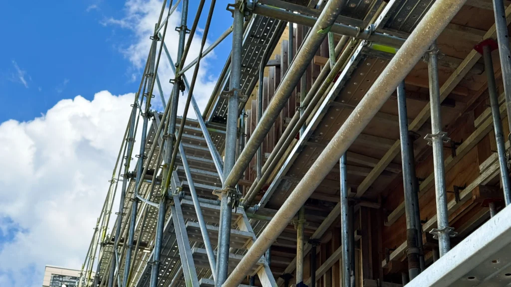
From my design work: In one of my scaffold planning projects in Japan, the working width in the initial arrangement was insufficient for workers to carry out their tasks safely. The planned working width therefore needed to be increased. This reinforced the importance of checking the space workers actually need for their tasks, rather than assuming the initial width is adequate simply because it fits on the drawing.
OSHA shows why terminology matters
Under OSHA 29 CFR 1926.451(b)(2), scaffold platforms and walkways are generally required to be at least 18 inches (46 cm) wide, subject to stated exceptions. OSHA also generally limits the front edge of platforms to 14 inches (36 cm) from the face of the work unless the specified fall-protection measures or exceptions apply.
These are platform-related requirements.
They do not mean:
“The standard scaffold width in the United States is 46 cm.”
That would be an incorrect interpretation.
HSE uses a different framework
HSE advises checking that scaffold platforms are fully boarded and wide enough for the work and access, usually at least 600 mm wide in the context of its construction scaffold guidance.
Again, this is not a universal global scaffold-width rule.
The practical lesson is:
Know exactly what a number measures before comparing dimensions from different countries.
Typical Scaffold Dimensions — Useful Ranges, Not Universal Standards
Typical dimensions are useful when reading drawings, estimating and understanding a scaffold concept. They become dangerous only when a generic table is treated as permission to use those dimensions on every scaffold.
Here is the distinction I recommend keeping in mind:
| Item | Illustrative range / example | What really controls it |
| Bay length | Around 1.0–3.0 m in many systems/practices | System, manufacturer, load and configuration |
| Lift height | Around 1.5–2.0 m is commonly encountered | System, working level and design |
| Platform width | Varies significantly | Task, system and local requirements |
| Scaffold width | System/project-specific | Manufacturer geometry and working requirements |
| Overall height | Project-specific | Building, stability and design |
| Facade clearance | Project-specific | Work type, access and fall protection |
This table is intentionally broad.
I would rather show an approximate range with a clear warning than give a precise number that someone later copies onto the wrong system.
A useful way to read any “standard dimension” table
Whenever you see a scaffold dimension online, ask:
- Which country?
- Which scaffold system?
- Which manufacturer?
- Which load class or intended duty?
- Is it a legal minimum, a system module or simply common practice?
- Does it apply to my project?
Those six questions prevent many misunderstandings.
How Bay Length, Lift Height and Width Work Together
Bay length, lift height and width are not three independent numbers. Together they create the basic three-dimensional scaffold grid, and changing one can affect several other parts of the scaffold.
I find it useful to think of the basic geometry as:
Bay Length × Scaffold Width × Lift Height
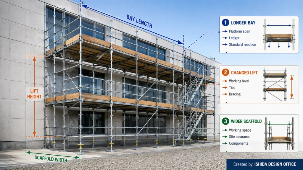
If you increase the bay length
You may change:
- Platform span
- Ledger forces
- Standard reactions
- Material quantities
- Bracing
- System capacity
If you change lift height
You may change:
- Working levels
- Bracing geometry
- Tie positions
- Access
- Number of lifts
- Relationship with the facade
If you increase scaffold width
You may change:
- Working space
- Platform arrangement
- Component quantities
- Transom configuration
- Site clearance
- Structural behaviour
This is why I do not like reviewing a scaffold dimension one cell at a time.
I prefer to look at the complete arrangement.
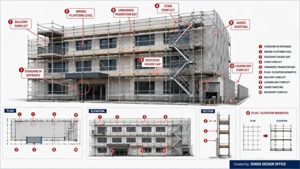
A bay that appears reasonable in plan may become problematic in elevation.
A width that appears reasonable in section may make the scaffold impossible to place within the site boundary.
And a lift that looks perfectly repetitive may be at the wrong height for the work.
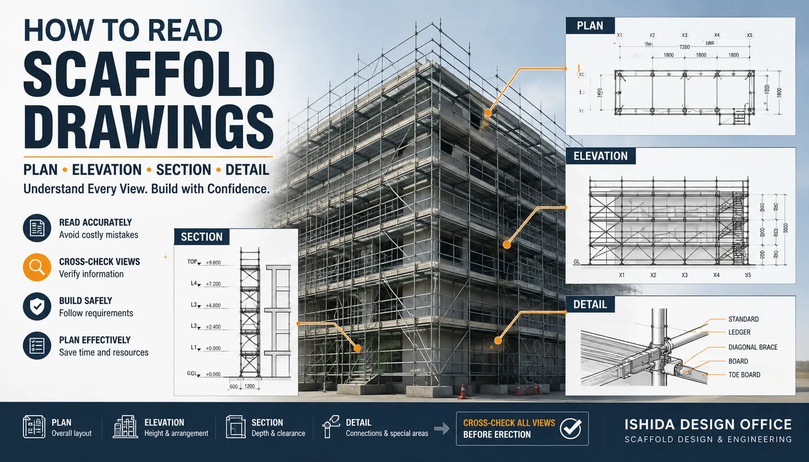
Plan, elevation and section need to tell the same story.
Japanese Practice Note
One thing that has strongly influenced my scaffold drawing work in Japan is the need to make the scaffold fit the site before assuming that the site will somehow accommodate the scaffold.
Many renovation projects are surrounded by tight boundaries, occupied buildings, pedestrian routes, entrances, balconies, external equipment and neighbouring properties. In that environment, a few hundred millimetres can matter. I have therefore developed the habit of checking difficult interfaces early: entrances, corners, canopy edges, stair locations, loading routes and narrow passages.
The same thinking applies to quantity take-offs. A drawing may show mostly repetitive bays, but short transition bays, returns and non-standard areas can change the material list more than they first appear to. I prefer to identify these areas clearly on the drawing rather than leave the erection team to resolve them informally on site.
Another practical habit is to pay attention to small inconsistencies between the plan, elevation and section. A dimension that looks reasonable in one view can reveal a problem when checked in another.
None of these habits is uniquely Japanese, and they can be useful on projects anywhere.
Requirements vary by country, jurisdiction, and project. Always confirm local regulations, project requirements and the scaffold manufacturer’s latest instructions.
International Perspective: What the Rules Actually Tell Us
International rules point toward a common principle: a scaffold must be suitable for its intended use, safely configured and loaded, and consistent with the applicable design or manufacturer requirements.
They do not provide one global table saying that every scaffold must use the same bay, lift and width.
United States — OSHA
OSHA 29 CFR 1926.451 requires, with the stated exceptions, each scaffold and scaffold component to support its own weight and at least four times the maximum intended load applied or transmitted to it.
The same section states that scaffolds must be designed by a qualified person and constructed and loaded in accordance with that design.
For platform geometry, OSHA includes requirements such as:
- Platforms and walkways generally at least 18 in (46 cm) wide
- Restrictions on gaps between platform units
- A general maximum front-edge distance of 14 in (36 cm) from the face of work, unless the required protective measures or stated exceptions apply
Notice what OSHA does not say.
It does not tell every scaffold to use:
- a 2.0 m bay
- a 2.0 m lift
- a 0.9 m scaffold width
The arrangement still has to suit the scaffold and its design.
United Kingdom — HSE
HSE takes a particularly useful approach to scaffold dimensional information.
Before installation, the information supplied for scaffold planning can include:
- Height and length
- Critical dimensions
- Number of boarded lifts
- Maximum working loads
- Access requirements
- Sheeting or netting
- Ground conditions
- Building information
HSE then identifies information the scaffold contractor or designer should provide, including:
- Scaffold type
- Maximum bay lengths
- Maximum lift heights
- Platform arrangement
- Load class
- Maximum leg loads
- Horizontal and vertical tie spacing
- Tie duty
This is exactly why I prefer thinking about a coordinated scaffold configuration instead of searching for one “standard dimension.”
HSE also states that scaffolds should normally be treated as general purpose with a maximum load of 2 kN/m² (200 kg/m²) unless the scaffold provider advises otherwise, and it warns against adding sheeting or debris netting without involving those responsible for the scaffold design and erection.
Australia — Safe Work Australia
Safe Work Australia emphasises risk management for hazards such as falls, collapse, falling objects and work near power lines.
Under the model WHS framework, scaffolding work involving a platform from which a person or object could fall more than 4 metres requires the appropriate high-risk work licence.
Scaffolding work involving a risk of falling more than 2 metres is high-risk construction work requiring a Safe Work Method Statement.
Safe Work Australia also makes clear that the Commonwealth, states and territories regulate and enforce WHS laws, so the relevant state or territory regulator must be checked.
Japan
Japan provides another useful example of why international numbers should not be mixed without context.
Under Article 563 of Japan’s Industrial Safety and Health Regulations, for scaffold working floors within the provision’s scope at workplaces 2 m or more above ground, the current requirements include:
- Working-floor width of at least 40 cm
- Gaps between floor materials of no more than 3 cm
- Gap between floor material and standards of less than 12 cm
Article 562 also requires the employer to establish and observe the maximum loading for the working floor according to the scaffold’s structure and materials.
These are Japanese requirements within a specific regulatory framework.
They should not be copied and treated as US, UK or Australian design rules.
A practical international hierarchy
When I work through an unfamiliar requirement, I use this order:
Local law → project requirements → recognised guidance → manufacturer instructions → project-specific design
Do not reverse that process by starting with a number found on an old drawing.
Manufacturer Dimensions: Why One “Standard Size” Does Not Exist
System scaffolds are modular products. Their geometry is therefore strongly influenced by the manufacturer.
That is one of the strongest reasons to be cautious with generic “standard scaffold size” tables.
For example, PERI’s official PERI UP Easy documentation describes Easy frame system widths of 67 cm and 100 cm, while PERI UP Flex uses other system widths and modular deck arrangements.
The point is not that these dimensions are better than another manufacturer’s dimensions.
The point is:
The system defines the available geometry.
The UK NASC makes the same broader distinction in a different way: TG20 covers tube-and-fitting scaffolding, while TG30 addresses system scaffolding and works with manufacturer/system-specific configurations within its scope.
Before deciding that a bay, width or lift is “standard,” identify the actual scaffold system first.
Common Scaffold Dimension Mistakes I See in Drawing Work
The most frustrating dimensional mistakes are often simple ones. They usually happen because someone uses a familiar arrangement without asking whether the building, work or scaffold system has changed.
1. Making every bay equal
Regular bays are efficient.
Buildings are not always regular.
Do not sacrifice buildability simply to make the drawing look repetitive.
2. Treating a familiar dimension as a legal requirement
A company may regularly use a 2.0 m bay or lift.
That does not mean the law requires every scaffold to use it.
Always separate:
company practice / manufacturer module / recognised configuration / regulatory requirement
3. Confusing platform width with scaffold width
These are not automatically the same measurement.
Show clearly what each dimension refers to.
4. Ignoring facade clearance
A scaffold may have an acceptable nominal width but still be too far from the working face.
Check the actual section.
5. Selecting lifts without checking the work
A regular vertical grid may place the platform at an awkward level for windows, cladding or roof details.
Check where the worker needs to stand.
6. Optimising only for quantities
Removing standards may look cheaper during estimating.
But a longer span or changed configuration may affect capacity and require other changes.
7. Forgetting transition bays
One short bay does not mean only one short ledger.
It can affect:
- Decks
- Transoms
- Guardrails
- Toe boards
- Bracing
- Ties
- Corner quantities
This is where estimating errors often begin.
8. Allowing plan, elevation and section to disagree
I always regard this as a warning sign.
If the plan shows one arrangement and the elevation implies another, someone on site will eventually have to decide which one is correct.
9. Ignoring sheeting or netting
A scaffold initially planned as open can behave very differently once sheeting is added.
HSE specifically warns that those responsible for design and erection should be informed before sheeting or debris netting is attached.
10. Copying the previous project
Old drawings can be useful references.
They are not proof that the same configuration is suitable for a new project.
Different buildings, ground conditions, loading, exposure or scaffold systems can change the answer.
Practical Scaffold Dimensions Checklist
A checklist does not replace engineering judgment.
It simply helps prevent small questions from being forgotten when a project becomes busy.
Before choosing the bay layout
- Confirm the exact scaffold system
- Obtain current manufacturer instructions
- Confirm available bay modules
- Confirm building dimensions
- Locate entrances
- Locate corners and returns
- Locate balconies and canopies
- Confirm stair and access positions
- Identify loading bays and hoists
- Mark short or transition bays
Before choosing lift heights
- Confirm required scaffold height
- Confirm building floor levels
- Identify actual work zones
- Check windows and openings
- Check balconies
- Check roof and parapet levels
- Check access landing levels
- Confirm system/configuration limits
- Coordinate ties and bracing
Before accepting scaffold width
- Confirm nominal system width
- Confirm usable platform width
- Confirm task requirements
- Check facade clearance
- Check site boundary
- Check pedestrian clearance
- Check vehicle clearance
- Check brackets and inside platforms
- Confirm loading requirements
Structural and loading review
- Intended duty confirmed
- Boarded lifts identified
- Material loading understood
- Loading bays identified
- Sheeting/netting confirmed
- Wind exposure considered where required
- Tie arrangement coordinated
- Bracing coordinated
- Ground/support conditions reviewed
- Non-standard configurations referred for appropriate design
Drawing coordination
- Bay lengths shown
- Lift heights shown
- Scaffold width shown
- Overall height shown
- Facade clearance understandable
- Plan matches elevation
- Elevation matches section
- Special details referenced
- Revision status clear
- Quantity take-off reflects non-standard areas
If an important dimension is unknown, mark it as unknown.
Do not hide uncertainty behind a clean drawing.
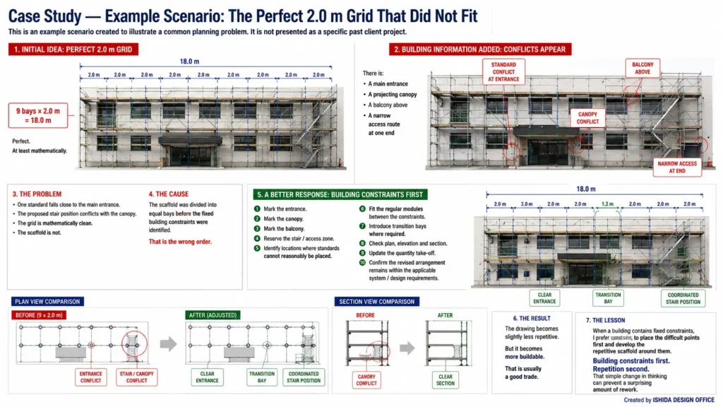
Case Study — Example Scenario: The Perfect 2.0 m Grid That Did Not Fit
This is an example scenario created to illustrate a common planning problem. It is not presented as a specific past client project.
Consider an 18 m renovation facade.
The first layout looks obvious:
9 bays × 2.0 m = 18.0 m
Perfect.
At least mathematically.
Then the building information is added.
There is:
- A main entrance
- A projecting canopy
- A balcony above
- A narrow access route at one end
The problem
One standard falls close to the main entrance.
The proposed stair position conflicts with the canopy.
The grid is mathematically clean.
The scaffold is not.
The cause
The scaffold was divided into equal bays before the fixed building constraints were identified.
That is the wrong order.
A better response
- Mark the entrance.
- Mark the canopy.
- Mark the balcony.
- Reserve the stair/access zone.
- Identify locations where standards cannot reasonably be placed.
- Fit the regular modules between the constraints.
- Introduce transition bays where required.
- Check plan, elevation and section.
- Update the quantity take-off.
- Confirm the revised arrangement remains within the applicable system/design requirements.
The result
The drawing becomes slightly less repetitive.
But it becomes more buildable.
That is usually a good trade.
The lesson
When a building contains fixed constraints, I prefer to place the difficult points first and develop the repetitive scaffold around them.
Building constraints first. Repetition second.
That simple change in thinking can prevent a surprising amount of rework.
FAQ
What is the standard scaffold bay length?
There is no single worldwide standard bay length.
Many scaffold systems use modules somewhere around the 1.0–3.0 m range, but the permitted bay length depends on the exact scaffold system, manufacturer documentation, load, configuration and project-specific requirements.
What is a typical scaffold lift height?
Lift heights around 1.5–2.0 m are commonly encountered, and approximately 2.0 m is familiar in many scaffold arrangements.
However, a common dimension is not automatically an approved dimension for your scaffold.
Check the actual system and design requirements.
How wide should a scaffold be?
There is no single universal scaffold width.
The correct width depends on:
- Scaffold system
- Working task
- Platform arrangement
- Available site space
- Local requirements
- Manufacturer instructions
Also remember that platform width and overall scaffold width are not necessarily the same dimension.
Does increasing bay length reduce scaffold cost?
It can reduce the number of certain components.
But longer bays may also change platform spans, loading, capacity and other requirements.
So a longer bay is not automatically the cheapest overall solution.
Can I change the bay length on site?
Do not treat a different bay as a harmless adjustment simply because it fits the building better.
The revised configuration should be checked against the approved design or recognised configuration, manufacturer requirements and any effects on loading, ties, bracing and access.
Are scaffold dimensions the same in every country?
No.
Regulations, terminology, scaffold systems and standard practices differ between jurisdictions.
Requirements vary by country, jurisdiction, and project.
Always check the applicable local rules and current manufacturer documentation.
Related Topics
Scaffold dimensions become much easier to apply when they are connected to drawings, components and real design decisions.

Key Takeaways
After more than 30 years of working with scaffold drawings, quantities and temporary works planning, these are the five points I would keep:
- There is no single universal scaffold dimension. Bay, lift and width depend on the system, task, loading, building and jurisdiction.
- Bay length is a planning decision, not just a division calculation. Deal with building constraints before forcing a repetitive grid.
- Lift height should support the work. Think about where people actually need to stand.
- Platform width and scaffold width are not automatically the same dimension. Always be precise about what is being measured.
- Dimensions interact. Changing one can affect quantities, access, loading, ties, bracing and structural requirements.
And there is one principle worth repeating:
The final decision should be based on local regulations, project requirements, approved design information and manufacturer instructions.
Conclusion
Good scaffold dimensioning is rarely about finding a magic number.
It is about understanding the building, the work, the scaffold system and the people who must erect and use it.
When I review a scaffold drawing, I do not want dimensions simply because a technical drawing is expected to contain dimensions.
I want each important dimension to answer a practical question:
Where does this standard land?
Can the worker reach the work comfortably?
Does the scaffold fit the available space?
Does the system allow this arrangement?
Do the plan, elevation and section agree?
If those questions are answered before erection, the drawing has already done valuable work.
I hope this article helps you avoid one unnecessary site correction, one quantity error or one awkward scaffold arrangement on your next project.
Keep looking carefully at the small details.
The small problem you catch on a drawing today may be the large problem you never have to solve on site tomorrow.
References
Official Government and Regulatory Sources
Occupational Safety and Health Administration (OSHA) — 29 CFR 1926.451, General Requirements
Official US scaffold regulation covering capacity, qualified-person design, platform construction and related dimensional requirements.
OSHA 29 CFR 1926.451
OSHA — Scaffolding eTool
Official explanatory material for OSHA scaffold requirements.
OSHA Scaffolding eTool
Health and Safety Executive (HSE) — Scaffolds
Official UK guidance covering scaffold planning information, bay and lift limits, loading, platforms, ties and bespoke design.
HSE Scaffolds Guidance
Safe Work Australia — Scaffolding
Official Australian national guidance covering scaffold hazards, licensing and SWMS requirements.
Safe Work Australia Scaffolding
Safe Work Australia — General Guide for Scaffolds and Scaffolding Work
Official guidance on scaffold risk management and safe work.
Safe Work Australia Scaffold Guide
Ministry of Health, Labour and Welfare, Japan — Industrial Safety and Health Regulations
Official Japanese regulations including Articles 562 and 563 concerning scaffold loads and working floors.
MHLW Industrial Safety and Health Regulations
Manufacturer Source
PERI — PERI UP Easy Technical Documentation
Official manufacturer documentation showing modular system geometry and scaffold widths.
PERI UP Easy Technical Documentation
Industry Guidance
National Access & Scaffolding Confederation (NASC) — TG20 / TG30
UK industry guidance covering recognised configurations for tube-and-fitting and system scaffolding.
NASC TG20 and TG30 Information
Reference Verification
Last Verified: August 2026
All external references and official guidance listed above were checked at the time of writing.
Regulations, manufacturer manuals and industry guidance can change. Readers should confirm the latest requirements through the official sources before applying technical information to a live project.
Where state, territory or local requirements apply, consult the relevant regulator.
Safety Disclaimer
This article is intended for general educational purposes.
It is not a substitute for project-specific scaffold design, engineering calculations, competent-person assessment, approved method statements, manufacturer documentation or applicable legal requirements.
Requirements vary by country, jurisdiction, and project.
Always follow local laws, project specifications, approved design information and the scaffold manufacturer’s instructions.
Where the correct requirement is uncertain, consult the official guidance and an appropriately competent or qualified person.
About the Author
ISHIDA DESIGN OFFICE brings more than 30 years of practical experience in Japan, specializing in scaffolding design, temporary works planning, CAD drafting, quantity estimation, and construction support.
Drawing on experience from residential, commercial, and industrial projects, he shares practical insights that emphasize not only sound engineering design but also buildability, safety, and real-world jobsite application.
At Scaffold Design Hub, he combines practical experience from Japan with official guidance and technical resources from government agencies, manufacturers, and industry organizations around the world to provide reliable, practical information for construction professionals.
To learn more, visit the About page. For questions or project inquiries, please use the Contact page.