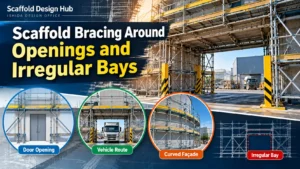
A large opening changes more than the geometry of a scaffold.
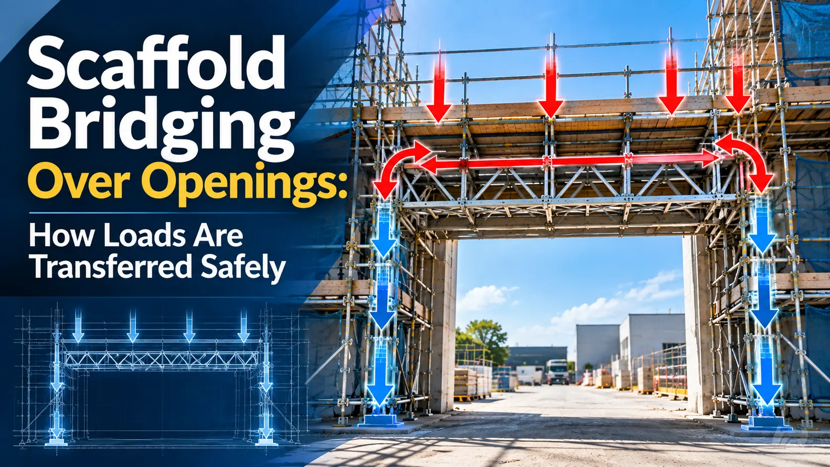
If a standard cannot continue vertically to the ground or supporting structure, the load that would normally travel through that standard does not disappear. It has to be transferred through another structural path to suitable supports.
That is why I do not look only at the width of the opening. I also want to know what is above it, how much scaffold the opening is supporting, where the loads can go, and whether the proposed arrangement can actually be built.
This article explains the design thinking behind scaffold bridging over openings without providing project-specific calculations or proprietary design methods.
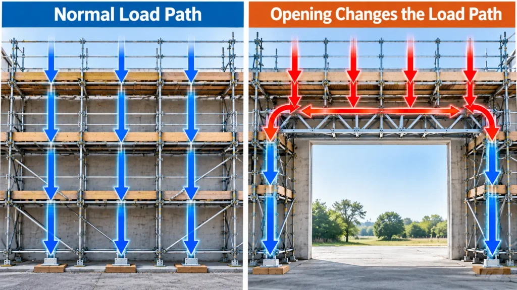
An Opening Changes the Load Path
On a conventional supported scaffold, vertical loads generally travel downward through the scaffold structure toward the supporting surface.
An opening interrupts that straightforward arrangement.
A doorway may require only a relatively limited local consideration. A wide entrance, loading access, vehicle route or other large opening can affect several standards and a much larger portion of the scaffold above.
The design question is therefore not simply:
Can a component physically span this opening?
A better question is:
What is being supported above the opening, where will those loads go, and can every part of that load path support them?
That distinction matters.
A bridging member may be adequate in isolation while the standards supporting its ends, the connections, the bracing arrangement or the supporting surface become the more important design condition.
Start by Looking Above the Opening
One of the first things I check is what exists above the opening.
The opening dimensions matter, but they are only part of the design condition.
Opening Geometry
The basic geometry includes:
- opening width;
- opening height;
- scaffold geometry around the opening;
- available locations for support;
- required clearance;
- whether pedestrians, vehicles or materials must pass through the opening.
The opening must also be considered in relation to the actual scaffold bay arrangement.
A dimension that looks straightforward on an architectural drawing may become difficult once the scaffold modules and components are laid out.
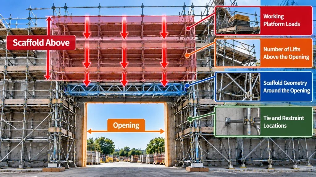
Loads Above the Opening
I also want to understand the scaffold above the opening.
Questions include:
- How high does the scaffold continue above it?
- How many lifts are being supported?
- What working-platform loads need to be considered?
- Are materials or equipment expected on the platforms?
- Are several working levels expected to be used?
- Are there locally different loading conditions?
The important point is simple:
The size of the opening alone does not tell you the structural significance of the opening.
A similar opening can represent very different design conditions depending on what the scaffold above it is required to support.
This is consistent with a broader principle I use when considering scaffold loads: the load condition should reflect the intended use of the scaffold rather than being reduced to a single assumed platform-load value.
Support and Site Conditions
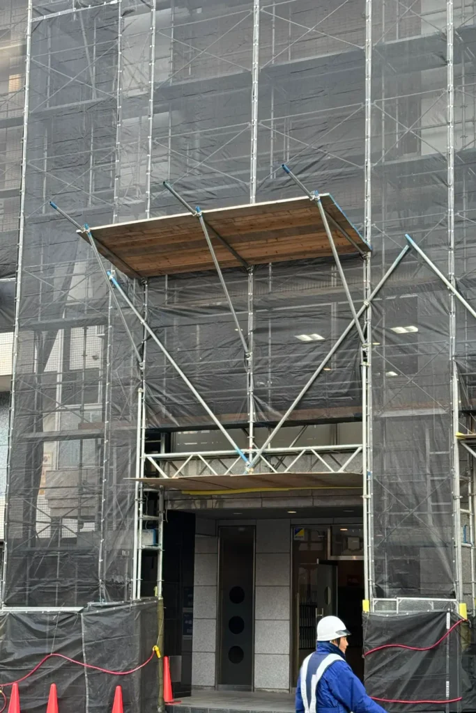
The next question is where the transferred load can actually be supported.
That means considering conditions such as:
- possible support locations;
- supporting standards;
- the structure or ground below those standards;
- wall-tie locations;
- bracing constraints;
- entrances and access routes;
- vehicle movements;
- interference with the building or existing equipment.
This is where structural planning and site planning meet.
How Does the Load Cross the Opening?
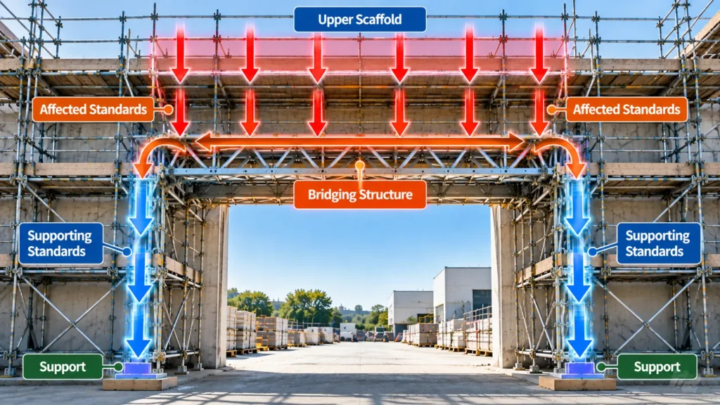
The basic concept is straightforward: the load still needs a continuous path to adequate support.
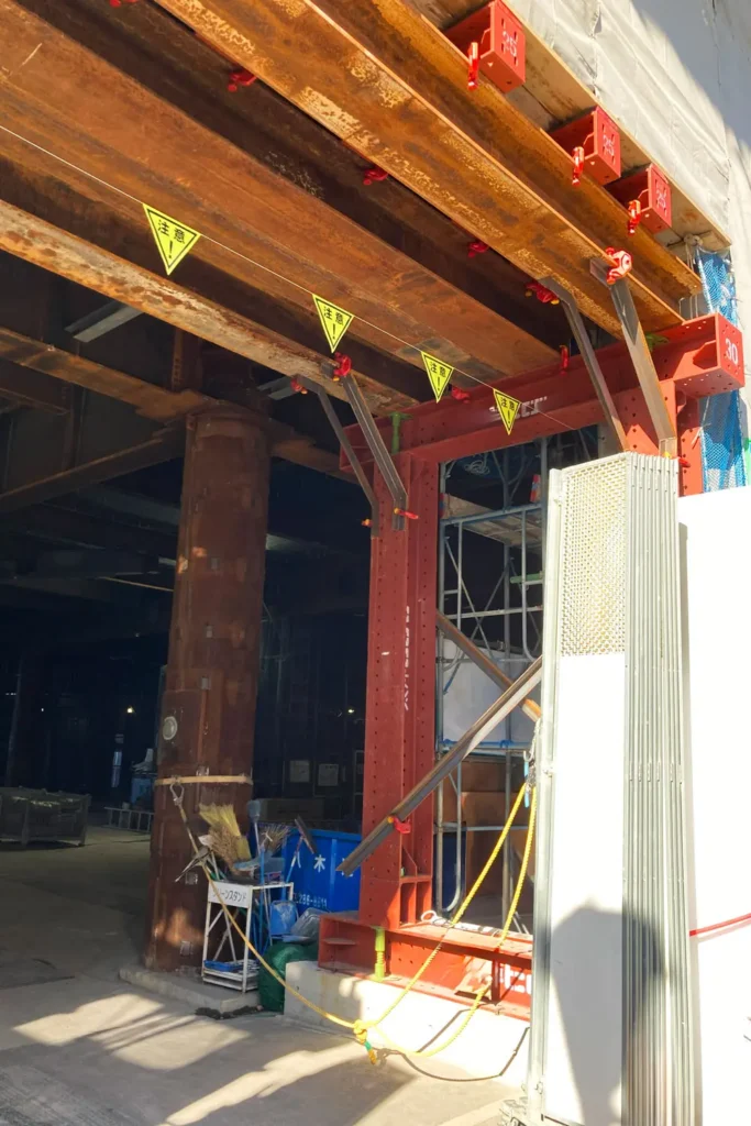
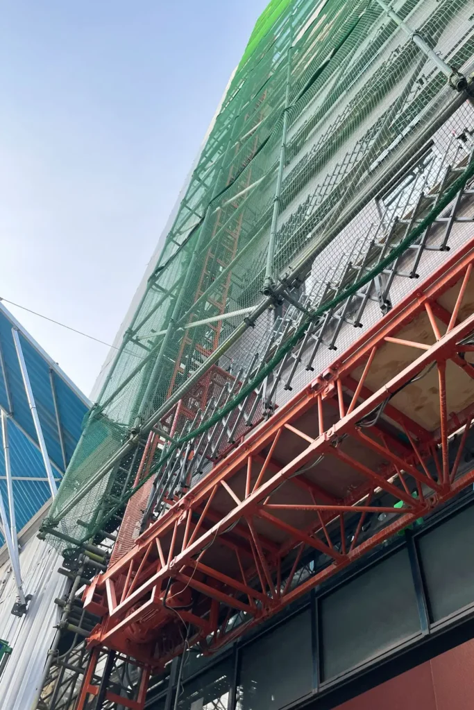
Where a normal standard cannot continue through the opening, the loads associated with the scaffold above have to be transferred through the bridging arrangement to supporting points outside or around the opening.
Conceptually, the path may be represented as:
Upper scaffold → affected standards → bridging structure → supporting standards → bases/supporting structure
The exact arrangement depends on the scaffold system, manufacturer information, geometry, loading, project conditions and applicable requirements.
This article therefore does not provide a generic bridge capacity or a universal component arrangement.
The Load Still Has to Reach a Support
It is easy to concentrate attention on the component crossing the opening.
But that is only the middle of the load path.
Once the load reaches the ends of the bridging arrangement, those reactions have to be carried by the supporting scaffold and ultimately by an adequate foundation or supporting structure.
This means the designer should not stop the review at the bridge itself.
The Bridge Member Is Only Part of the Check
Depending on the system and project, the structural review may need to consider:
- loads transferred from the scaffold above;
- the capacity of the bridging component;
- reactions delivered to the supporting standards;
- the capacity and stability of those standards;
- connections;
- bracing and overall stability;
- buckling considerations;
- bases and supporting conditions;
- ties or other restraint arrangements where relevant.
These items are interrelated.
For example, strengthening the bridging portion does not automatically prove that the supporting standards or the structure below them can accept the resulting reactions.
This is one reason I prefer to think about the entire load path rather than treating the bridge as an isolated component.
A Wider Opening Is Not Automatically an Acceptable Opening
A useful example comes from my own design experience.
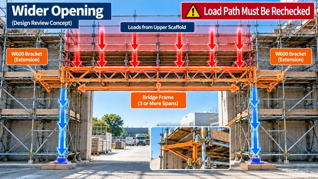
I was considering an arrangement involving a bridge frame extending across three or more scaffold spans. One idea was to place W600 brackets at both sides of the bridge arrangement to increase the usable opening width.
I did not accept that arrangement because of the resulting safety and structural concerns.
The important lesson is not the particular bracket dimension. It is that being able to draw a wider configuration does not mean that the resulting load path is acceptable.
The load above the bridge was significant enough that bracing, reinforcement of the supporting standards and buckling had to be considered as part of the structural review.
The exact calculation and reinforcement method is project-specific and is intentionally not reproduced here.
The practical lesson is broader:
Do not enlarge an opening by adding components and assume that the original structural behaviour remains unchanged.
Changes in geometry can change the way loads are transferred and the demands placed on the surrounding scaffold.
When the Drawing Works but the Scaffold Does Not
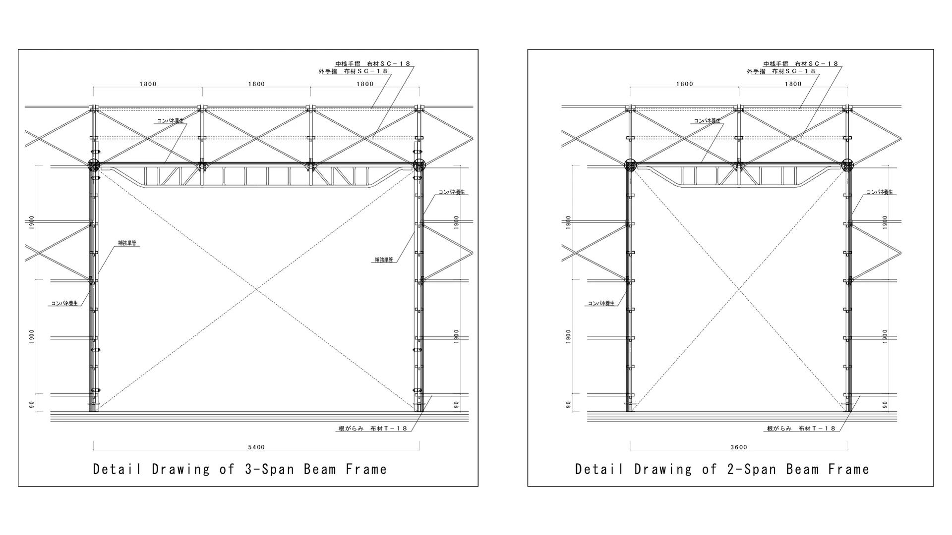
Another problem I have encountered is a bridge arrangement that appeared possible on the drawing but could not actually be fitted into the real scaffold bay layout.
This is an important distinction.
A structural concept can make sense while the physical arrangement still fails because the available scaffold components, bay positions, building geometry or adjacent elements do not allow it to be assembled as drawn.
That is why constructability should be reviewed before the drawing is treated as complete.
For an opening, I would check the plan, elevation and, where necessary, a section or detail together. Looking at only one view can hide conflicts.
The practical question is not just:
Can I draw the bridge here?
It is:
Can this arrangement actually be assembled here using the intended scaffold system while maintaining the required structural arrangement?
This is especially important around entrances, projections, changes in building geometry and other locations where the normal scaffold module is interrupted.
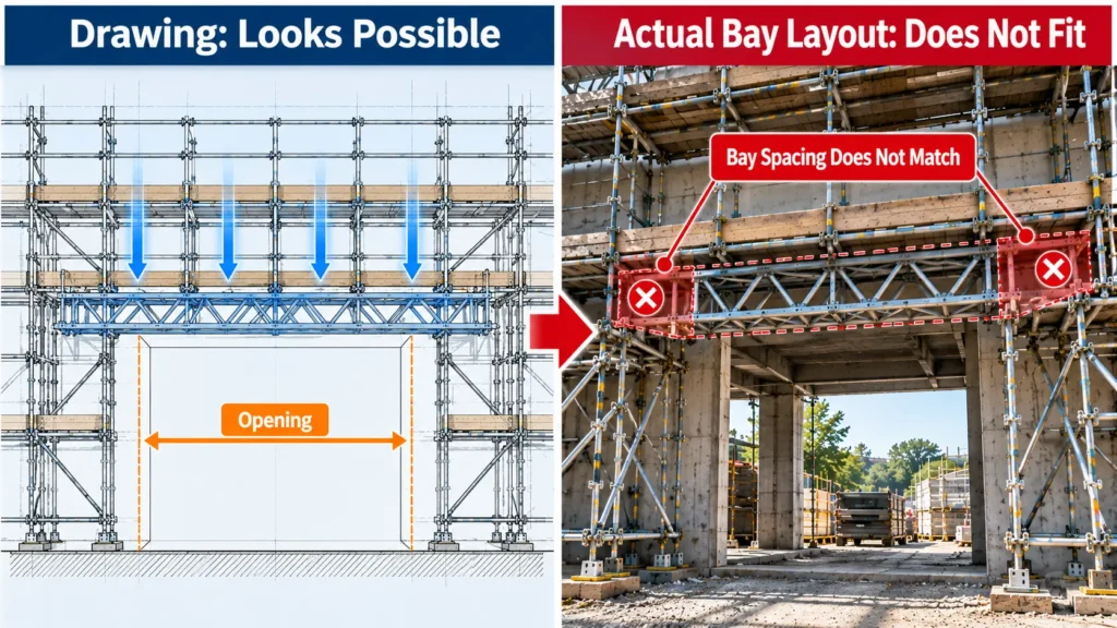
Original CAD Detail: Comparing Two-Span and Three-Span Bridge Frames
The following original CAD detail compares two scaffold bridge-frame arrangements: a two-span opening of 3,600 mm and a three-span opening of 5,400 mm, based on 1,800 mm scaffold bays. It helps illustrate why the opening width must be considered together with the positions of the supporting standards and the surrounding scaffold components.
When reviewing details like these, I would compare the opening dimensions with the actual scaffold bay layout, check where the bridge-frame reactions are carried, and consider whether the intended components and bracing can be assembled without interference. The drawing alone does not establish the capacity of the bridge frame, supporting standards, connections or foundations. Those checks depend on the selected scaffold system, manufacturer information, loading and project conditions.
Manufacturer Capacity Cannot Be Assumed
Bridge frames and other proprietary scaffold components do not have one universal capacity.
Allowable capacities and permitted configurations can differ between manufacturers, systems and individual components.
For that reason, a capacity used for one product should not automatically be applied to another product that appears similar.
The actual manufacturer documentation for the component and configuration being used should be checked as part of the project-specific design.
The same caution applies when components from different systems or manufacturers are considered.
HSE guidance in Great Britain identifies bridge scaffolds among scaffold structures that normally require bespoke design.
Under OSHA requirements in the United States, scaffolds must be designed by a qualified person and constructed and loaded in accordance with that design. OSHA also states that scaffold components must not be loaded beyond their maximum intended loads or rated capacities, whichever is less.
Those are U.S. requirements. Other jurisdictions use their own legislation, standards and guidance, so they should not be treated as universal rules.
Bracing, Standards and Stability Around the Opening
An opening can also affect parts of the scaffold that are not directly spanning the opening.
Bracing is one example.
A bridge, entrance or other interruption may interfere with the normal location of braces, ties or other structural elements. The surrounding scaffold therefore needs to be reviewed as a system rather than as a collection of independent components.
In my design work, I do not consider bracing separately from standards, horizontal members, platforms and ties. Their functions are different, but their locations and constraints interact.
The same principle applies at a bridged opening.
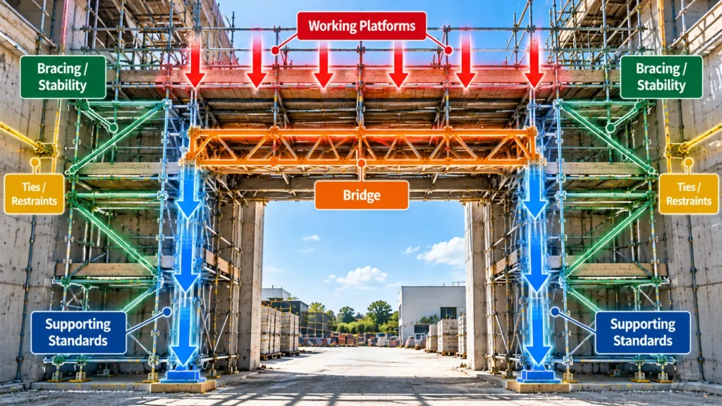
If the supporting standards receive increased load, their capacity and stability may become important. Buckling may also need consideration depending on the arrangement and loading.
The specific check depends on the scaffold system, component properties, geometry and design conditions, so there is no universal reinforcement detail that can be copied from one project to another.
Why Unreviewed Site Changes Are a Problem
Openings are often created because people need to move through the scaffold.
That practical need can create pressure on site to remove or rearrange components for convenience.
The problem is not simply whether tubes or other individual components are used. The problem is changing a structural arrangement without understanding what the changed components are supporting and where the loads will go afterward.
A site modification that looks small may alter:
- a vertical load path;
- support reactions;
- bracing;
- restraint;
- connection forces;
- local stability.
For U.S. work covered by OSHA, scaffold erection, movement, dismantling and alteration must be performed under the supervision and direction of a competent person qualified in those activities. This is separate from OSHA’s requirement that the scaffold itself be designed by a qualified person.
Requirements and defined roles vary by jurisdiction.
From a design perspective, the practical principle is clear: do not treat an opening as a field convenience that can be changed independently of the scaffold design.
What Should Be Clear on the Scaffold Drawing?
A drawing for a significant bridged opening should communicate enough information that the intended arrangement is not left to interpretation on site.
Depending on the project, useful information may include:
- opening width and height;
- relevant scaffold bay arrangement;
- location of the bridging component;
- standards supported above the opening;
- supporting standards or support locations;
- platform arrangement;
- required clearance;
- relevant bracing;
- relevant ties or restraint;
- relationship to entrances, traffic or access;
- references to project-specific calculations where required;
- manufacturer or component information where relevant;
- restrictions or notes needed to preserve the intended configuration.
Not every drawing needs every item in this list.
The objective is to show the information needed to communicate the approved design clearly.
A technically correct calculation is of limited value if the drawing allows the intended structural arrangement to be misunderstood during construction.
Practical Scaffold Bridging Review Checklist
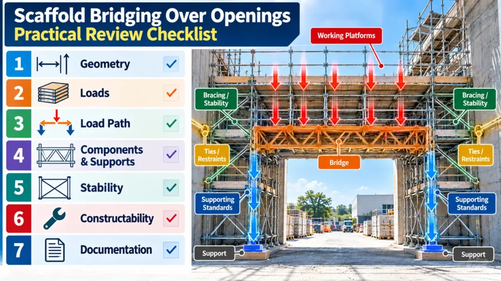
Before finalizing a scaffold arrangement over an opening, I would want the following questions answered.
Geometry
- □ Is the opening width confirmed?
- □ Is the required opening height confirmed?
- □ Does the proposed bridge fit the actual scaffold bay layout?
- □ Have plan, elevation and section conditions been coordinated where necessary?
- □ Are building projections and other obstructions accounted for?
Loads
- □ How much scaffold continues above the opening?
- □ How many working levels may contribute to the design condition?
- □ Are platform loading and material-loading conditions understood?
- □ Are unusual local loads identified?
Load Path
- □ Where do the loads from the interrupted standards go?
- □ What component transfers them across the opening?
- □ Where are the resulting reactions supported?
- □ Has the complete path to the supporting surface or structure been considered?
Components and Supports
- □ Is the actual scaffold system identified?
- □ Has applicable manufacturer information been checked?
- □ Have supporting standards been considered?
- □ Have base or supporting conditions been considered?
- □ Are connections relevant to the load path understood?
Stability
- □ Does the opening interfere with normal bracing?
- □ Does it affect tie locations or other restraint?
- □ Does the surrounding scaffold require additional structural review?
- □ Are buckling or local stability considerations relevant?
Constructability
- □ Can the arrangement actually be assembled using the intended components?
- □ Is adequate clearance maintained?
- □ Does it interfere with access, vehicles or material movement?
- □ Is the design clear enough to prevent unintended site modification?
Documentation
- □ Does the drawing clearly identify the intended arrangement?
- □ Are project-specific calculations referenced where necessary?
- □ Are component or manufacturer limitations communicated where relevant?
- □ Are assumptions and restrictions clear?
This checklist is a review aid, not a substitute for project-specific engineering.
FAQ
What is scaffold bridging over an opening?
Scaffold bridging is an arrangement used where normal vertical standards cannot continue through an opening. Loads from the scaffold above must be transferred through suitable bridging components to supports on each side and then continue to an adequate supporting surface or structure.
Can I use the same bridge-frame capacity for different scaffold manufacturers?
It should not be assumed. Component capacities and permitted configurations may differ between manufacturers and scaffold systems. The documentation applicable to the actual component and configuration should be checked.
Can workers change a bridged opening on site if more clearance is needed?
A structural arrangement should not be changed simply for convenience without the required review. Altering components around an opening can change load paths, bracing, support reactions and stability. Applicable local requirements and the approved project design should be followed.
Related Topics
A broader planning guide to openings, entrances and physical obstructions before considering structural bridging.

Scaffold Load Paths Explained: How Forces Travel Through the Structure — A planned guide to the broader load-path principles throughout a scaffold. A link will be added when it is published.
How openings affect tie planning and restraint locations.

Bracing constraints and stability around interrupted scaffold geometry.

Key Takeaways
- A scaffold opening is not only a geometric issue; it changes the normal load path.
- The designer should look at the scaffold above the opening, not only at the opening width.
- A bridging member is only one part of the structural path; supporting standards, stability and support conditions also matter.
- A configuration that can be drawn is not automatically structurally acceptable or practically buildable.
- Manufacturer-specific capacities and permitted configurations should be checked rather than assumed.
- Site changes around a bridged opening should not be treated as independent of the approved scaffold design.
Conclusion
The central question in scaffold bridging is not simply whether a member can span an opening.
It is whether the loads from the scaffold above have a clear, adequate and buildable path to suitable support.
In practice, this is also where drawings and structural thinking have to meet. A solution has to work not only as a concept, but as a scaffold that can actually be assembled in the intended location.
Official References
Occupational Safety and Health Administration (OSHA) — 29 CFR 1926.451, General Requirements for Scaffolds
Jurisdiction: United States
Supports: scaffold capacity, qualified-person design, loading in accordance with the design, rated-capacity limitations, supported-scaffold foundation requirements and alteration supervision.
OSHA — 29 CFR 1926.451
Health and Safety Executive (HSE) — Scaffolds
Jurisdiction: Great Britain
Supports: scaffold design information and guidance relating to beamed bridges and bridge scaffolds requiring bespoke design.
HSE — Scaffolds
Last Verified
Last Verified: September 2026
Regulations, official guidance and manufacturer documentation may change. Always confirm the current requirements applicable to the project location, scaffold system and intended use.
This article is general technical information and is not a substitute for project-specific engineering, applicable law, contract documents, project specifications, manufacturer instructions or competent professional review.
About the Author
ISHIDA DESIGN OFFICE brings more than 30 years of practical experience in Japan, specializing in scaffolding design, temporary works planning, CAD drafting, quantity estimation, and construction support.
Drawing on experience from residential, commercial, and industrial projects, he shares practical insights that emphasize not only sound engineering design but also buildability, safety, and real-world jobsite application.
At Scaffold Design Hub, he combines practical experience from Japan with official guidance and technical resources from government agencies, manufacturers, and industry organizations around the world to provide reliable, practical information for scaffold planning and design.
To learn more about the author and the design office, visit the About page. For questions or project inquiries, use the Contact page.