
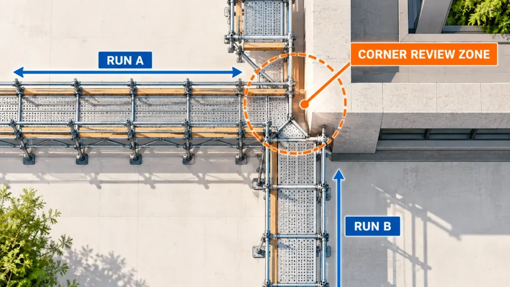
A building corner can look simple on a plan: one scaffold run meets another and the scaffold continues around the façade.
In practice, that change of direction can affect much more than the bay arrangement. Working-platform continuity, scaffold-to-building clearance, upright positions, guardrails, ties, bracing, worker movement and material handling can all become more difficult at the same location.
That is why I do not treat a building corner as just the end of one scaffold run and the beginning of another. It is a transition area that needs to be checked as part of the whole scaffold layout.
This article explains the practical issues I look for when reviewing scaffolding around building corners. It focuses on what should be checked rather than prescribing one universal corner detail, because the appropriate arrangement depends on the scaffold system, building geometry, project conditions, manufacturer information and applicable requirements.
A Corner Is More Than Two Scaffold Runs Meeting
The first mistake is to consider each elevation separately.
A scaffold layout may work along Elevation A. Another layout may work along Elevation B. But when those two arrangements meet, the corner itself can create a third problem.
For a building corner, I normally want to understand several conditions together:
- building dimensions and geometry;
- scaffold-to-building clearance;
- frame or upright positions;
- working-platform width and continuity;
- possible tie locations;
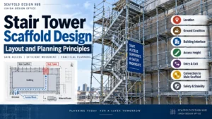
- access through and around the corner;
- obstructions or projections near the corner; and
- whether the proposed scaffold system can accommodate the geometry without creating an awkward local condition.
The dimension itself is not the whole issue. What matters is what happens when all these conditions meet at one point.
A clean-looking plan is useful, but the scaffold also has to work as a structure, a working platform and a route for people and materials.
Start With the Building, Not the Scaffold System
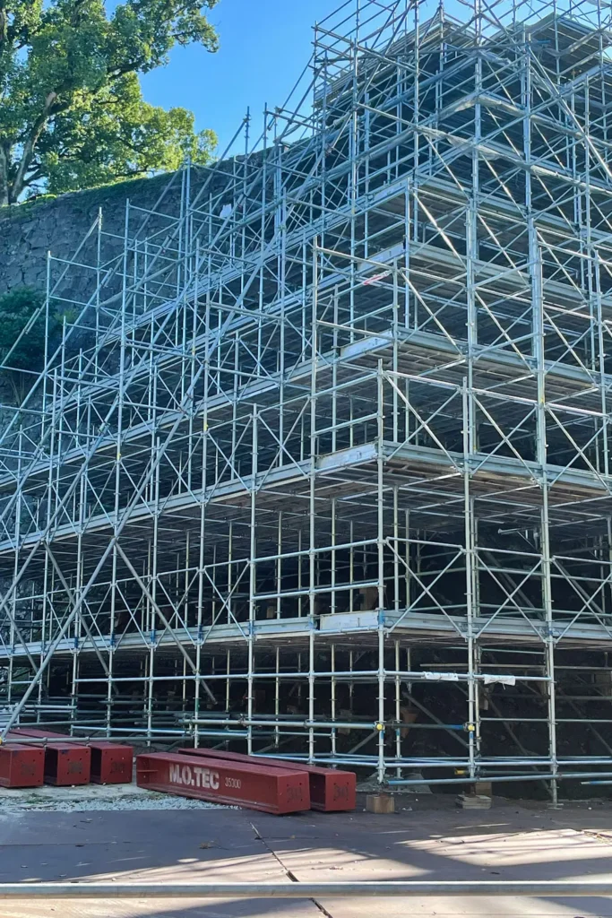
It is tempting to begin with standard bay lengths and try to make the building fit the scaffold module.
I prefer to understand the building geometry first.
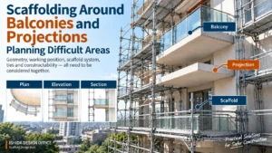
Where exactly is the corner? Is it really 90 degrees? Does the façade change position above or below it? Is there a column, balcony, sign, canopy, decorative feature or other projection close to the corner?
These questions can change the layout before the first scaffold bay is placed.
A regular 90-degree concrete building and an older façade with projections may both have a “corner” on the architectural plan, but they do not necessarily present the same scaffold problem.
This becomes even more important where architectural decoration, signs or façade features occupy the corner zone. The obstacle should be identified early rather than discovered after a regular scaffold grid has already been developed.
What Changes When the Scaffold Turns a Corner?
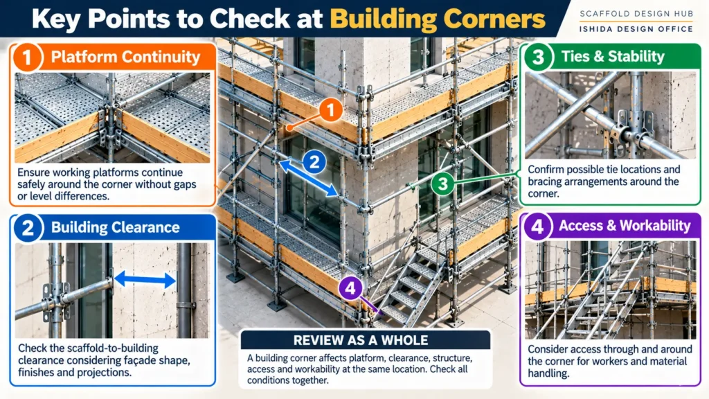
Platform continuity and gaps
One of the first things to check is the working platform.
Two scaffold runs can appear to meet correctly while leaving an awkward opening where the platform changes direction. A local adjustment can also create a platform width that is acceptable on the straight run but uncomfortable at the corner.
The corner therefore needs to be reviewed as a working area, not simply as intersecting grid lines.
For projects under U.S. OSHA requirements, 29 CFR 1926.451 contains specific platform construction provisions and even addresses locations where a scaffold platform changes direction, including turning a corner. OSHA also specifies requirements for platform decking and permissible gaps. These are U.S. requirements and should not be treated as universal dimensions for projects in other jurisdictions.
The broader design lesson applies regardless of jurisdiction: do not assume that platform continuity will solve itself because the main scaffold runs are correctly dimensioned.
From My Design Work: Platform Layout at Building Corners
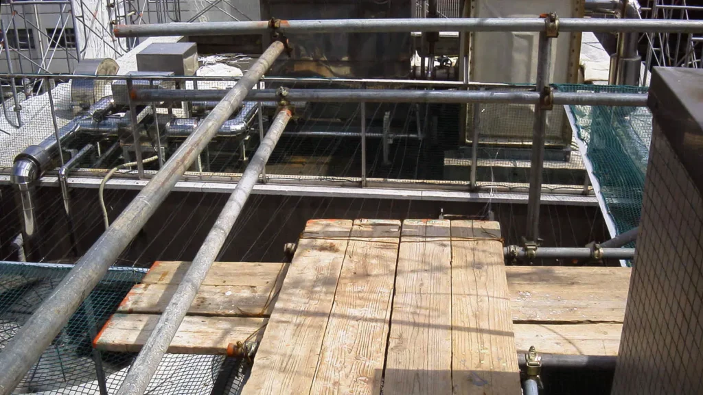
In my scaffold design work in Japan, arranging scaffold boards around building corners has sometimes been a challenging part of the layout process.
One of the points I pay particular attention to is how the scaffold boards fit together where two scaffold runs meet. The individual runs may look straightforward in plan, but the corner still needs to be reviewed for platform continuity and possible gaps.
This is why I consider the arrangement of the uprights and the working platforms together, rather than treating them as separate design questions.
Upright and frame interference
The next issue is structural geometry.
Depending on the scaffold system and the bay arrangement, posts, frames or other components from the two directions may compete for the same physical space.
Moving one component to solve the interference may then affect another condition—platform support, building clearance, tie location or the adjacent bay arrangement.
This is why I prefer to review the corner in plan before treating either elevation as final.
Scaffold-to-building clearance
Clearance should also be checked through the turn.
A reasonable distance from the façade along one elevation does not automatically mean that the working platform remains appropriately positioned around the corner.
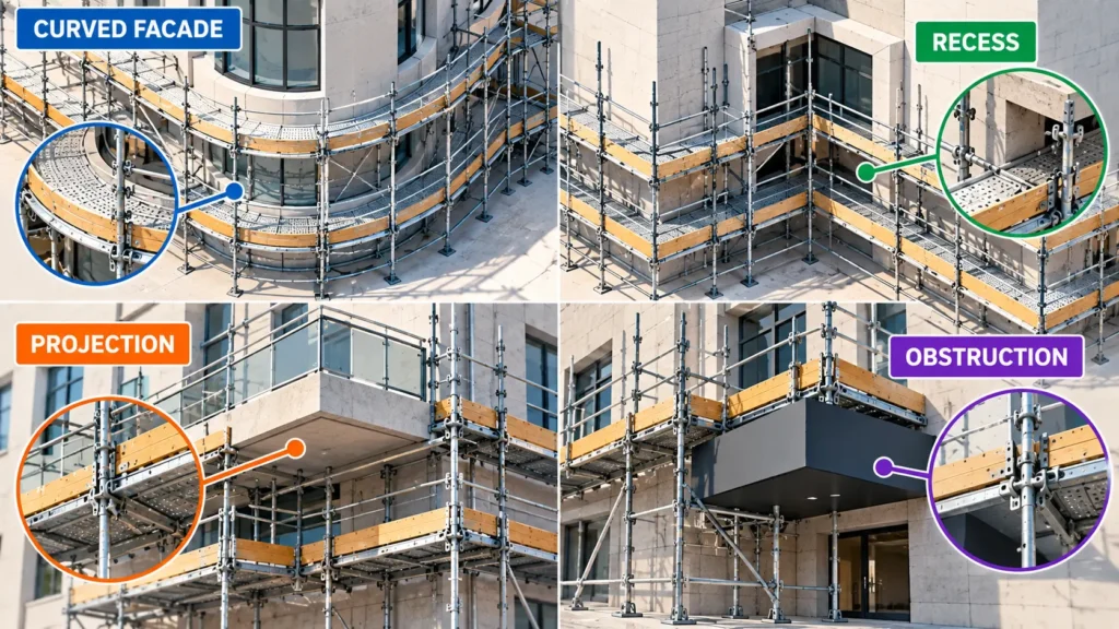
Irregular geometry can make the effective gap increase locally. Curved walls, recesses and projections make this more obvious, but even a nominally simple corner deserves a check.
If a larger local gap cannot be avoided, the response must be appropriate to the scaffold system, the work being performed and the applicable safety requirements. Local brackets or other system-compatible arrangements may sometimes be considered, but their suitability and structural implications must be verified rather than assumed.
Guardrails and edge protection
Corners can also create small open edges that are easy to miss on a plan.
A designer should look beyond the main outside guardrail line and ask whether the change in platform direction creates an exposed edge or another fall hazard.
The applicable fall-protection requirements depend on jurisdiction. For example, OSHA requires guardrail systems along open sides and ends when its scaffold fall-protection provisions apply.
The drawing should make the intended protection understandable rather than relying on someone on site to interpret an ambiguous corner.

Standard System Components or Local Adjustment?
Where possible, a regular system layout has obvious advantages. Standard components and predictable geometry make the arrangement easier to understand and can make structural verification more straightforward.
But buildings do not always cooperate.
A corner may require a different bay arrangement, a system-compatible bracket, or another properly engineered local solution. Tube-and-coupler components may also be used in some scaffold configurations and jurisdictions.
What should be avoided is treating an improvised connection as structurally acceptable simply because it can physically be assembled.
When a local arrangement changes how loads are transferred or how components are connected, its structural adequacy needs to be established using the relevant design information, manufacturer data and engineering requirements.
This article deliberately stops short of giving a universal corner connection detail. There is no single detail that can safely represent every scaffold system, building geometry and jurisdiction.
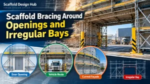
Irregular, Curved and Obstructed Corners
Not every building turns through a clean 90 degrees.
Curved façades are a good example. Trying to force a modular scaffold system to follow every small change in the building line can produce an unnecessarily complicated layout.
In practice, it can be more useful to distinguish between the main structural scaffold arrangement and the local interface with the building. The exact solution depends on the system and project conditions, but the important point is to recognise that these are related yet different design questions.
The same applies to irregular corners.
Possible constraints include:
- curved façades;
- recessed walls;
- changing building lines;
- columns;
- balconies;
- architectural decoration;
- signs;
- canopies;
- pipes and building services; and
- other projections.
These features should be identified before the corner layout is finalised.
There is also a commercial reality. A technically possible arrangement may be unnecessarily complicated or expensive to construct. Constructability and project constraints therefore belong in the discussion, provided that cost never replaces the required structural and safety checks.
Do Not Separate Corner Layout From Ties and Stability
A corner is primarily a geometric problem only until geometry begins to affect the structural arrangement.
Tie positions are one example.
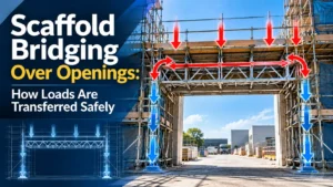
A regular tie pattern developed for a long straight elevation may encounter a window, projection, façade feature or unsuitable fixing location near the corner. The designer therefore needs to confirm that the proposed tie locations correspond to locations where ties can actually be installed.
Bracing also needs to be considered as part of the whole scaffold rather than as an isolated drawing symbol.
If a corner arrangement changes the continuity or behaviour of the scaffold, the designer should check whether the assumed structural arrangement remains valid. Where additional local restraint or reinforcement is necessary, it should be based on an appropriate structural assessment rather than added simply because “corners need more bracing.”
This distinction matters.
More components do not automatically mean a better design. The correct structural arrangement is the one supported by the relevant design conditions and verification.
The Drawing Can Work While the Site Still Struggles
This is where corner planning becomes particularly practical.
A scaffold can be geometrically correct and still be difficult to use.
Passing space
Corners naturally change the walking direction. If the available platform becomes narrow at the same location, workers may find it difficult to pass each other.
That issue is easy to underestimate when reviewing a CAD plan because a drawing normally shows components, not two people carrying tools or materials.
Where the work requires regular movement around the building, usable working width through the corner deserves deliberate attention.
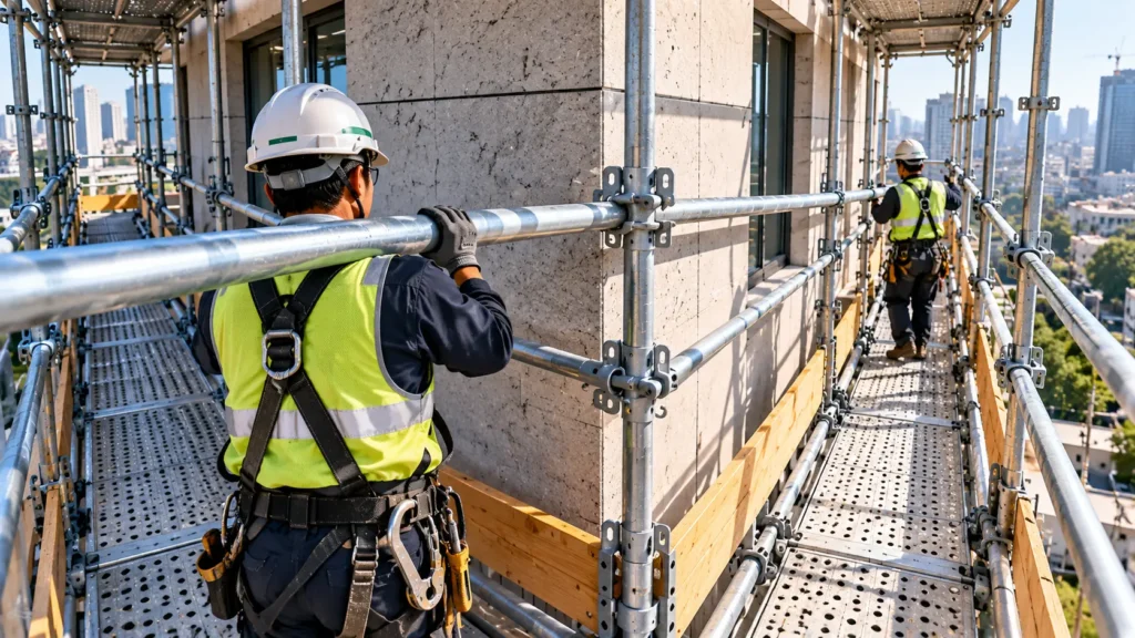
Moving long materials
Long materials make the problem more obvious.
A person carrying a long scaffold component, pipe or other construction material needs enough space not only to walk but also to turn.
Several narrow corners along a transport route can slow movement significantly. That can become a productivity and programme issue even when every individual scaffold bay looks acceptable on the drawing.
This is one reason I consider workability as well as geometric fit.
Making the designer’s intent clear
There is another lesson from practical drawing work: a correct design is not enough if the important detail is easy to misinterpret.
I have seen situations where the intended corner arrangement was not communicated clearly enough and the site arrangement did not reflect the level of attention to the corner that the drawing required.
For that reason, I would rather make an unusual corner condition obvious on the drawing than leave it to site interpretation.
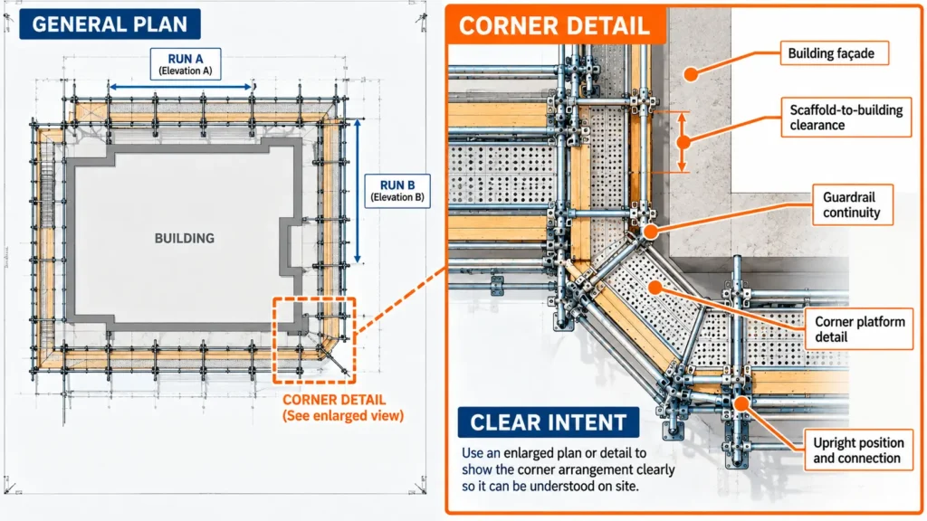
A local plan enlargement, section, detail, note or clearly referenced drawing can sometimes communicate more effectively than adding more general notes to the sheet.
What I Would Show Clearly on the Drawing
The required information depends on the project, but a corner review should consider whether the drawing makes the following clear:
- building geometry around the corner;
- scaffold grid and upright/frame positions;
- working-platform continuity;
- significant changes in platform width;
- scaffold-to-building relationship;
- nearby projections and obstructions;
- intended access and circulation;
- relevant tie locations;
- bracing where it affects the corner arrangement;
- edge protection where required; and
- any location requiring a separate detail or engineering review.
Not every corner needs a complicated detail.
The purpose is to identify the corners that do.
From My Design Work: Why Corner Details Matter
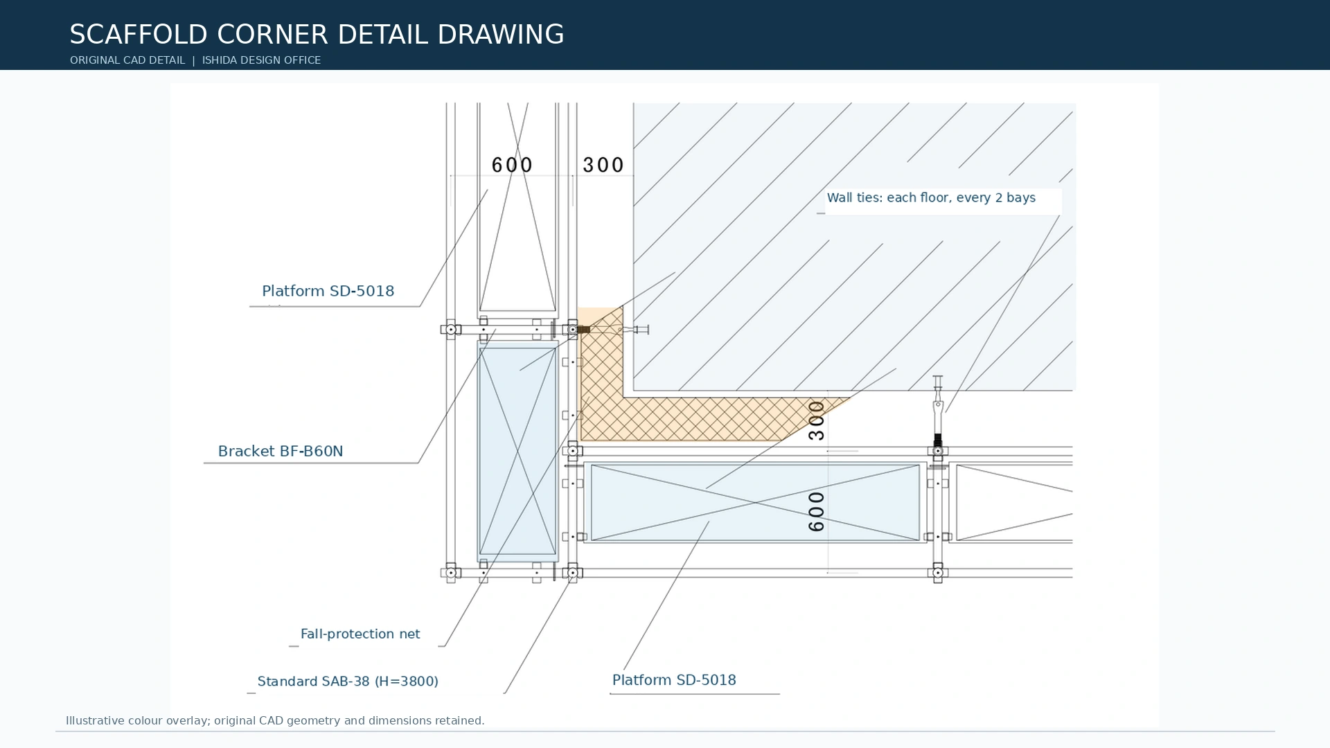
When designing scaffolding around building corners, I place particular importance on checking the positions of the uprights in the plan drawing.
The arrangement of the uprights is closely related to how the working platforms can be laid out at the corner. This is especially important when reviewing the fit of scaffold boards and identifying possible gaps.
My experience has also taught me the importance of providing a clear corner detail drawing. A focused detail can make the intended arrangement easier to understand than relying only on the general scaffold plan.
A Practical Building Corner Review Checklist
Before finalising a scaffold layout around a building corner, I would check the following.
Building geometry
- Is the corner actually 90 degrees?
- Does the building line change at another level?
- Are there recesses, curves or projections?
- Are signs, balconies, canopies, services or decorative features present?
Scaffold geometry
- Do the two scaffold runs physically coordinate?
- Are frames or uprights interfering?
- Does the selected system accommodate the corner?
- Is a local non-standard arrangement being introduced?
Working platform
- Is platform continuity maintained?
- Are there unintended gaps?
- Does the usable width reduce at the corner?
- Is edge protection addressed where required?
Building interface
- Does scaffold-to-building clearance remain appropriate through the corner?
- Does the façade geometry create a larger local gap?
- Are local interface components being used within their intended conditions?
Structure and stability
- Are practical tie locations available?
- Does the corner affect the assumed bracing arrangement?
- Does any local adjustment require structural verification?
- Have manufacturer information and project design requirements been checked?
Constructability and use
- Can workers move around the corner comfortably?
- Can workers pass where the work requires it?
- Can long materials be transported through the corner?
- Is the intended arrangement clear enough for the site team to build correctly?
A checklist like this does not replace engineering. Its purpose is to stop a seemingly small corner condition from being overlooked during the wider scaffold layout review.
Regulatory Requirements Depend on Location
Scaffold requirements vary by country, jurisdiction, scaffold type and project.
For example, U.S. OSHA 29 CFR 1926.451 contains requirements for scaffold capacity, platform construction, access, fall protection and supported scaffolds. It also specifically addresses platform arrangements where the platform changes direction at a corner.
Those provisions should not be copied into a project governed by another jurisdiction and presented as universal rules.
For every project, check the applicable legislation and standards, project specifications, engineer requirements, scaffold-system documentation and manufacturer instructions.
The practical planning principles in this article help identify what needs attention. The governing requirements determine what is acceptable for the specific project.
FAQ
Why are building corners difficult in scaffold layout?
Because two scaffold runs that work independently can create platform gaps, component interference, changing building clearance, awkward access or structural coordination issues when they meet.
Should scaffold bays simply follow the building dimensions around the corner?
Not automatically. Building geometry is only one input. Working-platform requirements, component positions, access, ties, structural behaviour, manufacturer requirements and site constraints may also affect the layout.
Can brackets be used to close a gap between the scaffold and the building?
They may be appropriate in some scaffold systems and project conditions, but their use should follow the relevant system or manufacturer information and structural requirements. A bracket should not be treated as a universal solution to every corner gap.
Do scaffold ties need special attention near corners?
Yes. Corners, openings, projections and façade changes can make regular tie locations impractical. The actual available fixing locations and the structural design requirements should therefore be checked rather than assuming a regular pattern will continue unchanged.
Should worker movement be considered during scaffold design?
Yes. A scaffold is not only a structural arrangement. Workers need to access the work area and, depending on the project, move tools and materials along the platforms. Narrow or poorly arranged corners can reduce practical usability.
Is there one standard detail for every scaffold building corner?
No. The appropriate detail depends on building geometry, scaffold system, loading and structural conditions, manufacturer information, project requirements and the applicable jurisdiction.
Related Topics
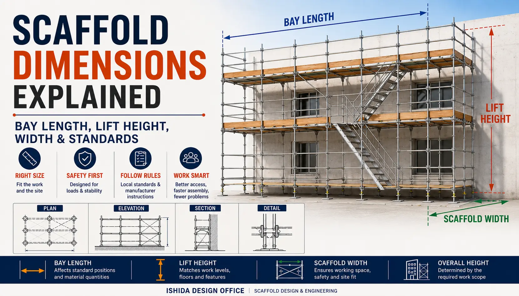
Scaffold Dimensions: How to Read Width, Height and Bay Length
Understanding basic scaffold dimensions and bay layout helps explain why standard dimensions do not always resolve a building corner.
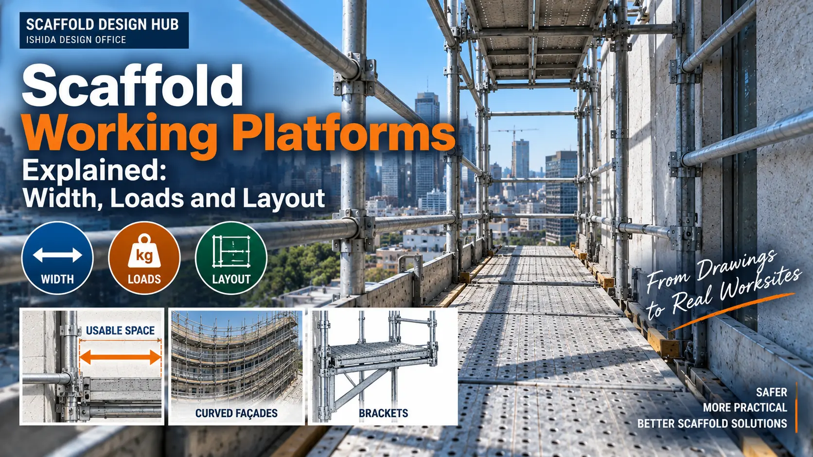
Scaffold Working Platforms Explained: Width, Loads and Layout
Scaffold working-platform layout is especially relevant when a corner affects usable platform width, continuity or worker movement.
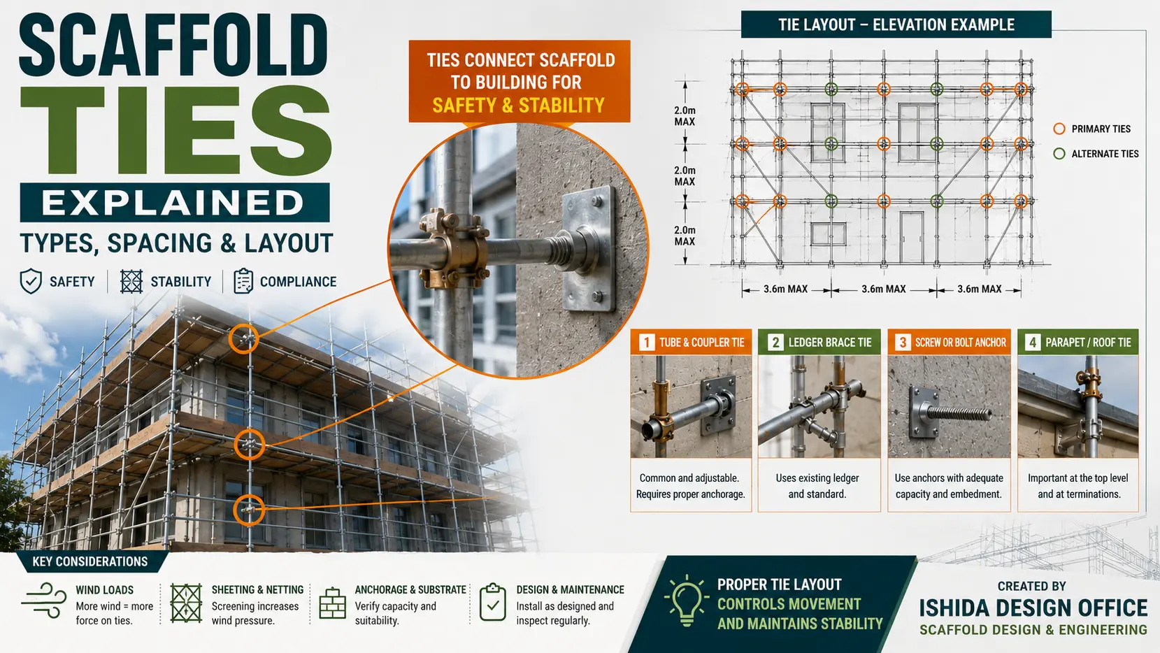
Scaffold Ties
Scaffold tie planning is important when corner geometry, openings or façade features affect practical tie locations.
Scaffold Constructability
Scaffold constructability extends the discussion from geometric layout to whether the proposed scaffold can be built and used efficiently on site.

Scaffold Returns at Building Corners: Layout and Design Details
A separate article on scaffold returns at building corners will explore the return arrangement in greater detail, building on the broader corner-planning principles explained here.
Key Takeaways
- A building corner should be reviewed as a transition zone, not simply where two straight scaffold runs meet.
- Building geometry, platform continuity, scaffold clearance, component positions, access, ties and stability can interact at the same corner.
- A geometrically correct layout may still create problems for worker movement or material handling.
- Irregular, curved or obstructed façades often require more than simply applying standard bay dimensions.
- Local adjustments should be structurally verified where they change connections or load transfer.
- Important corner conditions should be communicated clearly on the drawing rather than left to site interpretation.
- Specific legal dimensions and construction requirements must be checked against the jurisdiction, project and scaffold system.
Conclusion
Good scaffold corner planning is not about finding a clever way to make two scaffold runs meet.
It is about making sure the corner works as part of the complete scaffold: geometrically, structurally and practically.
Check the building first. Then check the platform, clearance, component positions, ties, stability and the way people and materials will actually move through the area.
If the corner needs an unusual arrangement, make that intention clear on the drawing and verify the solution against the relevant project requirements.
The next level of this subject is the scaffold return itself—how the turning scaffold arrangement should be coordinated and detailed. That deserves a separate technical article rather than being compressed into a general corner-planning guide.
Official References
Occupational Safety and Health Administration (OSHA) — 29 CFR 1926.451, General Requirements for Scaffolds
Jurisdiction: United States
Used for: scaffold platform construction, platform direction changes at corners, supported scaffold requirements and fall-protection references.
Verification status: Primary government source checked September 2026.
OSHA Scaffolding eTool — General Requirements for Scaffolds
Jurisdiction: United States
Used for: supporting explanation of platform construction, working width and supported scaffold requirements.
Verification status: Primary government guidance checked September 2026.
Last Verified: September 2026
Regulations, official guidance and manufacturer documentation may change. Always confirm the current requirements applicable to the project location, scaffold system and intended use.
This article is general technical information and is not a substitute for project-specific engineering, applicable law, contract documents, project specifications, manufacturer instructions or competent professional review.
About the Author
ISHIDA DESIGN OFFICE brings more than 30 years of practical experience in Japan, specializing in scaffolding design, temporary works planning, CAD drafting, quantity estimation, and construction support.
Drawing on experience from residential, commercial, and industrial projects, he shares practical insights that emphasize not only sound engineering design but also buildability, safety, and real-world jobsite application.
At Scaffold Design Hub, he combines practical experience from Japan with official guidance and technical resources from government agencies, manufacturers, and industry organizations around the world to provide reliable, practical information for construction professionals.
To learn more, visit the About page. For questions or project inquiries, please use the Contact page.