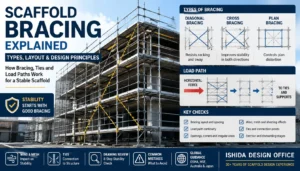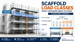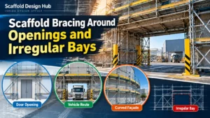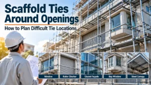
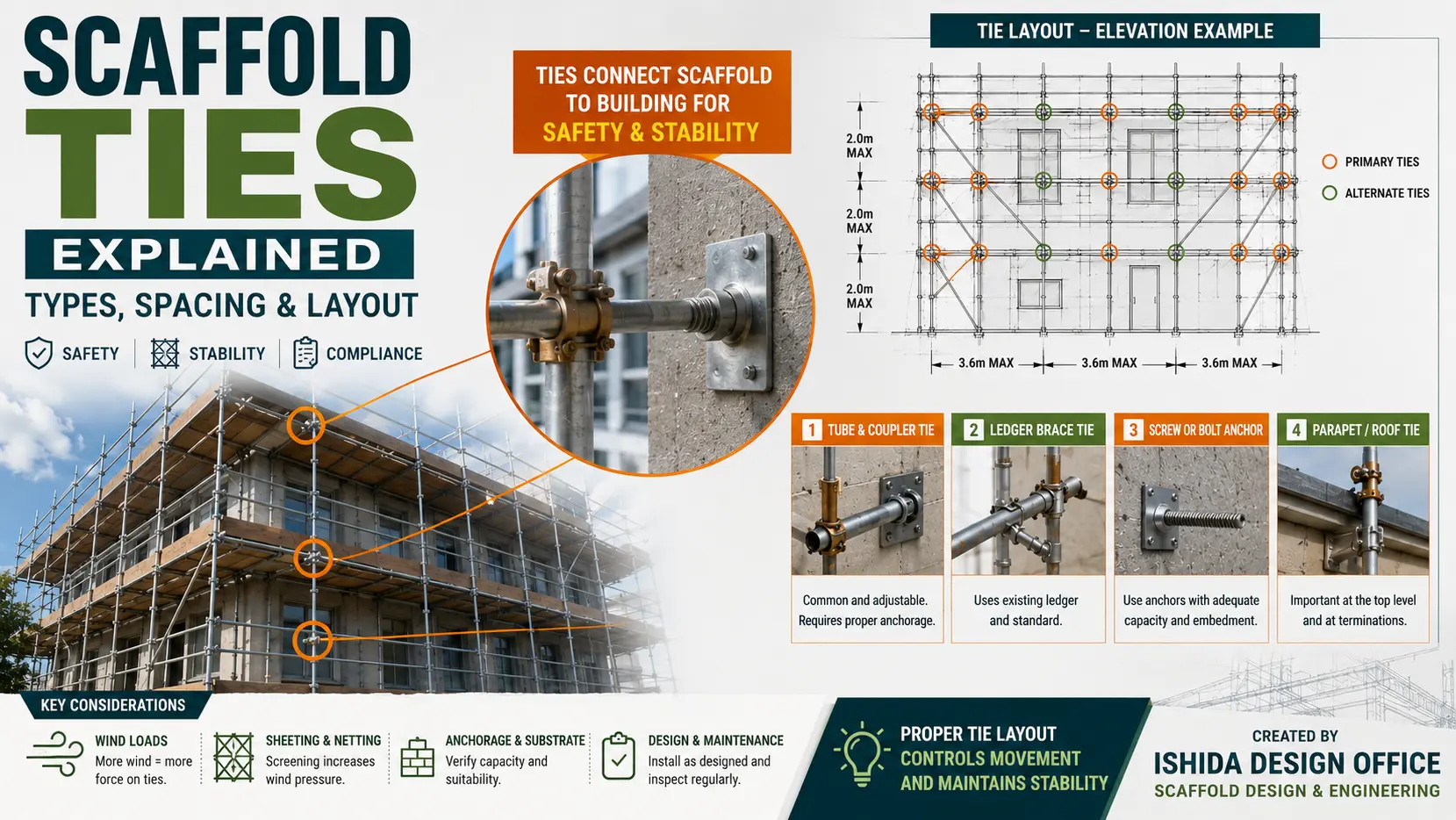
A scaffold can look straight, level, fully boarded and professionally erected—and still have a serious stability problem.
When I review a scaffold elevation, one of the first things I look at is the tie layout.
Not just the number of ties.
I want to know:
- Where are they?
- What are they connected to?
- What happens at the ends?
- What happens at the top?
- What happens around windows and entrances?
- Has sheeting or netting been added?
- Can the anchors actually be installed where the drawing shows them?
- Does the scaffold on site still match the scaffold that was designed?
After more than 30 years working with scaffold planning, drawings, quantity take-offs and temporary works, I have learned one lesson that I consider especially important:
Do not choose scaffold tie spacing from one number alone.
A safe tie arrangement depends on the scaffold configuration, the forces acting on it, and the structure receiving those forces.
In other words:
Scaffold → Tie → Anchor → Building
Every part of that load path has to work.
This guide explains the main types of scaffold ties, how spacing should be understood, what regulations actually tell us, how wind and sheeting change the situation, and how I review a tie layout before accepting it.
My goal is not to give you another table of numbers to copy.
My goal is to help you understand why the ties are where they are.
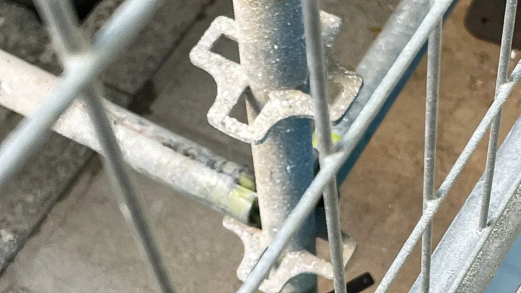
Safety note: Requirements vary by country, jurisdiction, scaffold system and project. Always follow local regulations, project specifications, the approved scaffold design and the scaffold manufacturer’s current instructions. Non-standard configurations may require assessment or design by a competent or appropriately qualified person.
Quick answer: Scaffold tie spacing should never be selected from one universal number. The correct layout depends on the scaffold system, height, width, bay and lift geometry, wind exposure, sheeting or netting, anchor capacity, substrate, manufacturer guidance and applicable local requirements.
What Is a Scaffold Tie?
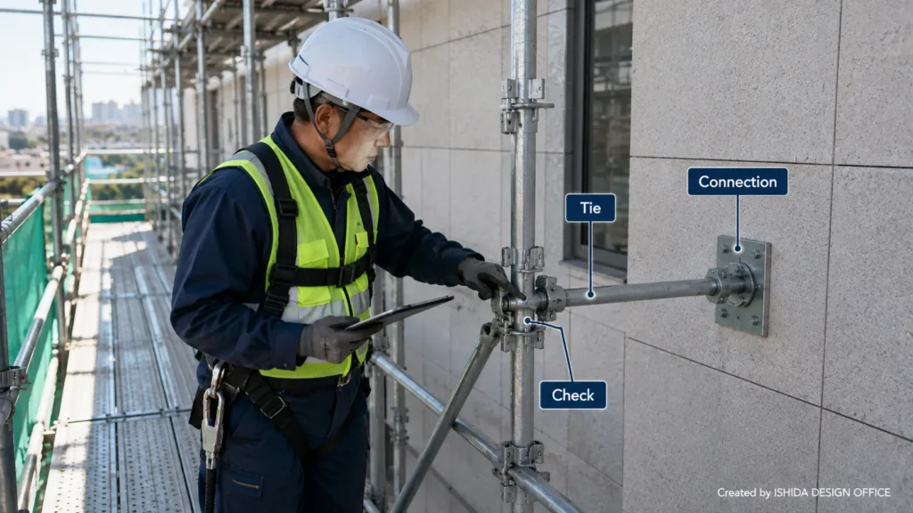
A scaffold tie is a restraint that connects a supported scaffold to a building or another suitable structure. Its job is to help control movement and maintain stability.
That sounds simple.
But a scaffold tie is not just a tube running toward a wall.
It is part of a structural load path:
Scaffold → Tie Member → Connection or Anchor → Permanent Structure
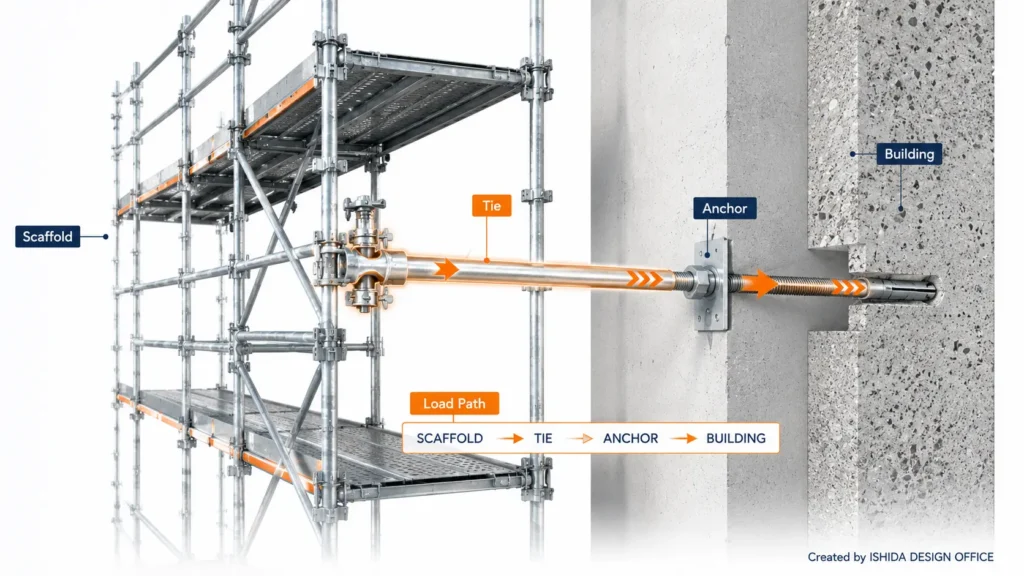
If one link is weak, the existence of a tie symbol on a drawing does not make the scaffold stable.
Depending on the configuration, ties can contribute to resistance against:
- movement toward or away from the building;
- lateral sway;
- displacement;
- overturning;
- wind-induced forces;
- forces caused by eccentric platforms;
- forces introduced by special scaffold features.
In the United States, OSHA requires supported scaffolds with a height-to-base-width ratio greater than 4:1 to be restrained from tipping by guying, tying, bracing or equivalent means. OSHA also requires restraint where eccentric loading could cause tipping.
The important concept is:
restrained from tipping.
That is the function.
Spacing is only one part of achieving that function.
Terminology Can Be Misleading
Depending on the country, contractor or scaffold system, you may hear:
- scaffold tie;
- wall tie;
- tie-in;
- anchor tie;
- building tie;
- through tie;
- reveal tie;
- restraint.
I would not spend too much time arguing over terminology.
The better question is:
How does this connection transfer force from the scaffold into the permanent structure?
If that question cannot be answered clearly, I would keep checking.
Why Scaffold Ties Matter More Than They Look
Scaffold ties are relatively small components, but their influence on the overall scaffold can be significant. A missing or poorly positioned tie can change how lateral forces move through several bays and lifts.
When people first look at a scaffold drawing, their attention often goes to:
- platform width;
- bay length;
- lift height;
- stairs;
- ladders;
- guardrails;
- access.
Those are all important.
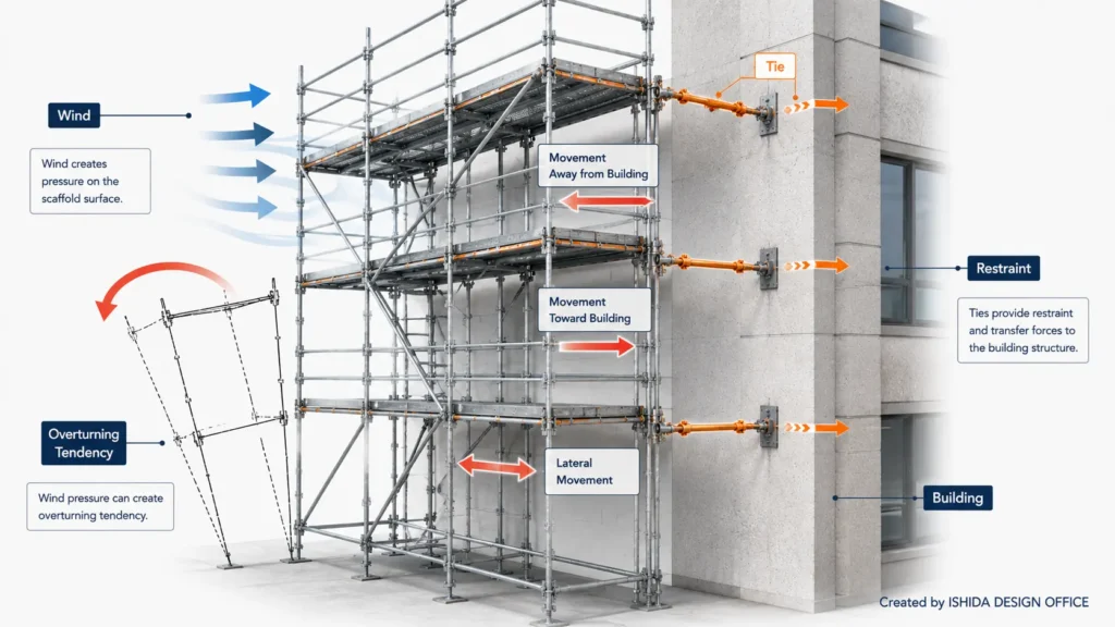
But a scaffold can have all of those features correct and still be poorly restrained.
Tie planning affects:
- overall stability;
- wind resistance;
- erection sequence;
- dismantling sequence;
- allowable scaffold geometry;
- façade access;
- anchor quantity;
- temporary alterations;
- inspection;
- drawing coordination;
- cost;
- programme.
HSE advises that scaffolds should be braced and tied into a permanent structure or otherwise stabilised. It also says ties should be installed as the scaffold is erected and removed only in stages during dismantling. If one has to be removed to allow work to continue, equivalent restraint should be provided nearby.
This is why I do not treat the tie layout as a decorative layer added at the end of a scaffold drawing.
It is part of the scaffold concept from the beginning.
Main Types of Scaffold Ties
There is no single tie detail suitable for every façade. The appropriate connection depends on the building, scaffold system, available structural locations, forces and approved design.
The names also vary between countries, so the categories below are best understood as stability concepts, not universally interchangeable standard details.
1. Through Ties
A through tie passes through a suitable building opening and is restrained on the opposite or internal side.
Possible locations may include:
- windows;
- doors;
- structural openings.
Where properly designed, the advantage is a relatively direct mechanical load path.
The practical problem is coordination.
The ideal tie grid rarely matches every opening perfectly.
A tie shown at grid intersection X-5 is not useful if the real building has no suitable structural opening there.
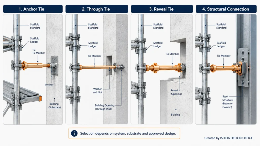
2. Anchor Ties
An anchor tie connects the scaffold to an anchor installed into a suitable structural substrate.
Common possibilities include:
- reinforced concrete;
- appropriate masonry;
- suitable structural members;
- other approved structural substrates.
But there are really two separate checks:
- Is the scaffold-side tie arrangement adequate?
- Is the anchor and receiving structure adequate?
A perfectly good scaffold tube connected to an unsuitable anchor is still a poor connection.
3. Structural Member or Column Ties
Where suitable structural columns, beams or other members are available, the scaffold may be connected directly to them using an approved detail.
This can sometimes reduce the need to drill finished façades.
But the connection still has to transfer the required forces.
The fact that a member is made of steel does not automatically make every connection to it suitable.
4. Reveal or Opening Restraints
Some scaffold arrangements use building openings or reveals as part of the restraint system.
The important point is that the mechanism needs to be understood.
Simply wedging a tube into a convenient space should never be confused with a properly designed restraint.
5. Rakers, Guys and Buttress Bays
Sometimes direct ties to the building are limited or impossible.
Alternative stability systems may include:
- rakers;
- guys;
- buttress bays;
- engineered freestanding arrangements.
HSE specifically warns that a single unbraced tube does not normally provide adequate raker stability; rakers need appropriate bracing and footing.
These alternatives should not be improvised substitutes for missing ties.
Practical Comparison
| Type | Typical Use | Main Advantage | Main Point to Check |
|---|---|---|---|
| Through tie | Building openings | Clear load path | Opening availability |
| Anchor tie | Concrete or masonry façade | Flexible positioning | Anchor and substrate |
| Structural member tie | Columns / frames | Uses existing structure | Connection detail |
| Reveal/opening restraint | Suitable openings | Can avoid drilling | Actual restraint mechanism |
| Raker / buttress | Limited wall ties | Alternative stability | Bracing, foundation, design |
Scaffold Tie Spacing: There Is No Universal Number
Tie spacing is one of the most misunderstood parts of scaffold work. Regulations and manufacturer manuals may give maximum intervals or standard patterns, but those figures should not be treated as a universal grid.
When someone asks me:
“What is the correct scaffold tie spacing?”
I usually want to ask:
“For which scaffold?”
Before I judge spacing, I want to know:
- scaffold system;
- scaffold width;
- total height;
- bay length;
- lift height;
- façade geometry;
- wind exposure;
- sheeting or netting;
- loading bays;
- cantilevers;
- hoists;
- temporary roofs;
- tie type;
- anchor capacity;
- substrate;
- manufacturer guidance.
One number without those conditions can be dangerous.
United States — OSHA Baseline
OSHA 29 CFR 1926.451(c)(1) gives a clear baseline for certain supported scaffolds.
Where the height-to-base-width ratio exceeds 4:1, the scaffold must be restrained by guying, tying, bracing or equivalent means. Where manufacturer recommendations are not being followed, OSHA sets the following repeated vertical intervals:
| Scaffold Width | Vertical Repetition |
|---|---|
| 3 ft (0.91 m) or less | 20 ft (6.1 m) or less |
| Greater than 3 ft (0.91 m) | 26 ft (7.9 m) or less |
OSHA also requires:
- restraint at each end;
- horizontal intervals not exceeding 30 ft (9.1 m);
- the top restraint positioned so the completed scaffold does not extend more than the applicable 4:1 height above it;
- additional restraint where eccentric loads could cause tipping.
These are useful numbers.
But they do not mean:
“Every scaffold should use a 30 ft × 26 ft tie grid.”
That would be a serious oversimplification.
United Kingdom — HSE Approach
HSE focuses on adequate strength, rigidity and stability.
For proprietary systems, HSE says scaffolds should be erected and tied according to the manufacturer’s instructions. It also makes clear that scaffolds outside recognised standard configurations or applicable manufacturer guidance may require bespoke calculation by a competent person.
I like this logic because it is easy to remember:
Recognised standard configuration → follow the recognised configuration.
Proprietary system → follow the manufacturer’s configuration.
Outside those conditions → verify by design.
That is a much safer mindset than searching for one spacing number on the internet.
Australia — Designer, Manufacturer and Site Conditions
Safe Work Australia’s scaffold guidance says tie methods and spacing should follow the instructions of the manufacturer, designer or supplier. If it is not practical to position the ties as instructed, the scaffold designer, manufacturer, supplier or engineer should be consulted.
The same guidance specifically identifies situations where additional ties may be required, including:
- sheeted or netted scaffolds;
- loading platforms;
- lifting appliances;
- rubbish chutes.
That is important because those are exactly the kinds of changes that happen after erection.
Australia also requires attention to the relevant state or territory regulator; Safe Work Australia develops model guidance but does not itself enforce each jurisdiction’s WHS laws.
Japan — Useful Regulatory Reference, but Not a Universal Grid
Japanese regulations use their own scaffold classifications.
Official Japanese labour-authority material summarising Article 570 identifies wall-tie spacing for specified scaffold categories, including approximately:
- single-pole tube scaffold: 5 m vertically and 5.5 m horizontally;
- frame scaffold: 9 m vertically and 8 m horizontally.
Those are useful legal reference values for the categories to which they apply.
But I would not convert them into:
“The Japanese rule for every scaffold is 5 m × 5.5 m.”
It is more complicated than that, especially for proprietary wedge-lock systems and special configurations.
Japanese guidance also specifically calls attention to the treatment of wedge-lock scaffolds under Article 570.
This is one reason I prefer to separate:
regulatory maximums
from
actual design layout.
Maximum Spacing Is Not the Same as a Designed Tie Layout
This is probably the most important distinction in the entire article.
A regulatory maximum answers:
How far apart may restraints be under the conditions of this particular rule?
A scaffold design asks:
Where do the ties need to be so that this particular scaffold remains stable under the actual design conditions?
Those questions are related.
They are not identical.
Imagine a simple scaffold elevation with a clean regular tie grid.
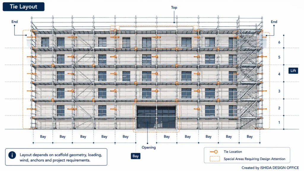
Now add:
- debris netting;
- solid sheeting;
- a loading bay;
- two large entrances;
- a stair tower;
- a hoist;
- a bridge;
- a cantilever;
- an exposed return;
- a temporary roof.
The scaffold may still look similar in elevation.
Its structural behaviour may be very different.
A project-specific design might therefore require:
- additional ties;
- closer spacing;
- stronger anchors;
- different tie positions;
- special edge ties;
- different corner arrangements;
- buttress bays;
- additional bracing.
This is why a perfectly uniform tie grid can sometimes make me cautious.
Real buildings are rarely perfectly uniform.
A Simple Way to Think About Tie Demand
You do not need to perform a complete scaffold calculation to understand why increasing spacing matters. A simple tributary-area concept is enough to make the basic relationship clear.
For a regular grid:
where:
- = approximate façade area associated with one tie;
- = horizontal tie spacing;
- = vertical tie spacing.
If a simplified pressure acts over that area:
where is a simplified conceptual horizontal action.
This is not a complete structural calculation.
Real design may need to include:
- regional wind velocity;
- terrain;
- height;
- pressure coefficients;
- local corner effects;
- shielding;
- sheet permeability;
- scaffold geometry;
- load combinations;
- tension and compression;
- tie-member capacity;
- anchor capacity;
- substrate strength;
- applicable safety or partial factors.
But the simplified relationship helps explain one practical truth:
If you significantly increase the area associated with one tie, you can significantly increase the demand on that connection.
That is why removing “only one tie” can matter more than it appears.
I use this simple relationship to understand the problem.
I do not use it to certify the scaffold.
This work must be carried out under the supervision of a competent or appropriately qualified person according to applicable local regulations and design standards.
The Anchor and the Building Are Part of the Tie System
One of the most common conceptual mistakes is checking the scaffold side of the connection while ignoring the building side.
People check:
- the tube;
- the coupler;
- the tie fitting.
But the tie is only useful if the permanent structure can receive the load.
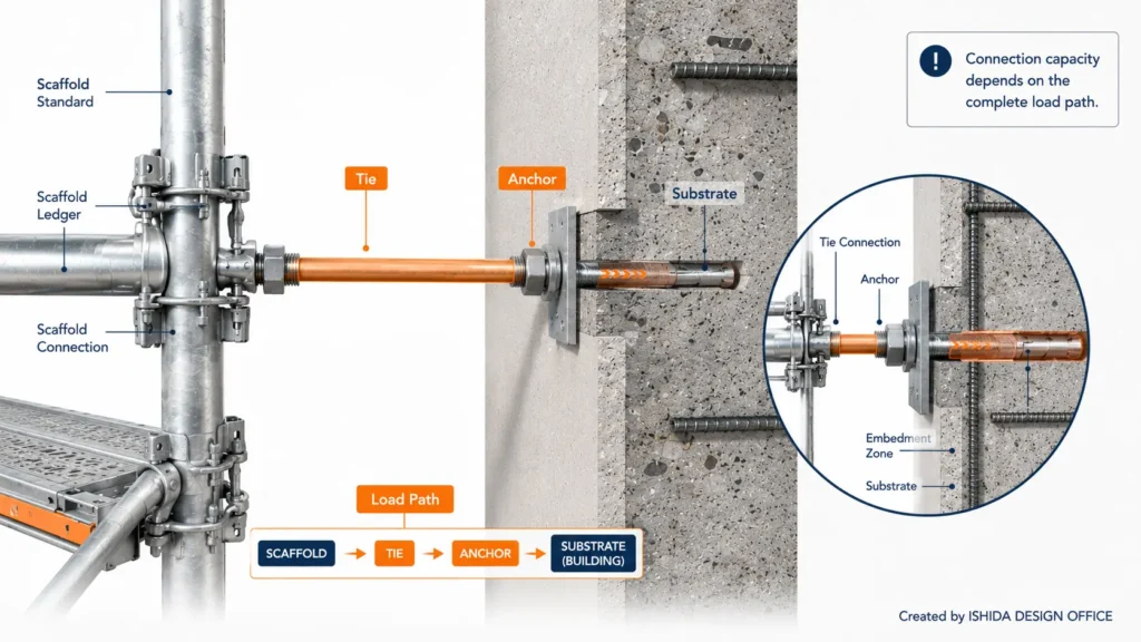
Before accepting an anchor arrangement, I want to understand:
- What is the substrate?
- Reinforced concrete?
- Masonry?
- Structural steel?
- Another approved structural member?
- What anchor system is specified?
- What embedment is required?
- What edge distance is available?
- What spacing is required between anchors?
- Is the substrate deteriorated?
- Is testing required?
- Does the anchor manufacturer’s documentation cover this application?
Safe Work Australia’s guidance gives particularly detailed advice on scaffold anchoring and says the designer, manufacturer, supplier or engineer should be consulted when ties cannot be placed in accordance with the intended arrangement.
For me, the practical lesson is simpler:
A wall is not a line in CAD.
The drawing may show a clean concrete line.
The real building may have:
- tile;
- render;
- insulation;
- waterproofing;
- hollow masonry;
- old brick;
- deteriorated concrete;
- cladding;
- cavities.
This is where renovation projects become painful.
A beautiful CAD tie location can be completely useless on the real façade.
That should trigger a design decision.
Not an improvised connection.
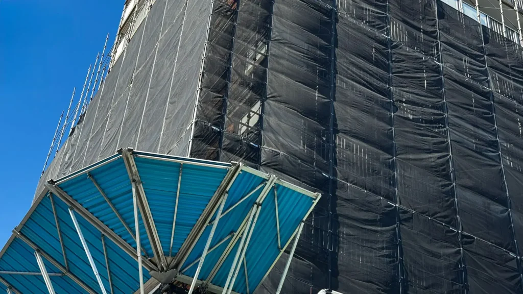
Sheeting, Netting and Wind: The Condition That Changes Everything
If you remember only one warning from this article, remember this:
Never add sheeting and assume the original tie layout is automatically still adequate.
Sheeting changes how wind interacts with the scaffold.
An open scaffold allows much of the air to pass through.
A sheeted scaffold creates a much larger temporary wind surface.
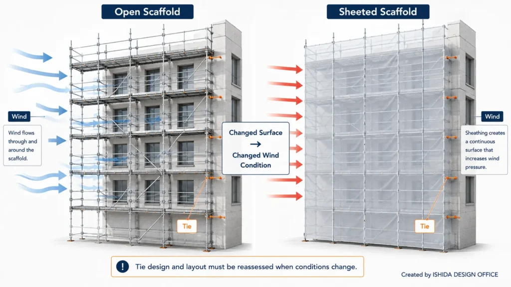
HSE specifically warns that sheeting increases the effect of wind on scaffolding and increases the load transferred to the building.
Safe Work Australia similarly says more ties may be required where scaffolds are sheeted or netted because of increased wind loading.
Sheeting can increase:
- lateral scaffold loads;
- tie forces;
- anchor forces;
- load transferred to the building;
- overturning demand;
- demand at upper levels;
- demand at corners and exposed zones.
So the correct question is not:
“How many ties do we have?”
It is:
“What force is this tie system expected to transfer in the scaffold’s actual condition?”
That is a very different way of thinking.
And a safer one.
How I Review a Scaffold Tie Layout
When I receive a scaffold elevation, I do not begin by counting every tie.
I first look at the overall pattern.
That gives me a much better understanding of what the designer is trying to achieve.
Step 1 — Zoom Out
Before checking individual ties, look at:
- overall height;
- overall length;
- returns;
- corners;
- setbacks;
- openings;
- stair towers;
- loading bays;
- bridges;
- cantilevers;
- sheeted areas.
I want to understand the scaffold before I judge the tie grid.
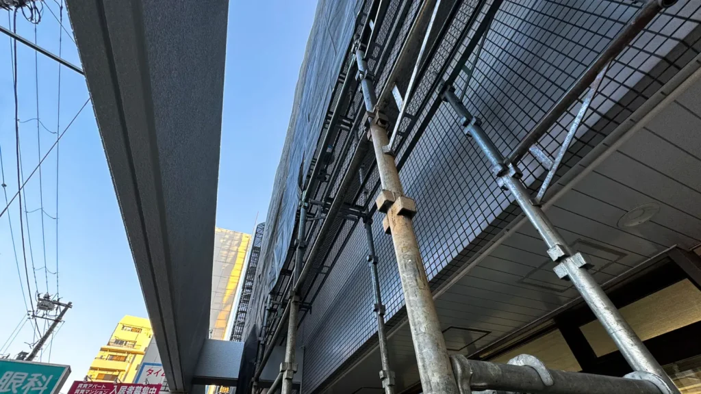
Step 2 — Identify the Basic Pattern
Ask:
- Is it regular?
- Staggered?
- Manufacturer-based?
- Denser at critical areas?
- Interrupted by openings?
A non-uniform arrangement is not automatically wrong.
But significant changes in the pattern should have a reason.
Step 3 — Check Both Ends
Do not concentrate only on the middle of a long elevation.
The end of the scaffold cannot rely on continuation into another bay.
OSHA’s requirement for restraint at each end is a useful reminder of this principle.
I always review end bays separately.
Step 4 — Check the Top
Look at the distance between the highest effective tie and the top of the scaffold.
This becomes especially important when:
- extra lifts are added;
- the scaffold extends beyond the roof;
- temporary sheeting is added;
- demolition changes the supporting building height.
HSE specifically warns that the projection of sheeted scaffolds above the highest effective ties needs to be controlled during demolition.
Step 5 — Check Openings
Windows, doors, balconies and entrances often break the ideal grid.
Whenever I see a large gap, I ask:
Where did the missing tie go?
If the answer is:
“We just skipped it,”
the review is not complete.
Possible solutions may include:
- an adjacent replacement;
- an alternative anchor;
- relocation;
- a special restraint detail.
Step 6 — Check Non-Standard Features
Look carefully at:
- loading bays;
- hoists;
- rubbish chutes;
- bridges;
- lattice beams;
- cantilevers;
- stair towers;
- temporary roofs;
- large signs;
- projecting platforms.
These can change scaffold behaviour and may require special design consideration.
Step 7 — Compare Elevation, Plan and Section
A tie can look perfectly possible in elevation and still be impossible to install.
The plan may reveal:
- a balcony;
- a setback;
- a canopy;
- a property boundary.
The section may reveal:
- deep cladding;
- insulation;
- a projecting slab;
- façade clearance;
- an unsuitable anchor zone.
This is why I prefer to review:
Plan + Elevation + Section + Detail
together.
The scaffold is three-dimensional.
The review should be too.
Installation: The Tie System Must Work During Erection Too
A scaffold can be adequate when complete but unstable while it is being erected.
That is why tie planning needs to consider sequence.
HSE says ties should be installed as the scaffold is erected.
A sensible general sequence is:
- Confirm the approved scaffold information.
- Confirm the tie layout.
- Confirm the anchor locations.
- Verify substrate and connection details.
- Erect progressively.
- Install restraints at the required stages.
- Do not allow erection to run significantly ahead of the stability arrangement.
- Inspect before handover.
- Record significant changes.
What I Would Not Recommend
Do not:
- erect the complete scaffold and “add ties later”;
- omit a tie because the anchor position is inconvenient;
- substitute an improvised tube for a designed restraint;
- drill into an unknown substrate;
- install sheeting without reviewing design assumptions;
- remove ties without an approved stability strategy.
What Happens When a Tie Has to Be Removed?
This is one of the most realistic scaffold problems.
A tie is exactly where somebody needs to:
- paint;
- install cladding;
- waterproof;
- apply sealant;
- clean;
- repair the wall.
So the tie becomes inconvenient.
HSE’s principle is very clear: if a tie has to be removed to allow work to proceed, equivalent restraint should be provided nearby to maintain stability.
The sequence should not be:
Remove tie → Finish façade → Remember later
A better sequence is:
- Identify the conflict.
- Check the approved design.
- Determine the alternative restraint.
- Install the replacement where required.
- Verify the condition.
- Remove the original tie.
- Complete the façade work.
- Restore or formally revise the arrangement.
- Inspect.
- Record the change.
It takes more planning.
But it usually costs less than discovering later that several lifts have been operating with an altered restraint system.
Inspection and Records
A scaffold is not finished when erection is complete. Ties have to remain effective during the life of the scaffold.
OSHA requires a competent person to inspect scaffolds and scaffold components for visible defects before each work shift and after events that could affect structural integrity.
HSE also requires scaffold inspection at relevant stages and after events such as substantial alteration or adverse weather.
Safe Work Australia specifically warns that finishing trades may loosen, move or remove ties to gain access to walls and openings.
That is a very realistic warning.
I Would Recheck Ties After:
- strong wind;
- severe weather;
- impact;
- partial dismantling;
- scaffold alteration;
- tie relocation;
- façade work;
- sheeting installation;
- sheeting removal;
- loading-bay alteration;
- hoist installation;
- rubbish-chute installation.
Useful Records
Depending on the project:
- inspection checklist;
- marked-up elevation;
- tie schedule;
- anchor register;
- anchor installation records;
- testing records where required;
- photographs;
- drawing revision;
- method-statement revision;
- handover record.
The objective is not paperwork for paperwork’s sake.
It is to answer one question:
Does the scaffold on site still match the scaffold everyone believes was approved?
Common Scaffold Tie Mistakes
Most tie failures in planning are not caused by an impossibly complicated engineering problem.
They often begin with small assumptions.
1. Using One Spacing Number Everywhere
Problem:
A maximum regulatory value is treated as a universal design grid.
Better approach:
Check configuration, loads, manufacturer guidance and site conditions.
2. Copying a Tie Layout From Another Project
Two buildings that look similar may have different:
- height;
- width;
- terrain;
- wind exposure;
- sheeting;
- substrate.
Better approach:
Never copy a pattern without checking its assumptions.
3. Adding Sheeting Without Reviewing the Ties
Problem:
The scaffold changes but the tie drawing does not.
Better approach:
Review wind, tie and anchor demand before containment is installed.
4. Removing Ties for Façade Work
Problem:
A tie is inconvenient, so it disappears.
Better approach:
Plan equivalent restraint before removal.
5. Ignoring the Anchor Substrate
Problem:
The scaffold connection looks correct, but the building connection is questionable.
Better approach:
Verify the anchor and the actual substrate.
6. Leaving Too Much Scaffold Above the Highest Tie
Problem:
Extra scaffold is added at the top without reconsidering stability.
Better approach:
Check the top-restraint condition against the approved design.
7. Forgetting the Ends
Problem:
The middle of the elevation looks excellent, but the end bays are poorly restrained.
Better approach:
Review both ends separately.
8. Treating Every Tie as Identical
Corner zones, openings and non-standard bays may create different demands.
Better approach:
Think about the load path—not only the number of dots.
9. Improvising a Connection
Problem:
The planned connection cannot be installed, so somebody invents another one on site.
Better approach:
Return the problem to the responsible competent designer or technical person.
10. Letting the Drawing and Site Drift Apart
This is the problem I take most seriously.
A drawing may be correct on Monday.
By Friday:
- two ties have moved;
- sheeting has been added;
- a loading bay has changed;
- one opening is larger;
- a hoist has appeared.
You may now have a different structure.
The safest question is:
Does the installed scaffold still match the approved assumptions?
Japanese Practice Note
Japanese façade-scaffold work often has to fit into very restricted spaces. Neighbouring properties may be close, pedestrian routes may run immediately beside the scaffold, and protective mesh or sheeting is common during renovation work.
From more than 30 years of scaffold drawing, planning and temporary-works experience, one habit I consider particularly valuable is checking the proposed tie pattern against the actual façade before treating the drawing as complete.
A regular CAD grid may look clean, but a real building contains windows, balconies, waterproofing layers, tile, cladding, weak substrates, canopies and locations where drilling is restricted.
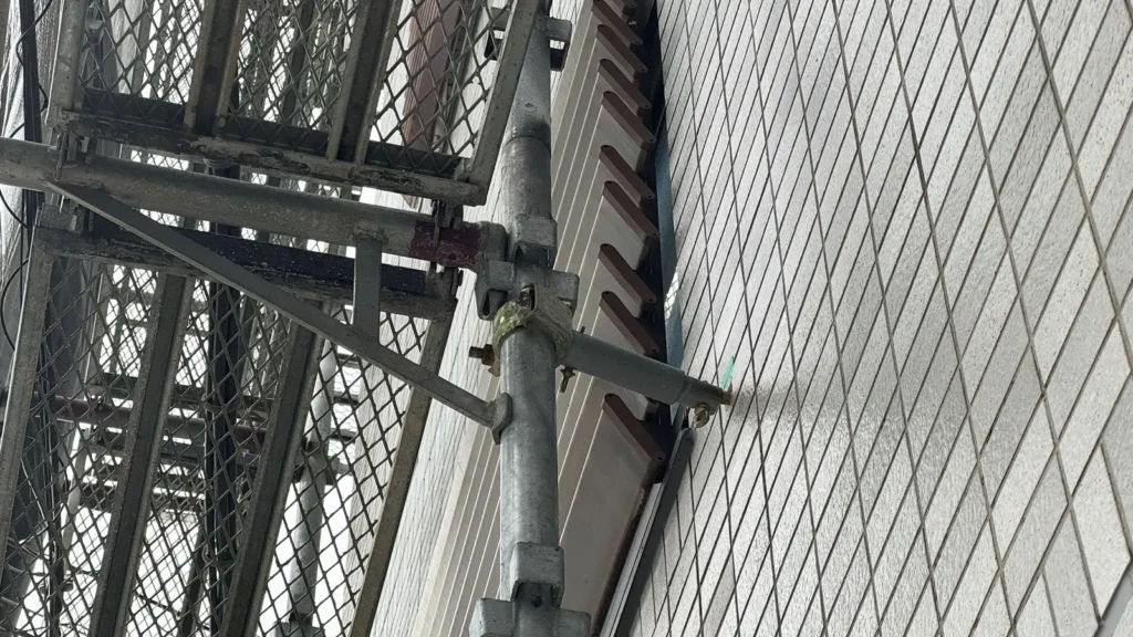
Japanese regulations provide wall-tie spacing requirements for specified scaffold categories, but in practice I do not believe the supervisor should stop at the regulatory number. I also want to understand:
- sheeting;
- wind exposure;
- anchor substrate;
- openings;
- upper lifts;
- corners;
- whether the detail can actually be constructed.
That approach is useful outside Japan too.
A technically neat tie grid is not enough if the scaffold cannot be built as drawn.
Requirements vary by country, jurisdiction and project. Always confirm local regulations, project requirements and the manufacturer’s current instructions before finalising tie type, spacing or layout.
The practical philosophy reflected here is also consistent with ISHIDA DESIGN OFFICE’s Japanese guidance on wedge-lock scaffold wall ties, which emphasises that spacing, wind effects, the actual wall connection and structural verification need to be considered together rather than in isolation.
Practical Scaffold Tie Checklist
This is the checklist I would want a supervisor to be able to use tomorrow morning.
Design and Documentation
- Applicable regulation or manufacturer configuration identified
- Tie horizontal spacing shown
- Tie vertical spacing shown
- Tie duty or design assumptions identified where necessary
- Scaffold height confirmed
- Scaffold width confirmed
- Top restraint reviewed
- End restraints reviewed
- Openings reviewed
- Corners reviewed
- Loading bays reviewed
- Cantilevers reviewed
- Stair towers reviewed
- Hoists and chutes reviewed
- Sheeting or netting included in the design condition
Connections
- Tie type identified
- Anchor type identified
- Substrate identified
- Anchor capacity verified where required
- Edge distance acceptable
- Installation detail available
- Testing requirement confirmed
- Connection can actually be built as drawn
Site Condition
- Installed ties match the approved layout
- No missing ties
- No unauthorised relocations
- No loose couplers
- No damaged members
- No questionable anchors
- No unapproved sheeting changes
- No newly added loads
- No excessive projection above the highest tie
Change Control
- Removed ties have approved alternative restraint
- Alterations recorded
- Drawings revised where necessary
- Inspection completed after significant changes
- Site team understands ties must not be removed without authorisation
The checklist is deliberately asking more than:
“Is there a tie?”
The real question is:
“Is this still the tie system that was designed?”
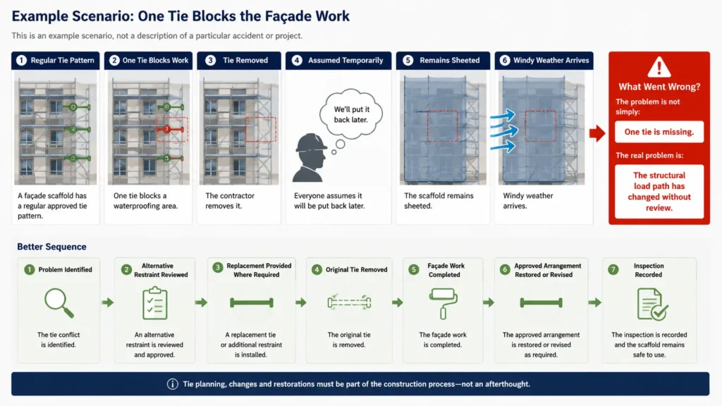
Example Scenario: One Tie Blocks the Façade Work
The following is an example scenario, not a description of a particular accident or project.
A façade scaffold has a regular approved tie pattern.
One tie blocks a waterproofing area.
The contractor removes it.
Everyone assumes it will be put back later.
The scaffold remains sheeted.
Windy weather arrives.
What Went Wrong?
The problem is not simply:
One tie is missing.
The real problem is:
The structural load path has changed without review.
Better Sequence
Problem identified
↓
Alternative restraint reviewed
↓
Replacement provided where required
↓
Original tie removed
↓
Façade work completed
↓
Approved arrangement restored or revised
↓
Inspection recorded
This is why I believe tie planning belongs in the construction sequence.
Not only on the scaffold elevation.
A Good Tie Layout Is Also a Coordination Drawing
A good scaffold drawing does more than show geometry.
It helps different people communicate.
A well-prepared tie layout tells:
- the designer where lateral loads are transferred;
- the scaffolder where restraint is required;
- the supervisor what needs to be checked;
- the façade contractor which locations cannot simply disappear;
- the safety team which changes may affect structural stability.
That is valuable.
If a tie clashes with:
- a façade panel;
- waterproofing;
- an entrance;
- a window;
- a canopy;
I would rather solve that problem on the drawing.
Trying to solve it with an improvised decision several storeys above ground is normally slower, more expensive and more stressful.
Cost and Planning Impact
I would not publish one universal “price per scaffold tie.”
Costs vary too much between countries, projects and anchor systems.
Instead, I prefer to think about the cost components.
| Cost Element | Main Variables |
|---|---|
| Tie components | Type, quantity, system |
| Anchors | Product, capacity, substrate |
| Labour | Access, drilling difficulty |
| Testing | Anchor testing requirements |
| Engineering | Standard vs bespoke design |
| Rework | Incorrect or relocated ties |
| Façade coordination | Removal / replacement |
| Sheeting | Increased design demand |
| Programme | Delays caused by unresolved locations |
Poor tie planning can create hidden costs through:
- repeated drilling;
- damaged finishes;
- drawing revisions;
- scaffold alterations;
- engineer revisits;
- additional inspection;
- delays to façade trades.
This is why I prefer solving difficult tie locations during design review.
A little planning can save a surprising amount of site time.
Manufacturer Tie Patterns: Use Them in Context
For proprietary system scaffolds, manufacturer documentation matters.
Do not assume that a tie layout for one system can be transferred directly to another.
Manufacturer documentation may define:
- standard configurations;
- maximum heights;
- tie patterns;
- tie duty;
- bracing arrangements;
- loading classes;
- restrictions on sheeting;
- additional edge-bay requirements.
The important principle is:
Manufacturer data belongs to the configuration and conditions for which it was published.
A dimension taken from one manual is not automatically a universal scaffold rule.
When May Bespoke Design Be Needed?
The exact legal trigger varies between jurisdictions.
But the practical principle is widely useful:
When the scaffold moves outside a recognised or manufacturer-approved configuration, assumptions should give way to verification.
HSE says scaffolds outside recognised standard configurations or relevant manufacturer guidance should be subject to bespoke calculation by a competent person.
Examples may include:
- unusual height;
- extensive sheeting;
- temporary roofs;
- large loading bays;
- cantilevered platforms;
- bridges;
- unusual foundations;
- restricted tie locations;
- major façade offsets;
- unusual wind exposure;
- signs or hoardings;
- unusual anchor substrates.
This work must be carried out under appropriate competent supervision and in accordance with local requirements.
The Four Questions I Would Ask Tomorrow Morning
If you have only five minutes to review a scaffold, start with these four questions.
1. Does the Installed Tie Pattern Match the Drawing?
If not:
Why not?
Do not accept “because it was difficult” as the end of the discussion.
2. Has Anything Changed Since the Design?
Especially:
- sheeting;
- loading bays;
- height;
- hoists;
- cantilevers;
- access;
- tie removals.
Small site changes can have structural consequences.
3. What Are the Ties Actually Connected To?
Do not stop at the scaffold side.
Look all the way to the receiving structure.
4. Can I Explain the Load Path?
You do not need to perform the full structural calculation on the spot.
But you should understand:
Scaffold → Tie → Anchor → Structure
If that chain is unclear, ask.
That question alone can reveal a surprising number of problems.
Related Topics
If you are reviewing ties, the next logical step is to review the whole scaffold drawing rather than the elevation alone.
Recommended related articles:
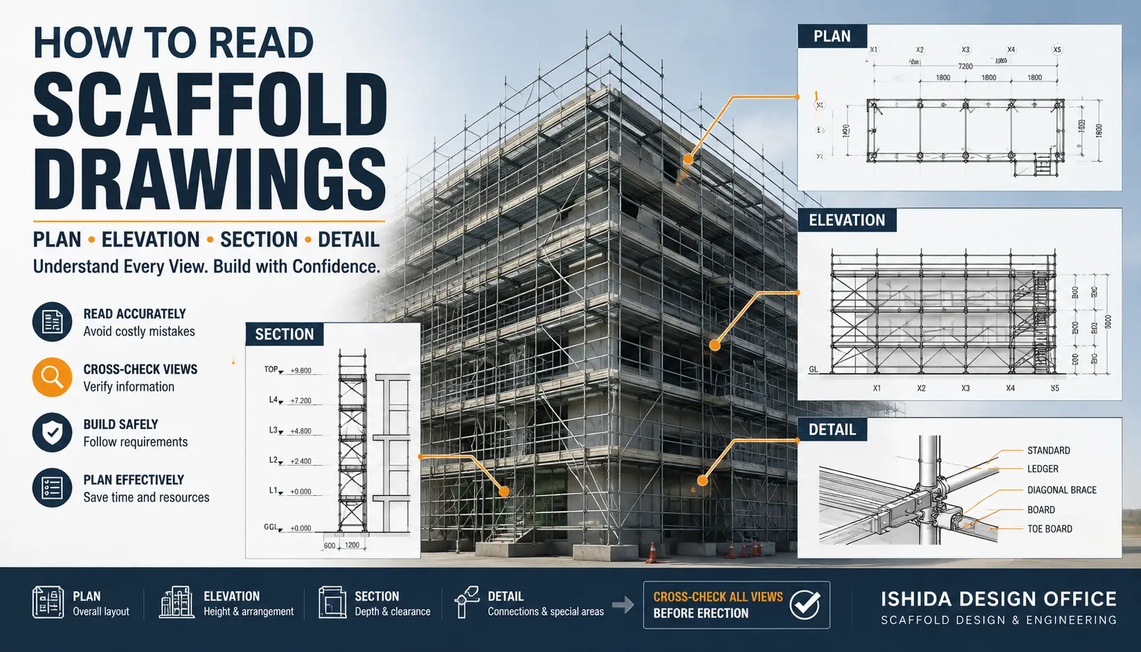
How to Read Scaffold Drawings: Plan, Elevation, Section & Details
Use this when you need to understand how tie positions interact with the building geometry.
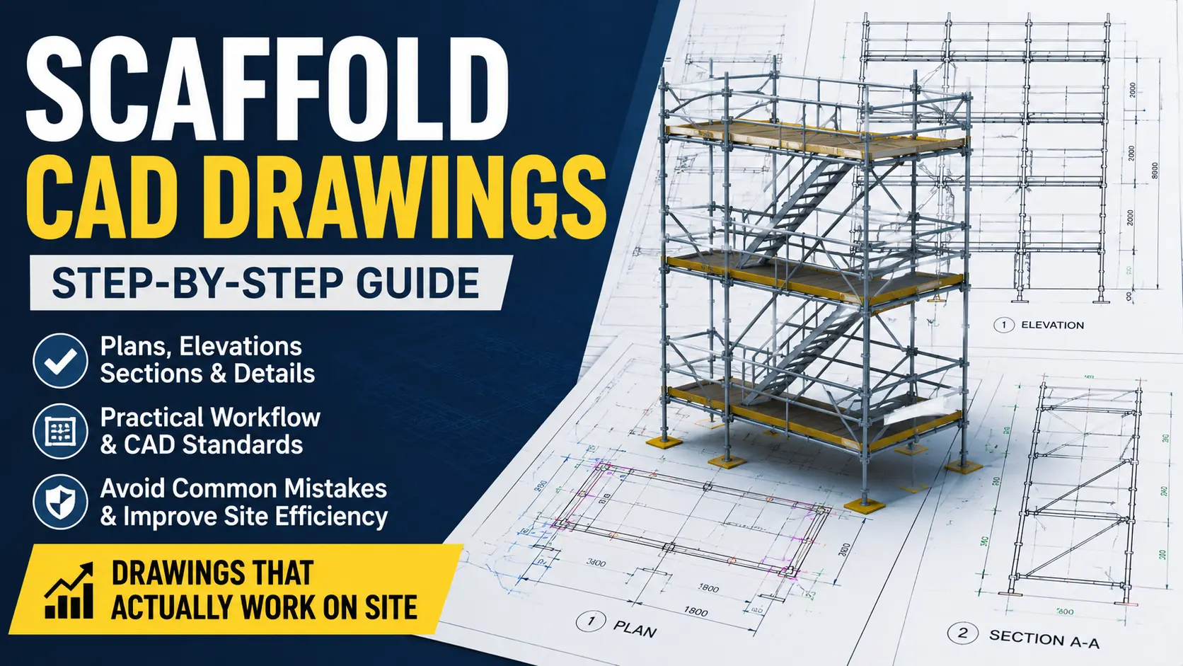
How to Create Scaffold CAD Drawings That Actually Work on Site
Useful when tie locations, openings, canopies and non-standard details need to be coordinated before erection.
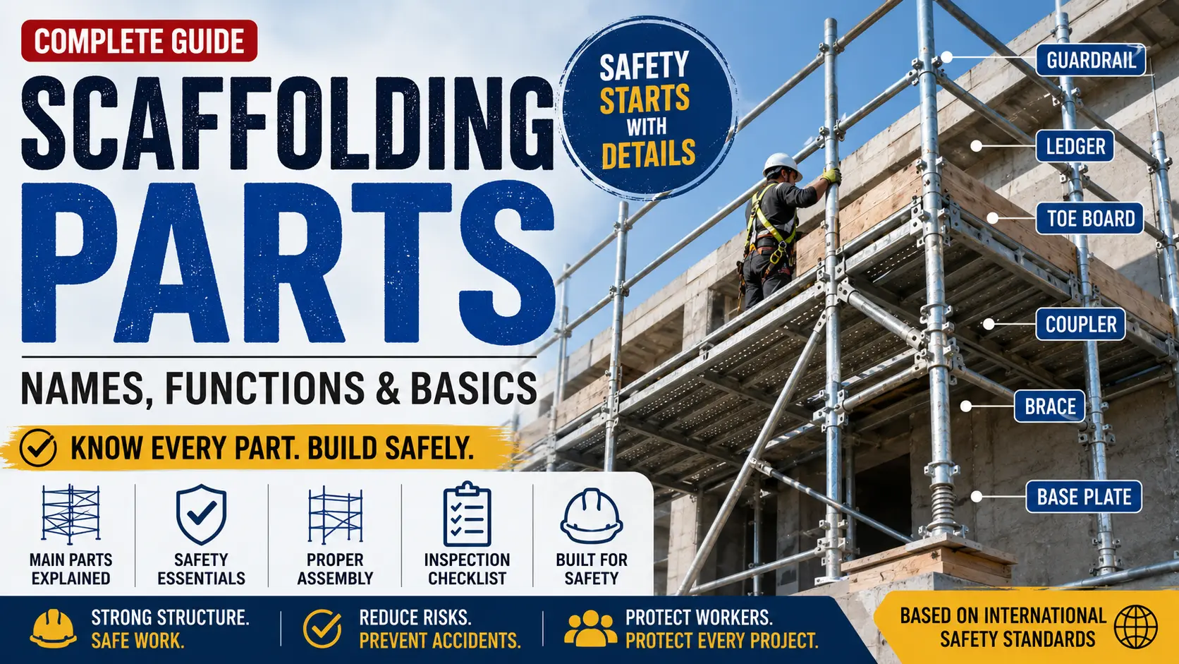
Scaffolding Parts Explained: Names, Sizes & Functions
Useful when you need a broader understanding of standards, ledgers, braces, ties and other components.
And remember:
Calculation tells you why.
Drawing tells you where.
Inspection tells you whether it was actually built.
Key Takeaways
1. A Scaffold Tie Is Part of a Load Path
Do not check only the tube.
Check:
Scaffold → Tie → Anchor → Structure
2. There Is No Universal Tie Spacing
OSHA, HSE, Australian jurisdictions, Japanese regulations and manufacturer systems use different frameworks.
3. Maximum Spacing Is Not Automatically Design Spacing
Openings, loading bays, sheeting and unusual geometry may require a different arrangement.
4. Sheeting Can Change the Structural Condition
Never assume that an open-scaffold tie layout remains adequate after containment is added.
5. Anchor Capacity Matters
A good scaffold-side connection cannot compensate for an unsuitable building connection.
6. Missing Ties Are Not Small Site Adjustments
A removed or relocated tie can change the structural load path.
7. The Drawing Must Match the Real Building
The best tie grid is one that can actually be installed safely.
Conclusion
Scaffold ties are easy to underestimate because they occupy so little space on a drawing.
But they form one of the key connections between the temporary scaffold and the permanent structure that provides its lateral restraint.
After more than 30 years working with scaffold planning and drawings, I still believe one of the best habits a supervisor can develop is very simple:
When you see a tie on a drawing, do not just ask where it is. Ask what it is doing.
That one question changes the review.
You begin to notice:
- missing load paths;
- unrealistic anchor positions;
- excessive spacing;
- sheeting changes;
- weak substrates;
- site alterations;
- coordination problems.
And those are exactly the details that can create expensive rework later.
I hope this guide helps you make your next scaffold safer, easier to inspect, less expensive to correct and easier to explain to everyone involved.
If this kind of practical scaffold explanation is useful to you, I hope you will return to ISHIDA DESIGN OFFICE and Scaffold Design Hub when your next difficult site question appears.
Keep checking the small details.
They often prevent the big problems.
FAQ
How far apart should scaffold ties be?
There is no one spacing that applies to every scaffold worldwide.
In the United States, OSHA 29 CFR 1926.451(c)(1) provides specific supported-scaffold restraint requirements when the height-to-base-width ratio exceeds 4:1. Other jurisdictions and manufacturer systems use different requirements. Always check the applicable regulation, manufacturer guidance and project-specific design.
Does scaffold sheeting require more ties?
It may.
Sheeting and netting can increase wind load on the scaffold and therefore increase the forces transferred through ties and anchors. HSE and Safe Work Australia both specifically warn about this effect.
Can a scaffold tie be temporarily removed?
Only while the required stability is maintained.
HSE advises that where a tie is removed to allow work to proceed, equivalent restraint should be provided nearby. The approved design and local requirements should govern the procedure.
Are scaffold ties always fixed into concrete?
No.
Depending on the building and design, ties may connect through openings, structural members, suitable masonry or concrete anchors, or another approved restraint arrangement.
The receiving structure must be capable of accepting the relevant design action.
Can I use OSHA’s 30 ft horizontal interval on every scaffold?
No.
OSHA’s 30 ft figure is part of a specific supported-scaffold regulation. It should not be treated as a universal international tie-grid dimension.
Manufacturer instructions, scaffold width, height, loading and local rules still apply.
Are system-scaffold ties spaced the same as tube-and-coupler scaffold ties?
Not necessarily.
Proprietary systems may have configuration-specific tie patterns. HSE specifically says proprietary system scaffolds should be erected and tied according to the manufacturer’s instructions.
Who should decide a non-standard scaffold tie layout?
The exact legal requirement varies.
Where a scaffold falls outside recognised standard configurations or applicable manufacturer guidance, a competent or appropriately qualified person may need to design or verify the arrangement.
Official References
United States
Occupational Safety and Health Administration — 29 CFR 1926.451, General Requirements for Scaffolds
Relevant to:
- supported-scaffold stability;
- 4:1 height-to-base-width criterion;
- guy, tie and brace placement;
- end and horizontal restraint intervals;
- eccentric loading;
- competent-person inspection.
United Kingdom
Health and Safety Executive — Scaffolds
Relevant to:
- ties;
- rakers;
- proprietary-system instructions;
- erection sequence;
- tie removal;
- bespoke scaffold design.
Health and Safety Executive — Structural Stability During Alteration, Demolition and Dismantling
Relevant to:
- scaffold lateral stability;
- wind;
- sheeting;
- projection above the highest effective ties.
Australia
Safe Work Australia — General Guide for Scaffolds and Scaffolding Work
Relevant to:
- tie spacing;
- manufacturer/designer instructions;
- additional ties with sheeting;
- loading platforms;
- lifting appliances;
- scaffold anchors;
- unauthorised tie alteration.
Safe Work Australia — Scaffolding
Provides current national guidance and directs users to the appropriate state or territory regulator.
Japan
Relevant to:
- wall ties;
- Article 570;
- specified spacing for applicable steel-tube and frame-scaffold categories;
- wedge-lock scaffold considerations.
ISHIDA DESIGN OFFICE Technical Background
Wedge Scaffold Wall Tie Spacing — Safety Standards and Practical Pitch
Used as practical background for:
- wall-tie spacing;
- wind effects;
- inspection;
- site coordination;
- the difference between a nominal rule and practical layout.
Structural Calculation for Wedge Scaffold Wall Ties
Used as practical background for:
- structural verification;
- wind loading;
- tie design;
- the relationship between drawings and calculations.
Safety Disclaimer
This article is intended for general educational purposes.
It is not a substitute for project-specific scaffold design, engineering calculations, competent-person assessment, approved method statements, manufacturer documentation or applicable legal requirements.
Requirements vary by country, jurisdiction, scaffold system and project.
Always follow local laws, project specifications, approved design information and the scaffold manufacturer’s current instructions.
Where the correct requirement is uncertain, consult the official guidance and an appropriately competent or qualified person.
Last Verified: August 2026
All external references and official guidance cited in this article were checked for accessibility at the time of writing.
Scaffold requirements, regulations, guidance and manufacturer documentation may vary by country, jurisdiction, scaffold system and project, and may change over time. Readers should confirm the latest requirements through the relevant authority, local regulator, project specifications, engineering information and the current technical documentation for the scaffold system being used.
About the Author
ISHIDA DESIGN OFFICE brings more than 30 years of practical experience in Japan, specializing in scaffolding design, temporary works planning, CAD drafting, quantity estimation, and construction support.
Drawing on experience from residential, commercial, and industrial projects, he shares practical insights that emphasize not only sound engineering design but also buildability, safety, and real-world jobsite application.
At Scaffold Design Hub, he combines practical experience from Japan with official guidance and technical resources from government agencies, manufacturers, and industry organizations around the world to provide reliable, practical information for construction professionals.
To learn more, visit the About page. For questions or project inquiries, please use the Contact page.