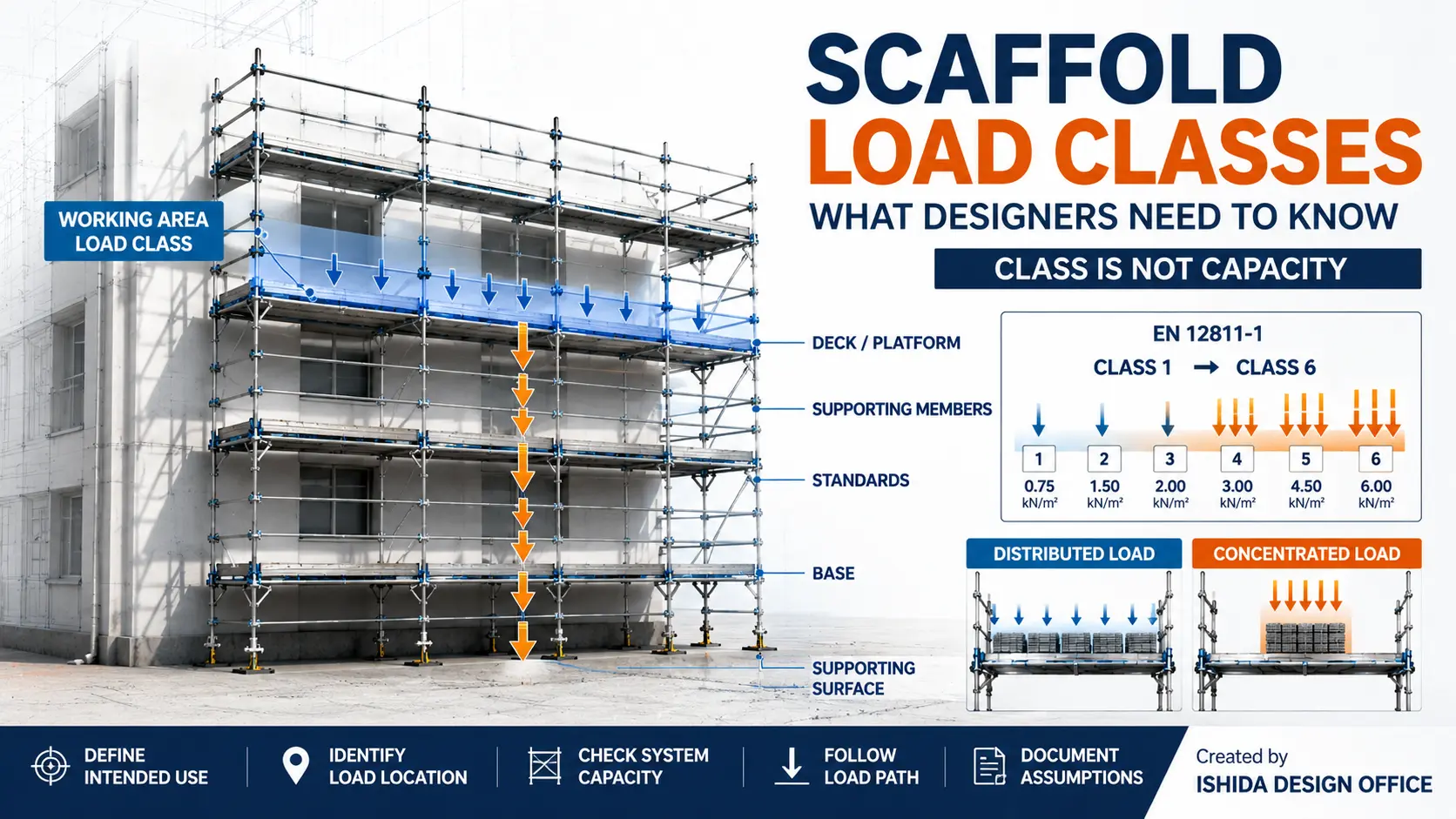
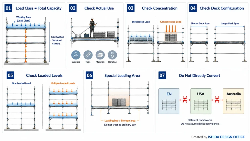
A scaffold load class defines a loading requirement for the working area. It does not, by itself, tell you the total capacity of the entire scaffold.
That distinction is one of the most important points for designers.
A scaffold may have a specified working-area load class, but the designer still needs to consider how the scaffold will actually be used, where workers and materials will be located, whether loads may become concentrated, how many levels may be loaded, what scaffold components are being used, and how those loads are transferred through the structure.
Under EN 12811-1, working areas are classified into six load classes. Other jurisdictions use different systems. OSHA requirements in the United States, for example, are expressed differently and should not be treated as a direct equivalent of the EN classification system.
This guide explains what scaffold load classes mean, what they do not mean, and what designers should check before translating a load requirement into a scaffold design.
KEY IDEA
Load class is not total scaffold capacity. It is one part of the loading basis that must be considered together with actual use, component capacity, load paths and support conditions.
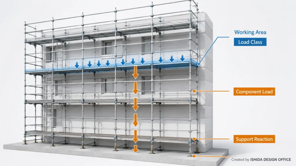
What Is a Scaffold Load Class?
A scaffold load class is a way of defining the design loading for a working area under a particular standard or scaffold system.
For EN-based scaffolding, EN 12811-1 provides six working-area load classes. Manufacturer technical documentation for EN-compliant systems commonly identifies which deck lengths and configurations are suitable for particular classes. For example, PERI’s official technical documentation lists deck suitability against Classes 1–6 rather than assuming that every deck length has the same capacity.
This immediately leads to an important design principle:
DESIGN PRINCIPLE
Specifying a load class is only the beginning of the load review.
Load Class Is a Design Condition, Not a Complete Scaffold Capacity
Several terms can sound similar but describe different things:
- working-area load class
- uniformly distributed load
- concentrated load
- load on an individual deck or component
- maximum intended load
- load transmitted into standards and other structural members
- reaction at the scaffold base
- the rated or allowable capacity of a particular scaffold component or system
They should not be treated as interchangeable.
In scaffold design work, I consider it important not to judge the loading condition from a single imposed-load figure alone. The intended use of the scaffold has to be understood first: whether the platform will primarily carry workers, whether tools and materials will be placed on it, whether material handling will occur, and whether several working levels could be used at the same time.
That distinction becomes increasingly important as the scaffold becomes larger or its use becomes more complex.
Why the Intended Use Matters
Consider two scaffolds with identical geometry.
They could have:
- the same height
- the same bay lengths
- the same platform width
- the same number of lifts
- the same external appearance
But if one is used for relatively light work while the other is used for work involving substantial material storage, the design loading may be very different.
CORE POINT
Same geometry does not automatically mean same loading condition.
That is why the designer needs to understand the intended use rather than selecting a load class from appearance alone.
EN 12811-1 Scaffold Load Classes 1–6
EN 12811-1 classifies working areas into six load classes.
Manufacturer documentation published for EN 12811 systems reproduces the following nominal uniformly distributed loads.
| Load Class | Uniformly Distributed Load |
|---|---|
| Class 1 | 0.75 kN/m² |
| Class 2 | 1.50 kN/m² |
| Class 3 | 2.00 kN/m² |
| Class 4 | 3.00 kN/m² |
| Class 5 | 4.50 kN/m² |
| Class 6 | 6.00 kN/m² |
These values are useful, but the table should not be interpreted as:
DO NOT ASSUME
“Choose a number from the table and the scaffold design is complete.” It is not.
The figures describe specified working-area loading conditions within the EN framework. They do not independently establish the allowable capacity of every deck, ledger, standard, base, tie or complete scaffold configuration.
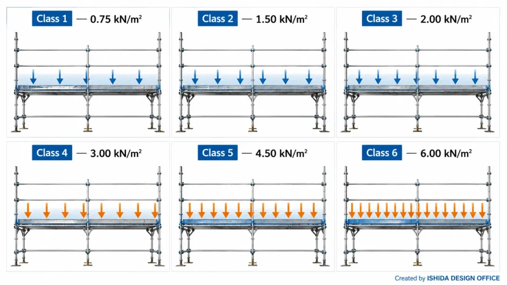
Uniformly Distributed Working-Area Loads
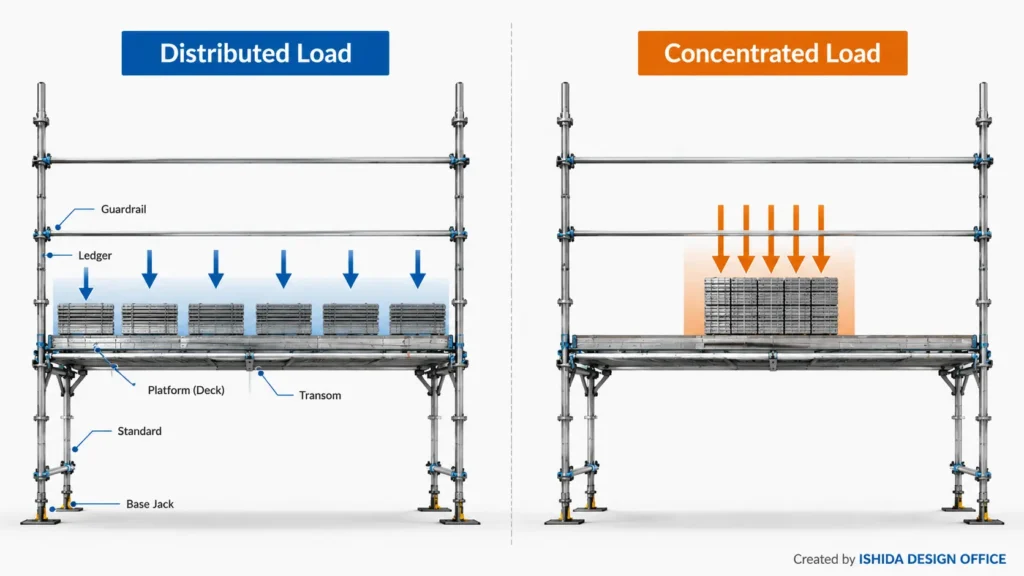
A uniformly distributed load assumes that the load is distributed over the relevant area.
Real construction loading is not always so neat.
Workers move. Tools are placed down. Materials are stacked. Equipment may remain in one location. Packages of material may arrive before being distributed along the working platform.
Therefore, an average load over a whole platform does not describe every possible local loading effect.
Concentrated and Partial-Area Loading
This is why EN 12811-1 does not consider only uniformly distributed loading.
Published manufacturer documentation based on EN 12811 also identifies concentrated-load requirements. For Classes 4–6, partial-area loading is particularly significant.
For example, Hünnebeck’s published EN 12811 loading table identifies partial-area loads of:
- Class 4: 5.00 kN/m²
- Class 5: 7.50 kN/m²
- Class 6: 10.00 kN/m²
in addition to the nominal area loads.
IMPORTANT
The exact application must be checked against the applicable standard and system documentation.
The practical lesson is more important than memorizing another table:
PRACTICAL POINT
Materials on scaffolds do not necessarily create perfectly uniform loading.
Why Classes 4–6 Require Additional Attention
Higher load classes are not simply “the same scaffold with more kilograms added.”
Increasing the required working-area loading can affect whether a particular deck, deck length, bay arrangement or system configuration is suitable.
Manufacturer data illustrates this clearly.
PERI’s published EN 12811 load-class tables show that some deck types and lengths can satisfy higher classes while other combinations cannot. Layher documentation similarly shows load-class limitations changing with deck length.
DESIGN CHECK
Load class must be checked against the actual scaffold system and configuration being used.
Load Class Is Not the Same as Scaffold Load Capacity
This distinction deserves its own section because it prevents a common misunderstanding.
A working-area classification and the structural capacity of the complete scaffold are related, but they are not the same quantity.
Working-Platform Loading
The working platform receives the immediate effects of:
- workers
- tools
- materials
- equipment
- other loads associated with the intended work
The relevant deck or platform components must be suitable for the required loading and configuration.
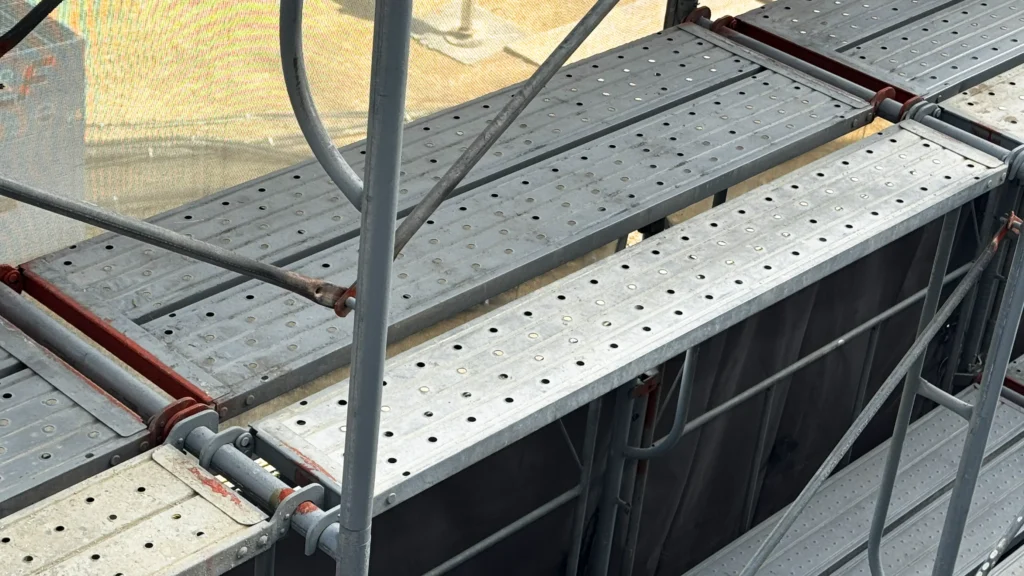
Component Capacity
A scaffold consists of many components performing different structural functions.
The capacity of a platform does not automatically establish the capacity of:
- a ledger
- a transom
- a standard
- a bracket
- a base component
- a tie
- the complete scaffold assembly
Manufacturer instructions and verified system data therefore matter.
A useful example can be seen in PERI’s documentation: different deck types and lengths have different permitted load classes.
Loads Transmitted Through the Scaffold
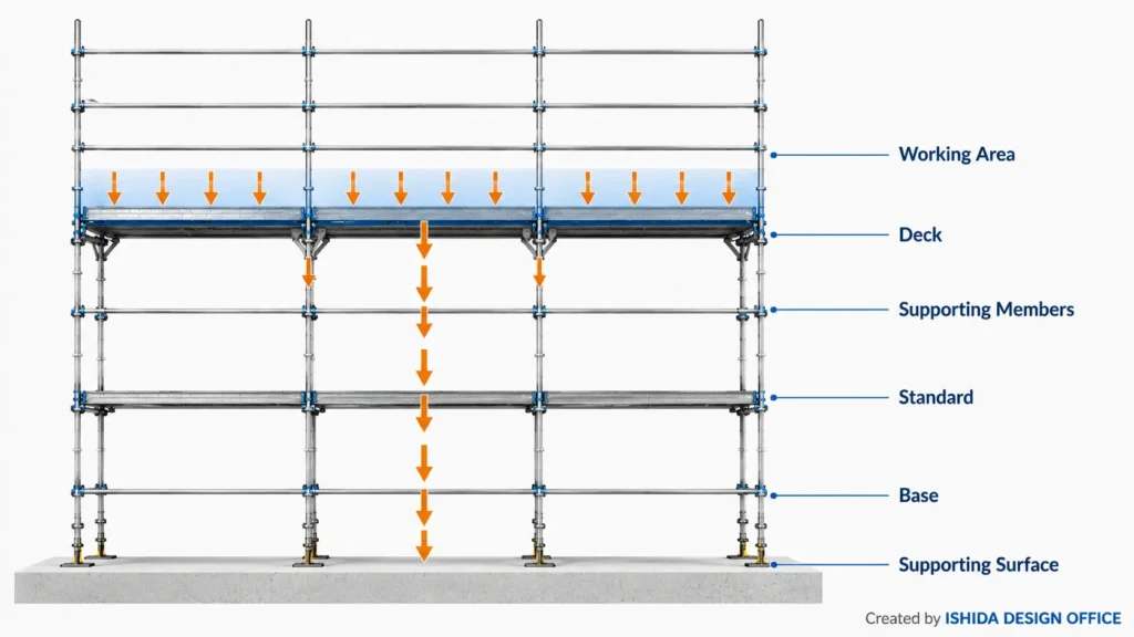
Platform loads do not remain on the platform.
They are transferred through the supporting scaffold structure.
Depending on the system and configuration, vertical loads ultimately pass through supporting members toward the scaffold base and its supporting surface.
For the designer, the relevant question is therefore not only:
“What is the platform load?”
but also:
LOAD-PATH QUESTION
“Where does that load go?”
Maximum Intended Load
OSHA provides a useful comparison because the U.S. regulatory framework approaches scaffold capacity differently.
OSHA defines maximum intended load as the total load of persons, equipment, tools, materials, transmitted loads and other loads reasonably anticipated to be applied to a scaffold or scaffold component at any one time.
Under 29 CFR 1926.451(a)(1), with specified exceptions, each scaffold and scaffold component must support its own weight and at least four times the maximum intended load applied or transmitted to it. OSHA also requires scaffolds to be designed by a qualified person and loaded in accordance with that design.
Importantly, OSHA has clarified that the four-to-one provision applies to the portion of maximum intended load actually applied or transmitted to the particular component—not automatically the total load on the entire scaffold.
This is a good illustration of why terms such as load class, maximum intended load, and component capacity should not be mixed together.
How Should a Designer Select a Scaffold Load Class?
The selection should begin with the intended work—not with a preferred number.
Start With How the Scaffold Will Actually Be Used
Before establishing the design loading, clarify the work activity.
Questions should include:
- What work will be performed?
- How many workers may occupy the relevant area?
- What tools will be used?
- Will materials be stored temporarily on the platform?
- How will materials reach the working level?
- Could materials accumulate in one bay?
- Will equipment be supported by the scaffold?
- Could several levels be working simultaneously?
- Are there designated loading or material-handling areas?
If these conditions are unclear, simply guessing a loading condition can create problems later.
From My Design Work: When Scaffold Use Changes
In my scaffold design work in Japan, I have had to reconsider an initially assumed working-platform load after the intended work changed. Heavy tools were going to be used, and the scaffold was also going to serve as a working stage rather than only the originally anticipated work area.
That change made the original loading assumption unsuitable to accept without further review. I revisited the design loading in light of the revised work activity and the use of the scaffold as a stage.
My lesson from this experience is simple: the design loading must follow the actual work. A scaffold drawing can remain geometrically unchanged while the loads it needs to support change substantially. The tool weights and revised loading values are not provided here, so this is an account of the design decision, not a reusable load specification.
Workers, Tools and Materials
A scaffold used primarily for workers and light tools presents a different loading condition from one carrying substantial construction materials.
This sounds obvious, but the difference is not always obvious on a drawing.
A general arrangement may show the scaffold geometry while saying relatively little about how a contractor intends to use individual platforms.
That information needs to be coordinated.
Material Storage and Concentrated Loading
Material weight is only part of the issue.
The designer should also consider where the material can be placed.
Ten units distributed along a working area do not necessarily produce the same structural effect as the same units stacked together in one location.
This is one reason why concentrated and partial-area loading provisions matter.
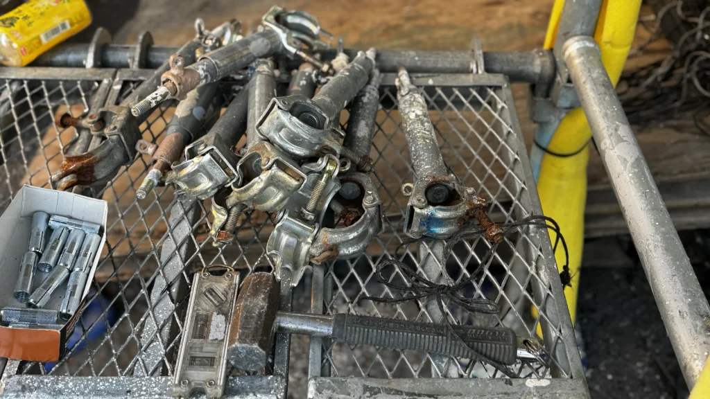
Loading and Material-Handling Areas
Loading bays, hoisting interfaces and designated material-storage areas should not automatically be treated as ordinary working platforms.
They may introduce different loading conditions and require separate assessment.
A drawing should make special loading areas clear where they form part of the design rather than leaving the user to assume that every bay has identical capacity.
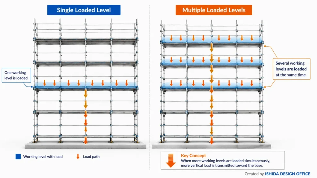
Multiple Working Levels
Another question is frequently more important than the load on a single level:
DESIGN QUESTION
How many levels can be loaded at the same time?
A multi-level scaffold should not automatically be analysed as though every working level carries the same maximum loading simultaneously, nor should the designer automatically assume that only one platform will ever be loaded.
The correct assumption depends on the intended use, applicable design basis, scaffold system and project requirements.
Where simultaneous use is possible, the loading assumptions should be clearly established rather than left implicit.
From My Design Work: Total Vertical Loads and Buckling
When designing scaffolds with more than one working level in use, I have carried out structural checks that consider the vertical loads transmitted to the standards from the relevant loaded levels.
Two points I pay particular attention to are the combined vertical load acting on a standard and the possibility of buckling in the standard or steel scaffold tube. Checking the load on an individual working platform is not enough to establish the adequacy of the supporting members below it.
The actual combination of loaded levels, member lengths, restraint conditions and allowable capacity must be established for the project. The calculation example later in this article illustrates a standard’s axial-load and slenderness check; it should not be assumed to document this same multi-level project.
How Load Class Affects Scaffold Design
Load classification is not isolated from scaffold geometry.
It can influence several parts of the design.
Platform and Deck Selection
Deck capacity should be checked against:
- required load class
- deck type
- deck length
- support arrangement
- manufacturer’s permitted configuration
Do not assume that because one deck in a scaffold system satisfies a particular class, every deck length or type in that system does too.
Official manufacturer tables demonstrate that this can vary.
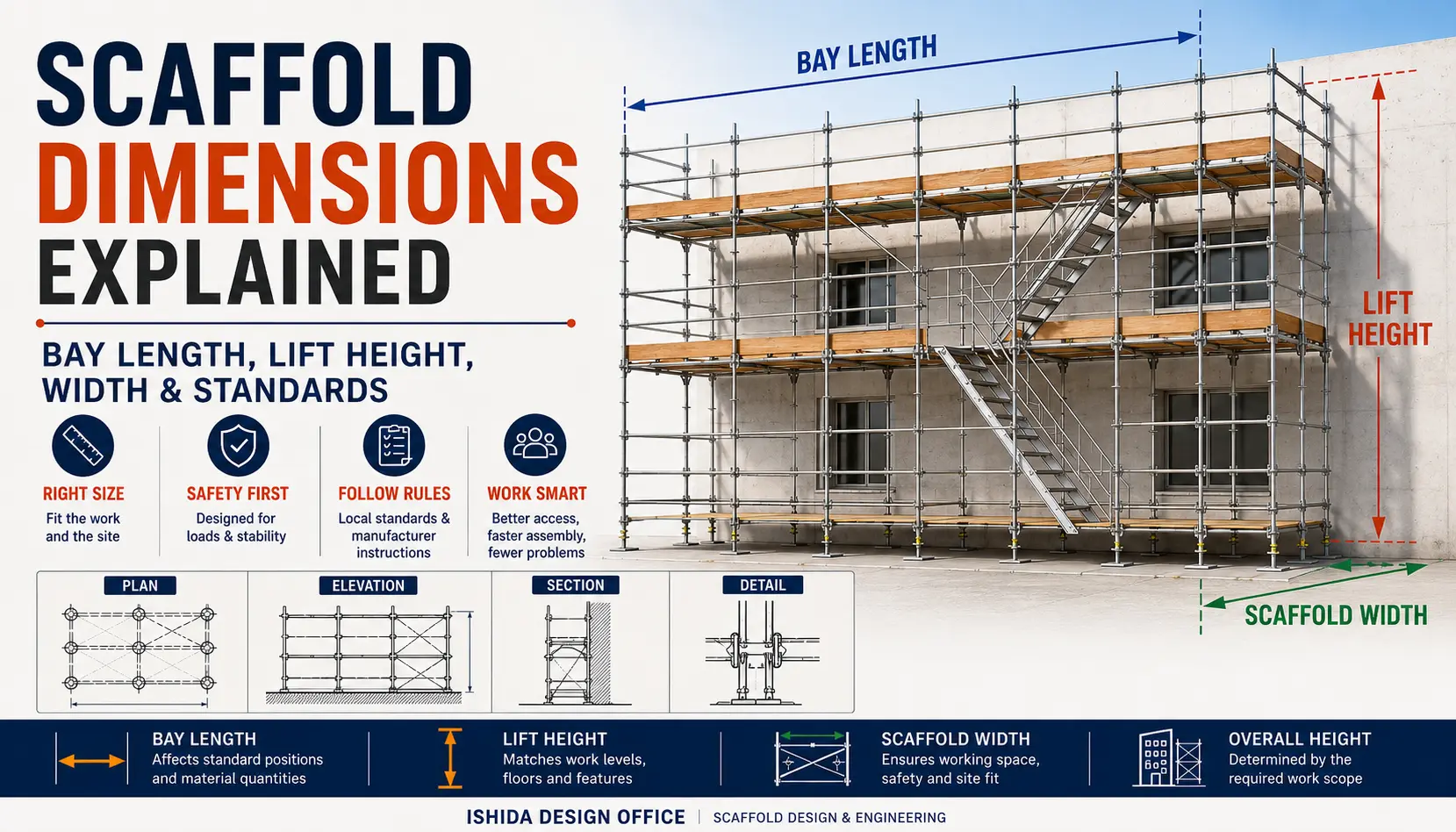
Bay Dimensions and System Configuration
Bay length can affect the structural behaviour and capacity of supporting components.
A configuration acceptable for one loading requirement may not necessarily remain acceptable after the load requirement changes.
This is another reason load class should be established early rather than added to a completed drawing as an afterthought.
For a broader explanation of how bay length, lift height and scaffold width affect scaffold planning, see Scaffold Dimensions Explained: Bay Length, Lift Height, Width & Standards.
Standards and Supporting Members
As loads pass from working platforms through the scaffold, supporting members accumulate load according to the actual structural arrangement.
The designer therefore needs to consider the complete load path rather than reviewing the working platform in isolation.
Base Reactions and Supporting Surfaces
Ultimately, vertical loads must be supported.
Changing working loads or simultaneous loaded levels may change reactions at the base.
The supporting surface therefore forms part of the loading discussion.
A platform being capable of carrying a particular load does not by itself demonstrate that the complete support system and supporting surface are adequate.
Manufacturer Limitations
System scaffolds should be checked against the manufacturer’s technical documentation for the actual:
- component
- length
- configuration
- loading
- system arrangement
- applicable limitations
DO NOT ASSUME
A label such as “Class 4” should never replace that check.
EN Load Classes Are Not a Universal Global System
One of the easiest mistakes in an international scaffold article is to combine different regulatory systems into one apparently universal table.
That should be avoided.
United States — OSHA
OSHA does not simply regulate supported scaffolds by assigning EN 12811 Classes 1–6.
Instead, OSHA requires, among other provisions, that scaffolds and scaffold components be capable of supporting their own weight and at least four times the maximum intended load applied or transmitted to them, subject to the exceptions stated in the regulation. Scaffolds must be designed by a qualified person and loaded in accordance with that design.
OSHA also states that scaffolds and components must not be loaded beyond their maximum intended loads or rated capacities, whichever is less.
Therefore, it would be misleading to present an EN load class as though it automatically establishes OSHA compliance.
Australia — Duty Classifications
Safe Work Australia’s General Guide for Scaffolds and Scaffolding Work describes working platforms as generally rated light, medium or heavy duty and gives example platform-per-bay loading limits:
- Light duty — up to 225 kg per platform per bay
- Medium duty — up to 450 kg per platform per bay
- Heavy duty — up to 675 kg per platform per bay
The guide also states that working-platform duty classifications and dimensions should comply with manufacturer information on loading.
Safe Work Australia provides national WHS guidance but is not the workplace safety regulator. WHS laws are regulated and enforced by the relevant Commonwealth, state or territory authority.
Again, this is a different classification approach.
Why Direct Conversion Can Be Misleading
It may be tempting to write something like:
DO NOT ASSUME
EN Class 3 = Australian Medium Duty = OSHA Medium Duty
That type of conversion should not be assumed.
Different systems may define loads, areas, concentrated loads, component requirements and design criteria differently.
Use the requirements applicable to the actual project jurisdiction.
A Practical Load Review Approach
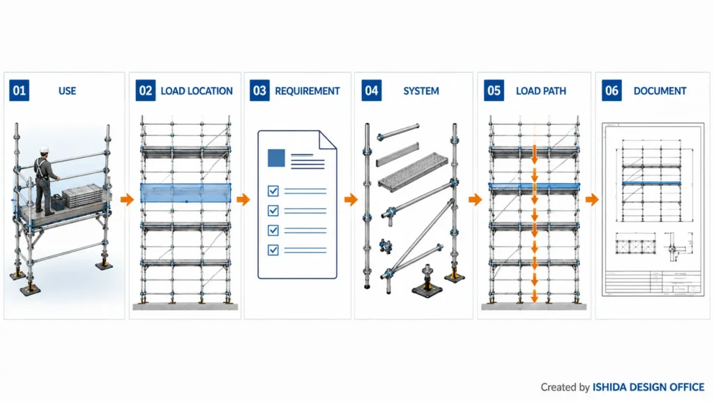
A useful scaffold load review can be organized around six questions.
1. Define the Intended Use
Determine what the scaffold is actually expected to support during the work.
Do not rely solely on a generic project description.
2. Identify Where Loads Will Occur
Separate ordinary working platforms from areas such as:
- material-storage locations
- loading bays
- hoisting interfaces
- equipment locations
- other unusually loaded areas
3. Confirm the Applicable Loading Requirement
Determine which regulation, standard, project specification or design basis applies.
Do not combine classifications from different jurisdictions without verifying their definitions.
4. Check the Scaffold System
Confirm that the selected:
- decks
- supporting members
- bay lengths
- brackets
- standards
- other relevant components
are suitable for the required loading and configuration.
5. Review the Load Path
Follow the load beyond the working platform.
LOAD-PATH CHECK
Platform → supporting members → standards → bases → supporting surface: are all relevant parts accounted for?
6. Document Assumptions
Where loading assumptions affect the design, they should be communicated clearly enough that the scaffold is not used under a materially different loading condition without review.
From an Actual Calculation: Checking a Scaffold Standard
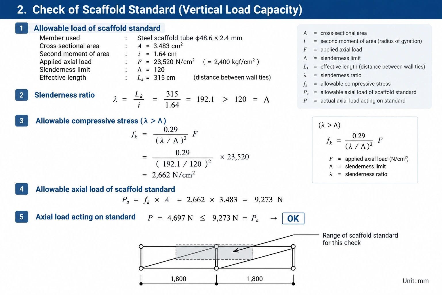
The following English-language graphic is adapted from a portion of an actual scaffold structural calculation provided by ISHIDA DESIGN OFFICE in Japan. It demonstrates a separate check of the vertical load on a steel-tube standard, including member slenderness and an allowable axial-load comparison. It is not a calculation of an EN 12811-1 working-area load class, nor is it proof of compliance with EN, OSHA or Australian requirements.
In the source calculation, the steel tube is specified as 48.6 × 2.4 mm, with an effective length of 315 cm and a radius of gyration of 1.64 cm. The stated slenderness ratio is 192.1. The calculated axial load is 4,697 N, compared with a stated allowable axial load of 9,273 N under the calculation’s own assumptions.
Terminology correction for the graphic: The symbol i means radius of gyration, not second moment of area. The symbol F in the compressive-stress equation is a material-strength parameter expressed in N/cm², not the applied axial load. The applied axial load is P. The source’s design basis, restraint assumptions and calculation method must be independently verified before its numerical conclusion is used on another project.
Example Scenario: Same Scaffold Geometry, Different Loading
ILLUSTRATIVE EXAMPLE
The following is an illustrative example, not an ISHIDA DESIGN OFFICE project.
Imagine a facade scaffold erected around a renovation building.
Its geometry remains unchanged.
Scenario A — Light Work
Initially, the scaffold is intended for workers carrying relatively light tools and materials required for the immediate task.
Material accumulation on the platforms is limited.
Scenario B — Materials Introduced
Later, the work sequence changes.
Larger quantities of facade materials are delivered to the scaffold and workers begin temporarily placing them on working platforms before installation.
The scaffold still looks exactly the same.
But the loading condition may no longer be the same.
The designer may need to review:
- the required working-area loading
- local concentration of materials
- deck capacity
- relevant supporting components
- simultaneous loading of levels
- accumulated vertical loads
- base/support conditions
The Design Lesson
DESIGN LESSON
A change in use can be a change in design loading even when there is no visible change to the scaffold geometry.
This is why the intended use should be communicated and controlled, not merely the dimensions of the scaffold.
Common Scaffold Load-Class Mistakes
1. Treating the Load Class as Total Scaffold Capacity
Mistake: Assuming that a Class 3 or Class 4 designation gives the total allowable weight of the complete scaffold.
Why it matters: The classification relates to defined working-area loading conditions. Loads must still be transferred through individual components and the overall structure.
Better approach: Separate platform loading, component capacity, cumulative structural loading and support reactions.
2. Selecting a Class Only From the Trade Name
Mistake: “This is painting, so it must always be Class X.”
Why it matters: Actual work methods, workers, tools, stored materials and equipment can vary considerably.
Better approach: Confirm the real intended loading.
3. Checking Only Uniformly Distributed Load
Mistake: Dividing total material weight by total platform area and stopping there.
Why it matters: Real materials may be concentrated within a small part of the working area.
Better approach: Check the applicable concentrated and partial-area loading requirements.
4. Assuming Every Deck Length Has the Same Load Class
Mistake: Assuming all components from the same scaffold system have identical ratings.
Why it matters: Manufacturer documentation may limit higher load classes for particular deck types or lengths.
Better approach: Check the exact component and configuration.
5. Ignoring Simultaneous Working Levels
Mistake: Reviewing only one loaded platform without establishing whether other levels may also be loaded.
Why it matters: Loads can accumulate through the supporting scaffold structure.
Better approach: Establish the intended simultaneous-use condition.
6. Treating a Loading Bay as an Ordinary Bay
Mistake: Applying the general working-platform assumption to a location deliberately used for material handling or storage.
Why it matters: The loading condition may be substantially different.
Better approach: Identify special loading zones separately.
7. Mixing International Classification Systems
Mistake: Treating EN classes, Australian duty ratings and U.S. OSHA provisions as direct equivalents.
Why it matters: Their definitions and regulatory frameworks differ.
Better approach: Use the system applicable to the project’s jurisdiction and design basis.
Japanese Practice Note
One practical lesson from long-term scaffold drawing and planning work in Japan is that loading should be considered together with the actual way the scaffold will be used.
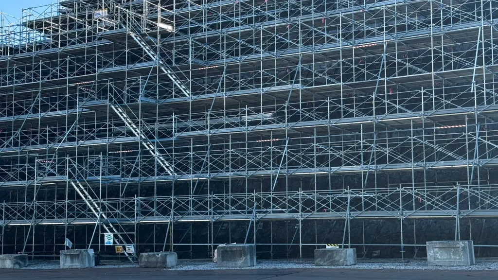
The same general scaffold geometry can serve different work activities. Workers may use one area primarily for access, while another area may temporarily receive tools or materials. Material delivery routes, building projections, limited site space and the location of working areas can all affect how the scaffold is used in practice.
For that reason, I consider it important not to treat the loading condition as an isolated number on a drawing.
The relationship between the intended work, working platforms, scaffold geometry and actual site constraints should be reviewed together.
It is also important to distinguish the load specified as a design condition from the allowable capacity of the scaffold components being used. They are not automatically the same thing.
This is a practical design principle rather than a universal regulatory rule.
Requirements vary by country, jurisdiction, project and scaffold system. Always confirm applicable local regulations, project specifications and manufacturer instructions.
Scaffold Load Review Checklist
Before finalizing or reviewing a scaffold loading assumption, check:
- ☑ Is the intended scaffold use clearly defined?
- ☑ Are the applicable regulation, standard and project requirements identified?
- ☑ Is the required load class or design loading clearly stated?
- ☑ Have workers, tools, equipment and materials been considered?
- ☑ Could materials become concentrated in one location?
- ☑ Are concentrated or partial-area loads relevant?
- ☑ Are material-storage areas identified separately?
- ☑ Are loading bays or hoisting interfaces treated separately where necessary?
- ☑ Is the number of simultaneously loaded working levels defined?
- ☑ Are the actual deck type and deck length suitable?
- ☑ Are supporting components suitable for the required loading?
- ☑ Has the load path through the scaffold been considered?
- ☑ Have reactions at the scaffold base/support been considered where required?
- ☑ Has manufacturer technical documentation been checked?
- ☑ Are important loading limitations communicated on the design or associated documentation?
- ☑ Would a change in work method require the loading assumption to be reviewed?
If several of these questions cannot be answered, the loading basis may not yet be sufficiently defined for the design to proceed without further information.
FAQ
Is Scaffold Load Class 3 Always 2.0 kN/m²?
Within the EN 12811-1 working-area classification, Class 3 has a nominal uniformly distributed load of 2.00 kN/m². However, that figure should not be treated as a universal scaffold capacity or automatically applied outside the relevant EN design framework. Manufacturer documentation and the actual scaffold configuration must also be checked.
Does a Higher Load Class Mean the Entire Scaffold Can Carry More Weight?
Not in that simple sense.
The load class defines specified working-area loading requirements. The complete scaffold must still be assessed for how loads are transferred through its decks, supporting members, standards, bases and supporting structure or ground.
Can I Determine the Load Class From the Type of Construction Work?
The work type can provide useful context, but it should not be the only basis for selection.
Actual numbers of workers, tools, materials, equipment, material-storage arrangements and simultaneous working levels should be considered.
Can EN Load Classes Be Directly Converted to OSHA Duty Ratings?
They should not be treated as direct equivalents.
OSHA uses its own regulatory framework based on requirements including maximum intended load and scaffold/component capacity. EN 12811 working-area load classes are a different classification system.
What Happens if the Scaffold Use Changes After Design?
If the change can alter the loading—for example, additional material storage, equipment or loaded working levels—the design assumptions should be reviewed before the scaffold is used under the changed condition.
Related Topics
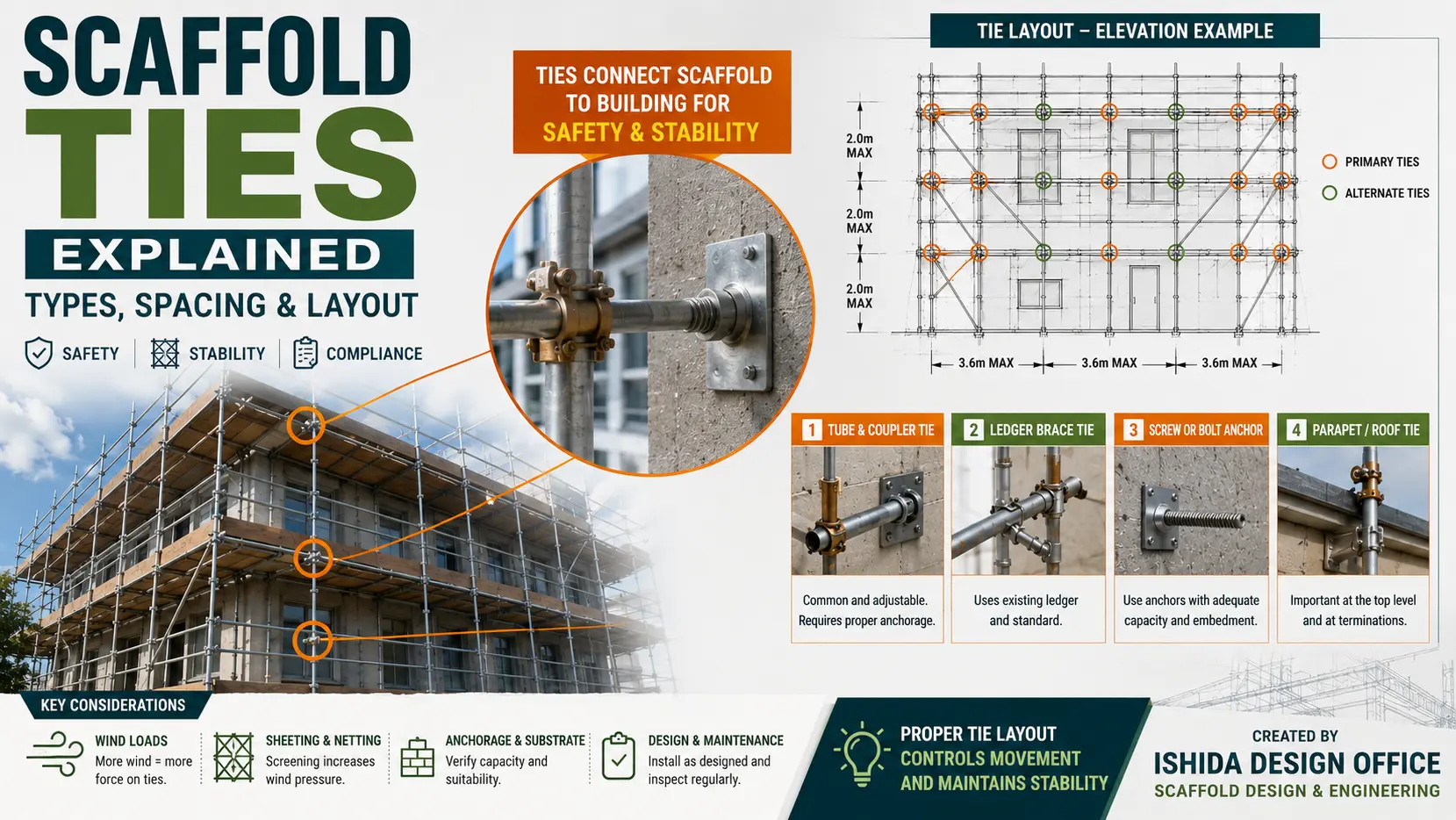
Load-class decisions are easier to apply when they are connected to scaffold geometry, drawings and stability.
For the geometry behind bay length, lift height and scaffold width, continue with Scaffold Dimensions Explained: Bay Length, Lift Height, Width & Standards.
For a broader drawing-review perspective, see How to Read Scaffold Drawings: Plan, Elevation, Section & Details.
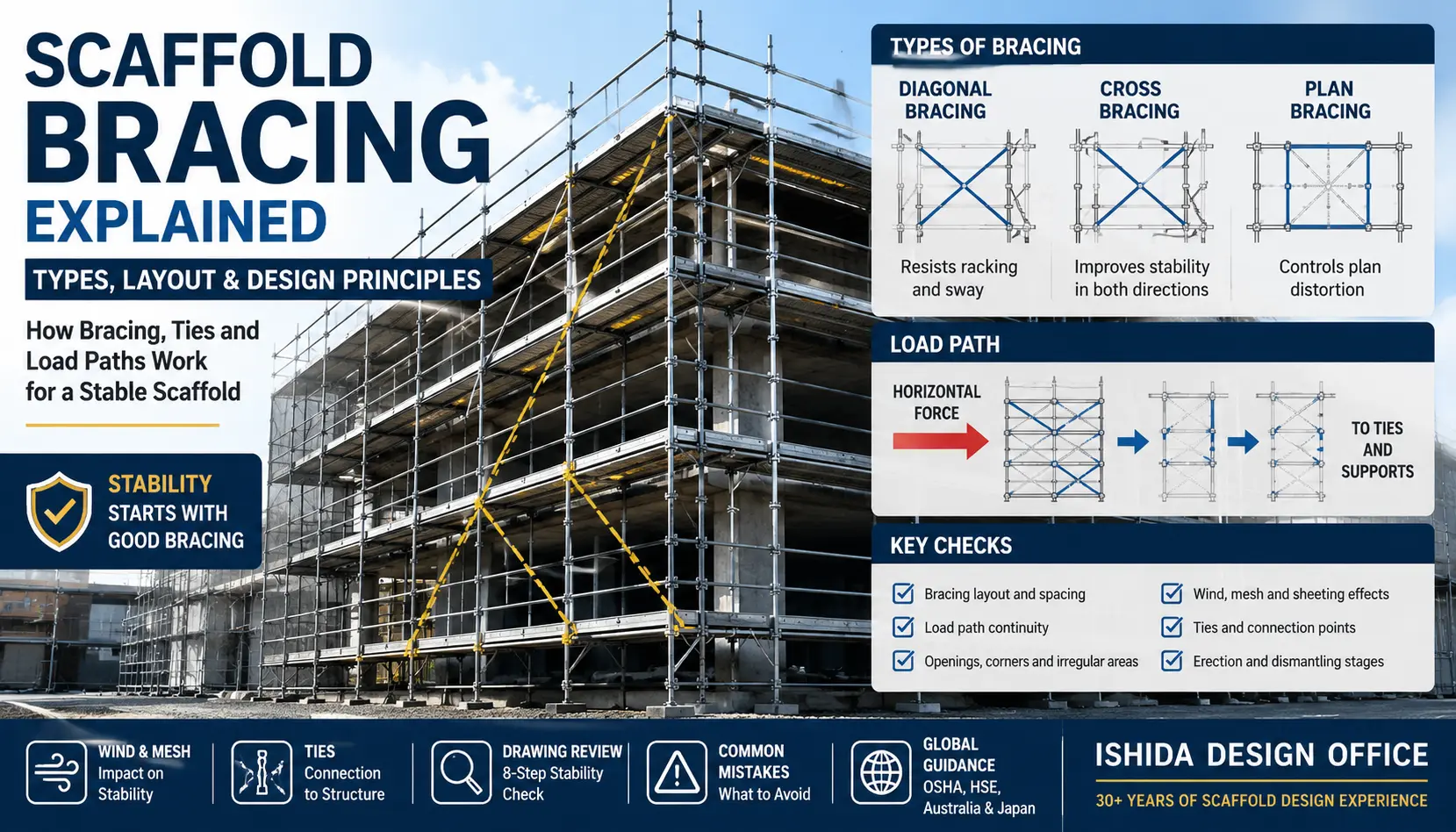
For the relationship between geometry and stability, see Scaffold Bracing Explained: Types, Layout & Design Principles.

Key Takeaways
- Load class is not the same as total scaffold capacity.
- EN 12811-1 defines six working-area load classes from 0.75 to 6.00 kN/m² for uniformly distributed loading.
- Uniformly distributed load is only part of the loading picture; concentrated and, for relevant classes, partial-area loading also matter.
- Scaffold use should be understood before the loading condition is selected.
- Material location can matter as much as total material weight.
- Multiple loaded levels can change loads transmitted through the supporting structure.
- Component and deck suitability must be checked against the actual scaffold system and manufacturer documentation.
- EN, OSHA and Australian duty classifications should not be presented as interchangeable systems.
Conclusion
The most important question in scaffold load-class selection is not simply:
“Which class should I use?”
It is:
FINAL DESIGN QUESTION
“How will this scaffold actually be used, where will the loads occur, and how will those loads travel through the structure?”
Once those conditions are understood, the applicable load classification becomes part of a much clearer design basis.
For designers, that distinction helps prevent one of the most fundamental scaffold-loading errors: confusing a working-platform load classification with the capacity of the complete scaffold.
Official References
United States — OSHA
OSHA — 29 CFR 1926.451, General Requirements for Scaffolds
OSHA’s primary regulation covering scaffold capacity, design and loading requirements.
OSHA — Scaffolding General Requirements eTool
Official OSHA explanatory guidance covering scaffold capacity and platform requirements.
OSHA — Interpretation of Maximum Intended Load and the 4-to-1 Requirement
Official interpretation explaining how maximum intended load applies to scaffold components.
Australia — Safe Work Australia
Safe Work Australia — General Guide for Scaffolds and Scaffolding Work
Official national guidance describing light-, medium- and heavy-duty working-platform classifications.
Manufacturer Technical Documentation
PERI — PERI UP Easy Technical Documentation
Official manufacturer documentation showing EN 12811 load classes and permitted deck configurations.
Layher — Industrial Scaffolding System Solutions
Official manufacturer documentation showing how permitted EN load classes vary with deck configuration and length.
Hünnebeck — BOSTA 100 Technical Documentation
Official manufacturer documentation used to verify EN 12811 partial-area load values for Classes 4–6.
Last Verified
September 2026
External official guidance and manufacturer documentation referenced in this article were checked at the time of writing. Regulations, standards and technical requirements may change. Always confirm the latest applicable requirements with the relevant authority, project documentation and scaffold manufacturer.
About the Author
ISHIDA DESIGN OFFICE brings more than 30 years of practical experience in Japan, specializing in scaffolding design, temporary works planning, CAD drafting, quantity estimation, and construction support.
Drawing on experience from residential, commercial, and industrial projects, he shares practical insights that emphasize not only sound engineering design but also buildability, safety, and real-world jobsite application.
At Scaffold Design Hub, he combines practical experience from Japan with official guidance and technical resources from government agencies, manufacturers, and industry organizations around the world to provide reliable, practical information for construction professionals.
To learn more, visit the About page. For questions or project inquiries, please use the Contact page.