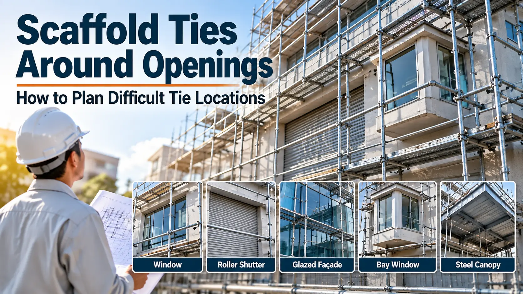
A scaffold tie pattern can look perfectly regular on an elevation until it reaches the building.
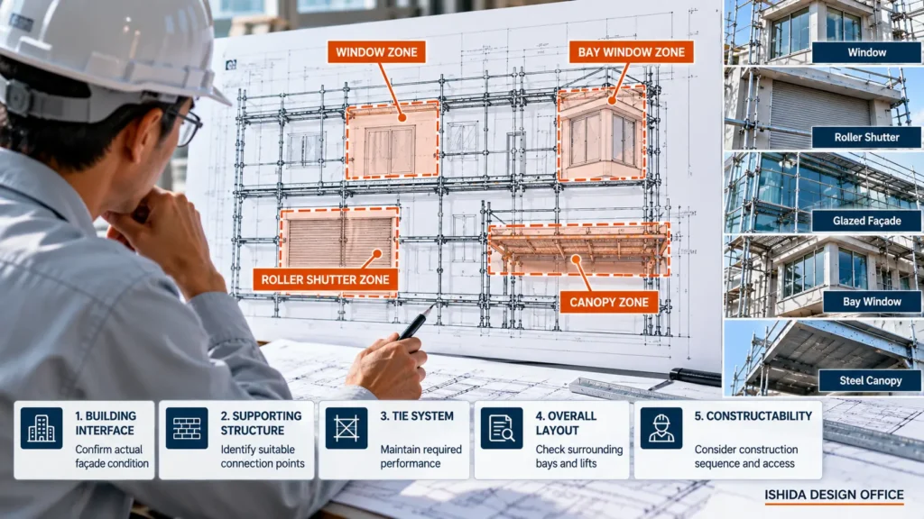
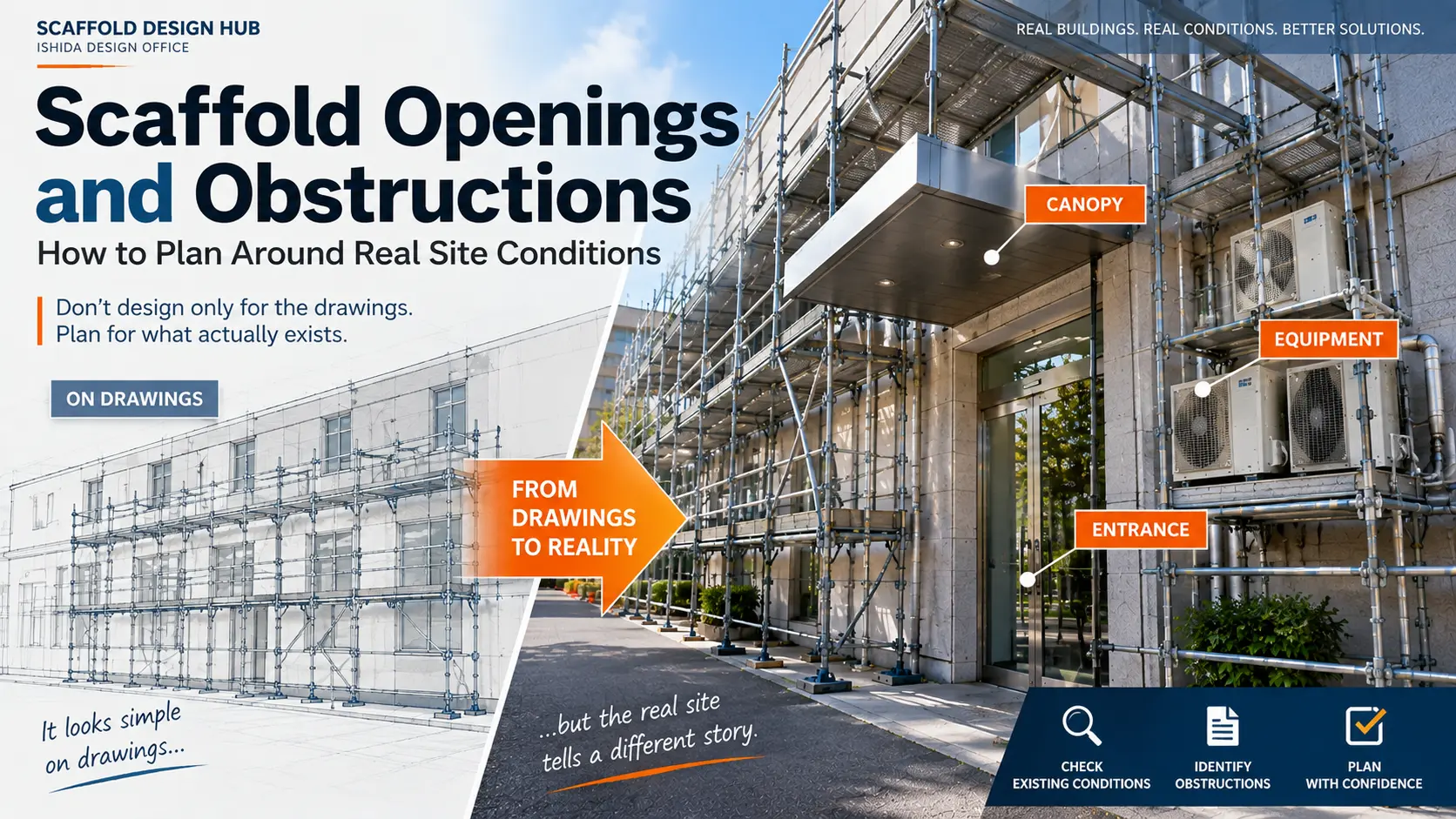
A window occupies the intended fixing point. A roller shutter takes up most of a bay. The façade is glazed. A bay window projects from the wall. On an industrial building, a large steel canopy may interrupt both the scaffold geometry and the available connection points.
This is where tie planning becomes less about drawing a regular pattern and more about understanding the actual building interface.
The practical question is not simply:
“Where should the next tie symbol go?”
It is:
“Where can this scaffold actually be connected to suitable supporting structure while maintaining the required design?”
That distinction matters.
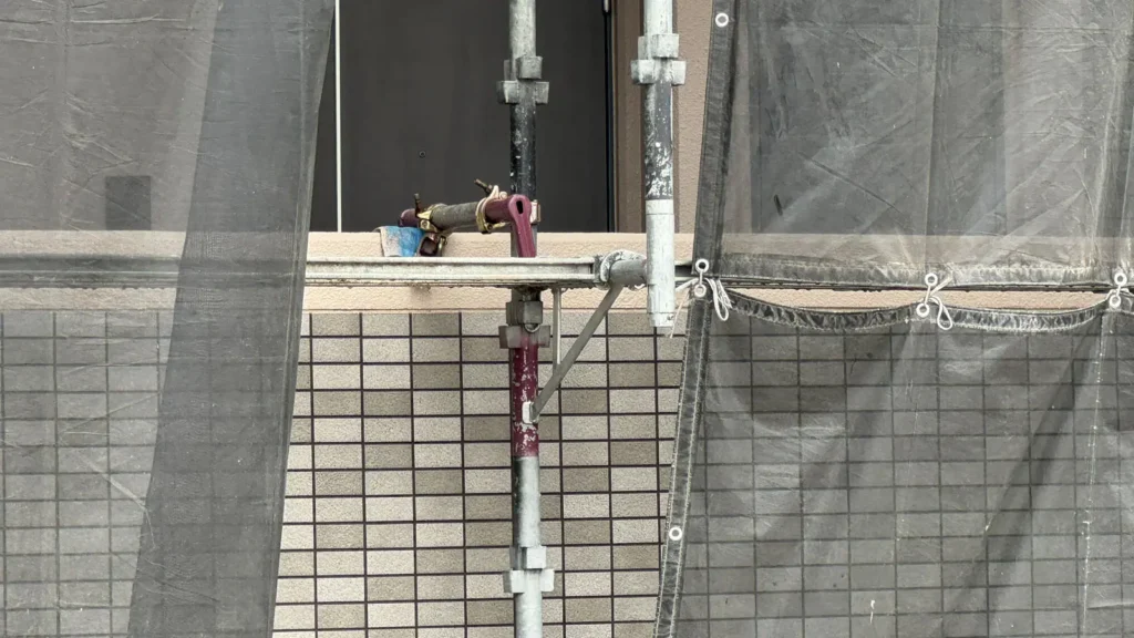
The Tie Position on the Drawing Is Not Always Available on the Building
Scaffold ties are part of the stability system. Their locations should therefore not be treated as marks that can simply be moved around an elevation for convenience.
In my design work, difficult tie locations frequently arise around roller shutters, glazed façades, bay windows and buildings with large projecting steel canopies.
The common issue is straightforward: the position that works for the scaffold layout may not correspond to a suitable connection point on the building.
That can become apparent during drawing review. It can also become apparent later when more detailed building information or site conditions are available.
Either way, the next step should be review, not improvisation.
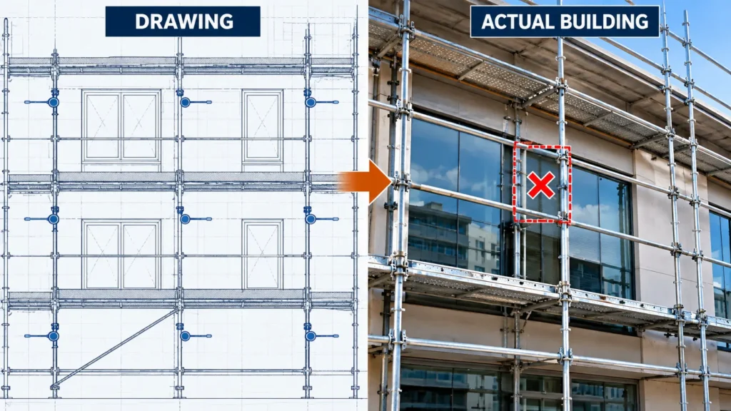
SafeWork NSW makes a similar distinction in its industry safety standard: the type and position of scaffold ties can vary considerably from project to project because the available supporting structure and construction process affect the tie layout. Its guidance says tie design should contain enough information for the arrangement to be followed on site without interpretation. SafeWork NSW
Why Openings Disrupt Otherwise Regular Tie Layouts
Openings affect tie planning in different ways. It is useful to identify what is actually preventing the intended connection rather than grouping every problem under the word “opening.”
Windows and repeated façade openings
A single window may only affect one local position.
A façade with repeated windows can be much more restrictive because the problem repeats horizontally and vertically. A regular scaffold bay arrangement and a regular architectural window grid do not necessarily produce usable tie positions at the same locations.
This becomes especially important when reviewing the elevation as a whole rather than solving one tie in isolation.
Roller shutters and large openings
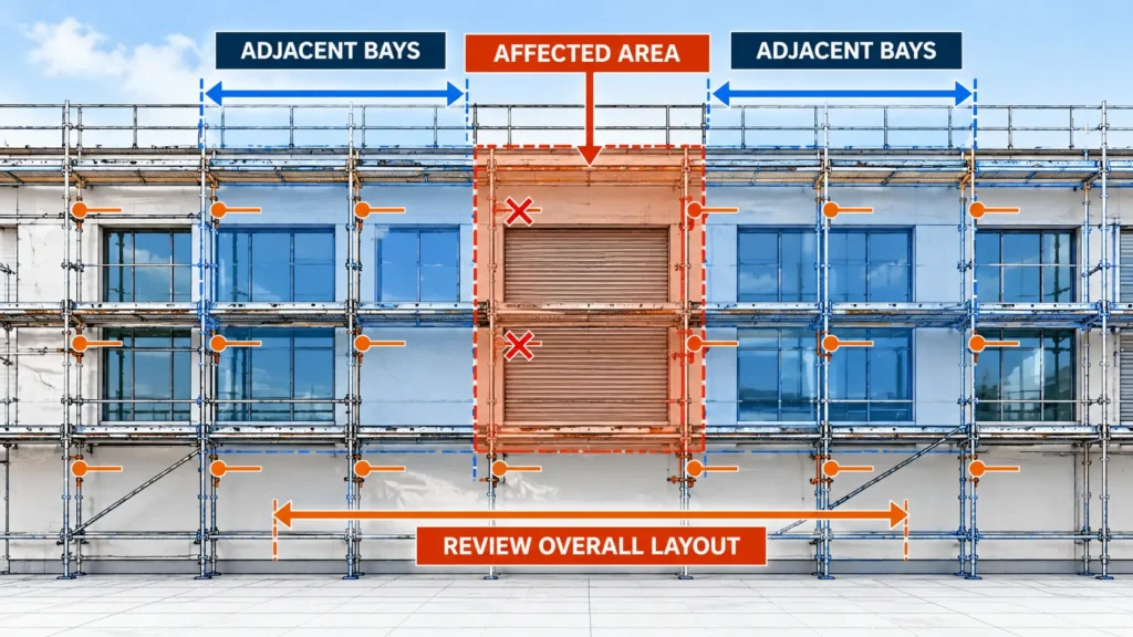
Large roller shutters can remove a substantial portion of the wall area that might otherwise appear available for attachment.
This is common enough in practical design work that I would not assume a regular tie layout can simply continue across the opening.
The supporting structure around the shutter needs to be understood.
Glazed façades
Glass is an obvious warning sign on a scaffold elevation.
What appears on a general drawing as the face of a building may actually consist largely of glazing and façade systems. The relevant question is therefore not merely where the façade line is located, but what suitable supporting structure is actually available for the proposed tie system.
This is one reason architectural information alone may not be enough for final tie planning.
Bay windows and projections
A bay window creates another problem: the façade is no longer a single flat plane.
The projection can affect scaffold clearance, bay arrangement and the relationship between the scaffold and potential tie locations.
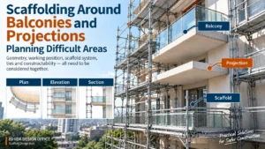
This overlaps with the broader problem of scaffolding around balconies and projections, but the specific concern here is the tie interface.
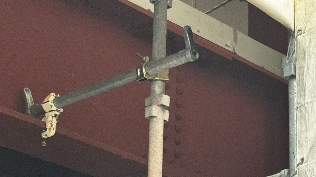
Large steel canopies and other obstructions
Industrial buildings can present a different type of problem.
A large projecting steel canopy may interrupt the normal relationship between scaffold and building over a significant area. Services, signs, plant and other fixed features can create similar local restrictions.
The geometry may still be drawable.
The tie arrangement may not be.
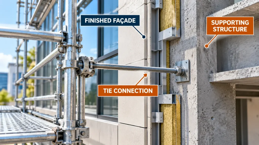
Start With the Supporting Structure, Not Just the Opening
When an intended tie position cannot be used, the most useful question is not:
“How far can I move this tie?”
First ask:
“What can the tie actually connect to?”
That changes the review from a graphical exercise into a structural-interface check.
Is there actually a suitable attachment location?
The available location should correspond to supporting structure appropriate for the proposed tie or anchorage system.
A façade surface should not automatically be assumed to provide that support.
The supporting material and structural arrangement need to be identified from suitable project information.
SafeWork NSW guidance states that scaffold tie design should consider the anchorage type, fixing type, substrate, number and pattern/location. SafeWork NSW
What is behind the finished façade?
This is particularly relevant for panels and other finished façades.
In practical design work, the drawing and the actual attachment conditions do not always match as neatly as expected. Where a finished panel system is present, for example, the façade construction and available joints or structural interfaces may need further investigation rather than assuming the visible surface can accept the intended fixing.
The objective is not to find a convenient hole in the façade.
It is to identify an appropriate connection to the supporting structure.
Can the proposed anchorage resist the required actions?
Once a possible attachment point has been identified, the connection itself still needs to be verified.
Anchor and tie capacities should not be assumed from appearance or from previous projects. The actual manufacturer information for the product being used should be checked together with the relevant substrate and installation conditions.
SafeWork NSW also advises checking the structure and material to which drilled-in anchors will be applied and installing anchors according to the manufacturer’s instructions. SafeWork NSW
This is one of the places where a small symbol on a drawing represents a much larger engineering question.
What to Review When the Intended Tie Location Cannot Be Used
There is no universal replacement detail for every blocked tie location.
That is precisely why the condition needs review.
Rather than publishing a fixed sequence that could be copied into unsuitable projects, I find it more useful to identify the questions that need to be resolved.
Available supporting structure
Determine what suitable structural locations are actually available around the affected area.
That may require architectural drawings, structural drawings, sections, façade information, photographs, site dimensions or clarification from the project team.
DO NOT ASSUME: If the necessary information is missing, do not invent the building behind the façade. Get the missing information.
Tie position and overall layout
A possible alternative position should not be reviewed as an isolated point.
Look at the surrounding tie arrangement as well.
An adjustment at one opening may affect the spacing and pattern around adjacent bays or lifts. A solution that appears reasonable locally can create another problem nearby.
This article deliberately stops short of prescribing a universal alternative tie pattern. That belongs to the project-specific design.
The principle is more important:
Review the arrangement as a system, not as individual dots on an elevation.
Tie and anchorage system
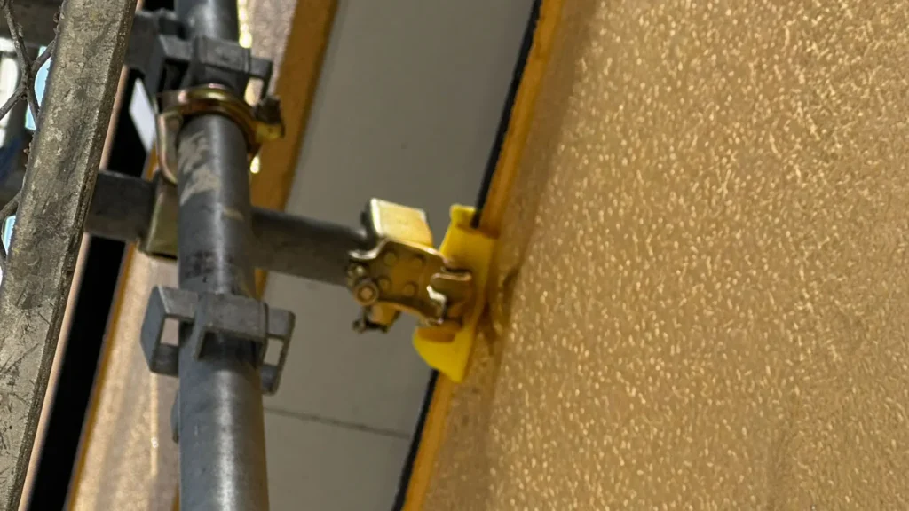
The original tie or fixing arrangement may not suit the available building interface.
Where an alternative tie arrangement or component is considered, its actual configuration, compatibility, manufacturer information and structural function need to be reviewed rather than assuming that different components are interchangeable.
The supplied project information and manufacturer documentation should govern the final selection.
Loads and design assumptions
Tie locations are connected to loads.
If a tie position changes, the designer needs to consider whether the revised arrangement remains consistent with the design assumptions and required resistance.
This becomes particularly important when the scaffold is sheeted or otherwise exposed to significant wind actions.
SafeWork NSW notes that sheeted scaffolds can require more ties and that supporting-structure limitations may affect where ties can be located. SafeWork NSW
For the detailed load side of this subject, see Scaffold Tie Loads rather than treating this article as a duplicate tie-load guide.
Construction sequence and access
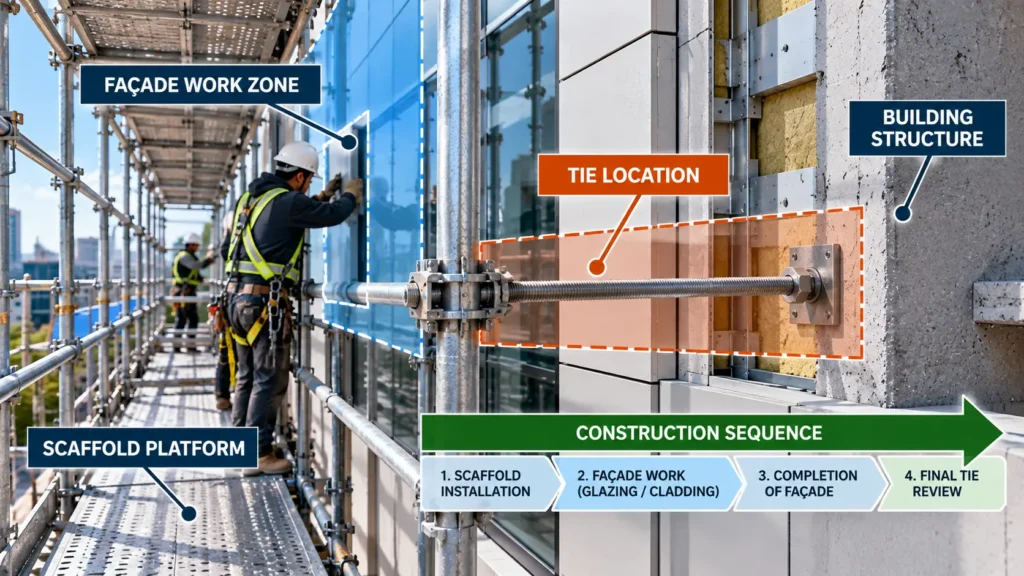
A tie that works structurally can still create a practical problem if it conflicts with the work that the scaffold exists to support.
Glazing, cladding, painting and other façade work can all interact with tie positions.
SafeWork NSW specifically warns against unplanned removal or alteration of ties by finishing trades seeking access to walls and openings. Its guidance recommends planning work so that construction can proceed without uncontrolled changes to the scaffold ties. SafeWork NSW
That makes construction sequence part of tie planning—not something to think about after the drawing is issued.
Moving a Tie Is a Design Change, Not a Drawing Adjustment
This point deserves emphasis.
When an intended tie location is unavailable, dragging the tie symbol sideways in CAD does not solve the engineering problem.
The revised position may change the relationship between the scaffold, the supporting structure and the surrounding tie layout.
The revised connection may also require different project information or component verification.
Official guidance illustrates why this matters.
Under U.S. OSHA rules for supported scaffolds covered by 29 CFR 1926.451(c)(1), guys, ties and braces are part of the measures used to restrain qualifying scaffolds from tipping, and their placement is governed by the applicable requirements or manufacturer recommendations. These are U.S.-specific requirements and should not be treated as universal international spacing rules. U.S. Occupational Safety and Health Administration (OSHA)
Australian guidance similarly says that if ties cannot practically be positioned according to the applicable instructions, the scaffold designer, manufacturer, supplier or an engineer should be consulted. Workplace Health and Safety Queensland
Different jurisdictions express the requirements differently, but the practical lesson is consistent:
IMPORTANT: Do not treat a changed tie position as a cosmetic drawing revision.
Why Tie Quantity Should Not Be Reduced Just Because the Location Is Difficult
A difficult façade creates pressure to simplify the drawing.
That pressure should not determine the tie design.
One principle I follow is straightforward:
IMPORTANT: Do not reduce the number of ties simply because the intended attachment locations are inconvenient.
The required arrangement has to remain consistent with the applicable design, loads, manufacturer information, project requirements and local regulations.
If the planned location is unavailable, that is a design problem to resolve—not a reason to silently remove the tie.
This is also why manufacturer capacities matter. The capacity of an anchor, fixing or proprietary tie component should be checked rather than assumed.
Japan provides a useful example of why local rules must remain jurisdiction-specific. Japan’s Industrial Safety and Health Regulations prescribe maximum wall-tie or stay intervals for certain types of steel scaffolds. Those Japanese numerical requirements should not be transferred to projects in other jurisdictions as universal values. Japan Ministry of Health, Labour and Welfare
The correct values for a particular project must come from the rules, design documentation and product information that actually apply to that project.
A Practical Drawing Review for Openings and Difficult Tie Locations
A useful review starts before the final tie symbols are treated as fixed.
On an elevation, I would look at the building interface and ask questions such as:
- Where are the windows and doors?
- Are there roller shutters?
- Is the façade glazed?
- Are there bay windows or other projections?
- Are there balconies or canopies?
- Are façade panels hiding the structural substrate?
- Is the available supporting structure shown clearly enough?
- Are there services or equipment in the intended tie zone?
- Will façade work later require access to the same location?
- Does the proposed tie arrangement remain consistent with the design conditions?
- Has the actual tie/anchor product information been checked?
Notice what this checklist does not do.
It does not provide a universal formula for relocating a tie.
That would ignore differences in scaffold systems, building structures, tie products, loads, wind conditions, project requirements and jurisdictions.
What the Scaffold Drawing Should Communicate
A difficult tie arrangement should not rely on the site team guessing what the designer intended.
Where relevant, the drawing should clearly communicate the approved tie locations and enough information to identify the intended arrangement.
SafeWork NSW’s industry standard states that tie design information should be sufficient for the arrangement to be followed on site without interpretation. SafeWork NSW
Depending on the project, relevant documentation may need to identify or reference:
- tie locations;
- tie type or relevant system information;
- required anchorage information;
- supporting structure or substrate considerations;
- special areas where the normal arrangement changes;
- relevant design notes;
- restrictions on moving or removing ties.
The exact level of documentation depends on the project and system.
But there is a simple test:
Could someone looking at the drawing mistake the difficult area for a normal bay?
If yes, the drawing probably needs to communicate more.
Illustrative Example: A Large Opening Interrupts the Intended Tie Layout
Consider a scaffold elevation with a large building opening.
The initial layout places a tie where the opening prevents the intended connection.
The wrong response would be to delete the tie or move its symbol to an arbitrary nearby point.
A proper review would instead establish what supporting structure is available around the opening, verify the relevant connection and component information, examine the surrounding tie arrangement, and confirm that the resulting configuration remains consistent with the project design.
In actual design work, I have encountered large openings where the originally expected tie position could not be used. The response required reviewing the available structure and changing the arrangement rather than simply accepting the missing tie.
The exact alternative detail is project-specific and is intentionally not reproduced here.
The lesson is the important part:
An unavailable tie location triggers a design review. It does not cancel the design requirement.
From My Design Work: Reviewing Scaffold Ties at a Glazed Façade
In one of my scaffold design projects involving a glazed façade, I identified a problem with the planned scaffold tie arrangement while preparing and reviewing the CAD drawings.
Rather than treating this as a simple adjustment to the drawing, I reviewed the tie positions together with the reinforcing members.
I subsequently changed the arrangement of both the scaffold ties and the reinforcing members and prepared a structural calculation report for the revised design.
This experience illustrates why I do not review tie locations as isolated points on an elevation drawing. When the building interface creates a problem, the revised arrangement needs to be considered as part of the scaffold’s overall structural system.
For me, the important lesson is that a practical-looking tie position on a CAD drawing is not enough. The actual building conditions, the revised structural arrangement and the necessary engineering verification must be considered together.
Scaffold Tie Location Review Checklist
Before finalising ties around openings or difficult façade areas, check:
Building interface
- Have all major openings been identified?
- Are shutters, glazing, projections and canopies shown?
- Is the façade construction understood?
- Is suitable supporting structure identifiable?
Tie system
- Is the proposed tie appropriate for the available connection?
- Is the anchorage/fixing appropriate for the substrate?
- Has relevant manufacturer documentation been checked?
- Are assumptions about the building connection documented?
Layout
- Has the surrounding tie arrangement been reviewed after any location change?
- Does the revised arrangement remain consistent with the design?
- Have adjacent bays, lifts, ends and unusual geometry been considered where relevant?
Loads
- Are the applicable tie actions/design loads established?
- Have wind and containment conditions been considered where relevant?
- Have project-specific loading conditions been retained after the change?
Constructability
- Can the tie actually be installed?
- Does it conflict with glazing, cladding or other façade work?
- Is there a risk that another trade will later need the tie removed?
- Is the intended arrangement clear enough to avoid site improvisation?
Documentation
- Are unusual tie locations clearly shown?
- Are necessary notes and references included?
- Can the site team identify which areas differ from the normal arrangement?
- Is further engineering review clearly identified where required?
This checklist is intentionally a review tool, not a substitute for project-specific engineering.
FAQ
Can a scaffold tie simply be moved sideways when it conflicts with a window?
Not automatically. The revised location should be checked against the available supporting structure, tie arrangement, design actions, connection system, manufacturer information and applicable project requirements.
Can a tie be omitted if there is no suitable fixing point at the intended location?
Difficulty installing a tie is not, by itself, justification for removing a required tie. The arrangement should be reviewed and an appropriate project-specific solution developed.
Can scaffold ties be attached around window or door openings?
Some scaffold systems and designs can use structural features around openings, but suitability depends on the actual supporting structure, tie arrangement, loads and connection details. Do not assume that every opening provides an acceptable tie location.
What information should be checked before selecting a scaffold anchor?
At minimum, the proposed tie system, fixing or anchor, substrate/supporting structure, relevant actions and manufacturer’s applicable installation and capacity information should be reviewed.
Why are glazed façades difficult for scaffold tie planning?
Because the visible façade does not necessarily provide suitable structural attachment locations. The designer may need more information about the building structure and façade system before finalising the tie arrangement.
Related Topics
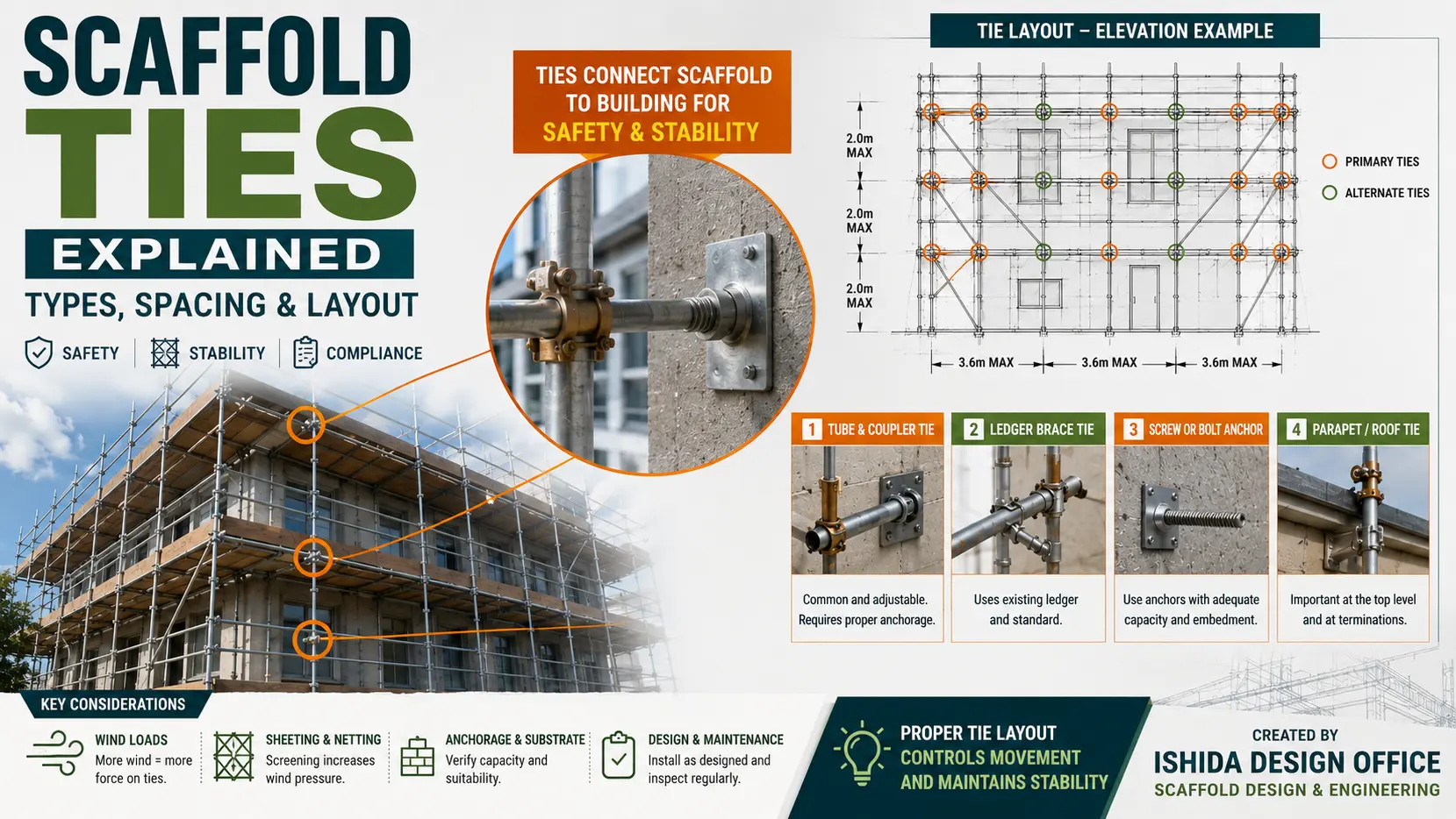
Scaffold Ties Explained: Types, Spacing & Layout — Use this for the fundamentals before dealing with difficult opening conditions.
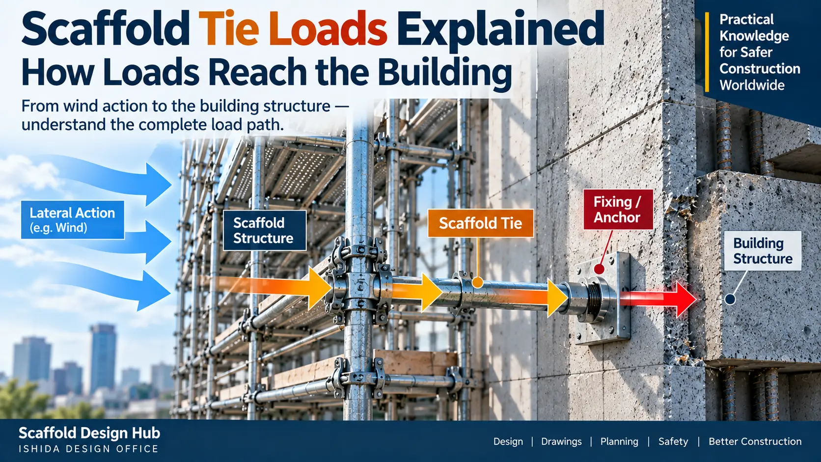
Scaffold Tie Loads — Use this when the reader needs to understand the forces rather than the building-interface problem.
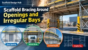
Scaffold Openings and Obstructions: How to Plan Around Real Site Conditions — This expands the discussion beyond ties to the overall scaffold arrangement.
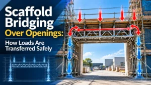
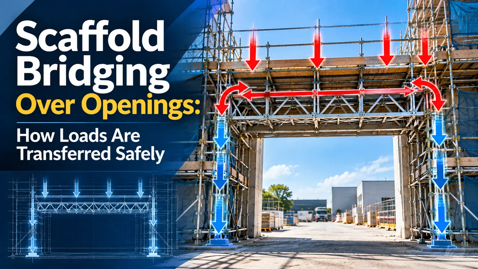
Scaffold Bridging Over Openings: How Loads Are Transferred Safely — This covers the different problem of carrying the scaffold over an opening.
Scaffold Tie Patterns Explained: How Layout Affects Stability — This future article will explain overall tie-pattern behaviour without duplicating the opening-specific planning covered here.
Key Takeaways
- A regular tie grid on a drawing does not guarantee that suitable attachment locations exist on the building.
- Windows, roller shutters, glazing, bay windows and large projecting canopies can disrupt intended tie positions.
- When a location is unavailable, review the supporting structure, connection system, surrounding tie arrangement and design conditions rather than simply moving the drawing symbol.
- Tie or anchor capacity should be checked against applicable manufacturer information and project conditions.
- A difficult location is not, by itself, justification for reducing the required tie arrangement.
- Unusual tie locations should be communicated clearly enough that they do not depend on site interpretation.
- Tie requirements vary by scaffold system, project, manufacturer and jurisdiction.
Conclusion
Openings make scaffold tie planning difficult because they expose the difference between a regular drawing pattern and the actual building.
The most useful habit is therefore simple: check what is really available to connect to before treating the tie layout as final.
If an intended position cannot be used, review the supporting structure, connection, surrounding layout and design conditions. Do not solve the problem by quietly deleting a tie or moving a symbol.
For the next technical step, the tie-load article explains the forces behind these connections, while the planned tie-pattern article will examine how the overall layout relates to scaffold stability.
Official References
- U.S. Occupational Safety and Health Administration (OSHA) — 29 CFR 1926.451, General Requirements for Scaffolds. Used for U.S.-specific supported-scaffold restraint requirements. OSHA
- SafeWork NSW — Scaffolding Industry Safety Standard, Appendix C: Scaffold Ties. Used for tie-design information, supporting-structure considerations, anchorage/substrate considerations and documentation of tie layouts. SafeWork NSW
- SafeWork NSW — Erecting, Altering and Dismantling Scaffolding – Part 1. Used for supporting-structure and drilled-anchor checks. SafeWork NSW
- Workplace Health and Safety Queensland — Scaffolding Code of Practice 2021. Used for guidance on situations where intended tie positions are impractical and require consultation/review. WorkSafe Queensland
- Japan Ministry of Health, Labour and Welfare — Industrial Safety and Health Regulations. Used only to illustrate Japan-specific wall-tie/stay provisions; these numerical requirements are not presented as international rules. Japan Ministry of Health, Labour and Welfare
Last Verified: September 2026
Regulations, official guidance and manufacturer documentation may change. Always confirm the current requirements applicable to the project location, scaffold system and intended use.
This article is general technical information and is not a substitute for project-specific engineering, applicable law, contract documents, project specifications, manufacturer instructions or competent professional review.
About the Author
ISHIDA DESIGN OFFICE brings more than 30 years of practical experience in Japan, specializing in scaffolding design, temporary works planning, CAD drafting, quantity estimation, and construction support.
Drawing on experience from residential, commercial, and industrial projects, he shares practical insights that emphasize not only sound engineering design but also buildability, safety, and real-world jobsite application.
At Scaffold Design Hub, he combines practical experience from Japan with official guidance and technical resources from government agencies, manufacturers, and industry organizations around the world to provide reliable, practical information for construction professionals.
To learn more, visit the About page. For questions or project inquiries, please use the Contact page.