A scaffold can look straight, complete and perfectly usable—and still have a stability problem.
When I review a scaffold drawing, one of the first things I look for is not the platform or even the guardrail. I look at the stability system.
Where are the braces? Where are the ties? What happens around openings? And most importantly:
If the scaffold is pushed sideways, where does that force go?
That question is at the heart of scaffold bracing.
I have worked with temporary works, scaffold design and scaffold drawings for more than 30 years. One lesson has stayed with me throughout that time: stability problems do not always begin with complicated engineering.
Sometimes the issue is much simpler. A brace is missing. A tie position has changed. An entrance interrupts the intended bracing pattern. Sheeting is added after the original arrangement has been agreed. Or someone assumes that another component can perform the same structural function.
This guide explains scaffold bracing types, layout and design principles from a practical drawing-review and site perspective.
- What scaffold bracing actually does
- The main types of scaffold bracing
- The difference between braces, ties and guardrails
- How horizontal forces move through the scaffold
- How I review scaffold bracing layout
- What to check around openings, corners and special areas
- Why mesh and sheeting can change stability demand
- Common scaffold bracing mistakes
- Japanese practice and international guidance
Do not look only at the brace. Follow the load path.
Requirements vary by country, jurisdiction, scaffold system and project. Always follow local laws, approved project information and the scaffold manufacturer’s current instructions.
Why Scaffold Bracing Matters
Bracing helps a scaffold resist unwanted movement and maintain its intended geometry. It is particularly important when horizontal forces, construction activities, imperfections or unusual geometry try to distort the structure.
On a CAD elevation, a scaffold can look very orderly.
Standards are vertical.
Ledgers are horizontal.
Platforms repeat from lift to lift.
Everything appears straight.
But a scaffold is not a static picture.
Workers move on it. Materials are handled. Wind acts on it. Mesh or sheeting may be installed. Openings interrupt the regular grid.
And the completed scaffold must remain stable through all of those conditions.
Think About a Simple Rectangle
Imagine one scaffold bay as a rectangle. If the joints provide insufficient resistance and the top is pushed sideways, the rectangle can distort toward a parallelogram.
Now add a diagonal brace. The geometry becomes more resistant to that distortion because the diagonal helps create a triangulated load path.
What Bracing Helps Control
- Sway: side-to-side movement
- Racking: distortion of scaffold bays
- Displacement: movement of standards or frames from their intended position
- Local instability: instability within part of the scaffold arrangement
- Load transfer: movement of horizontal forces through the scaffold toward suitable restraints
OSHA 29 CFR 1926.451(c)(3), for example, requires supported scaffold poles, legs, posts, frames and uprights to be plumb and braced to prevent swaying and displacement. HSE similarly requires scaffolds to be adequately braced and tied to a permanent structure or otherwise stabilised.
The wording changes between jurisdictions. The engineering principle does not: a scaffold needs a reliable system for resisting movement and transferring horizontal forces.
What Is Scaffold Bracing?
Scaffold bracing refers to components or arrangements that help improve the stiffness and stability of a scaffold. A brace usually works as part of a wider structural system rather than acting alone.
That second point matters.
A scaffold is three-dimensional, so I think about stability in several directions:
- Longitudinal stability along the scaffold run
- Transverse stability across the scaffold width
- Horizontal or plan stability
- External restraint through ties, anchors or other designed systems
Basic Scaffold Bracing Terminology
| Term | Practical Meaning |
|---|---|
| Standard / Upright | Main vertical scaffold member |
| Ledger | Horizontal member running along the scaffold |
| Transom | Horizontal member across the scaffold width |
| Diagonal Brace | Inclined member used to improve stiffness or stability |
| Façade Brace | Bracing arranged along the scaffold elevation |
| Transverse Brace | Bracing acting across scaffold width |
| Plan Brace | Diagonal bracing in the horizontal plane |
| Cross Brace | Two diagonal members forming an X |
| Knee Brace | Short local diagonal brace |
| Tie | Connection providing restraint to a suitable permanent structure |
| Raker | Inclined stabilising support |
Terminology varies between countries, manufacturers and scaffold systems. For that reason, I pay more attention to function than to the name alone.
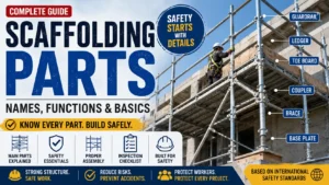
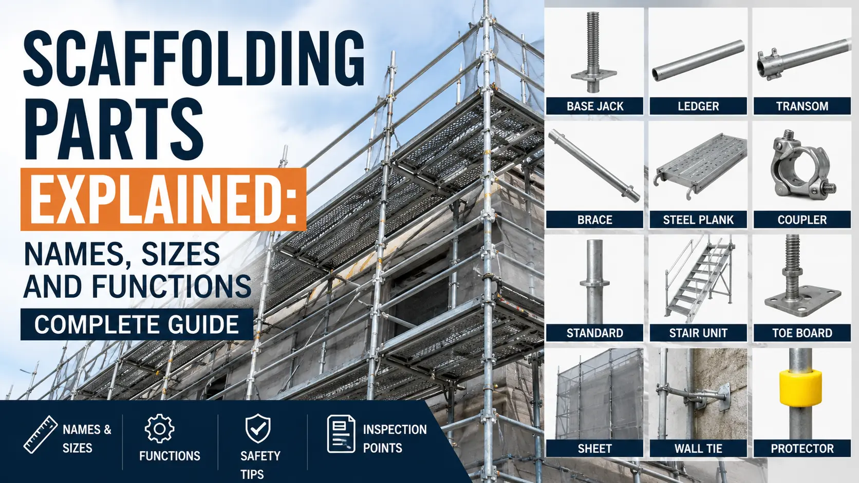
For a detailed reference to the names, sizes and functions of the main scaffold components, see Scaffolding Parts Explained: Names, Sizes and Functions (Complete Guide).
When I see a component on a drawing, I ask: “What is this member actually supposed to do?”
Types of Bracing in Scaffolding — With Pictures and Diagrams
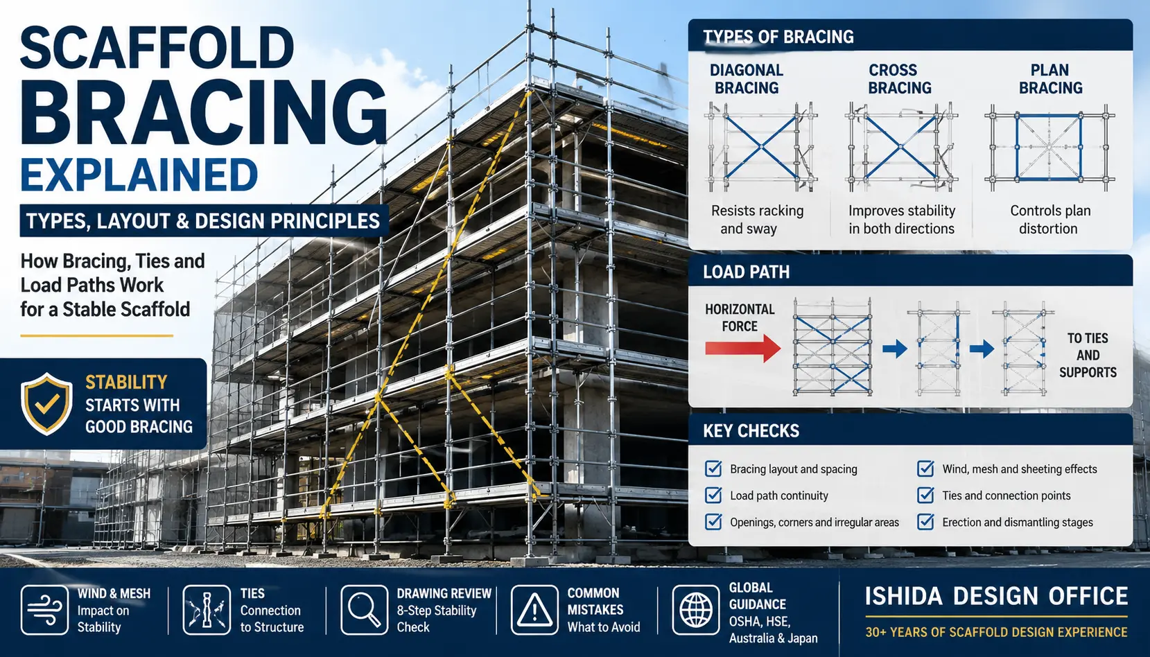
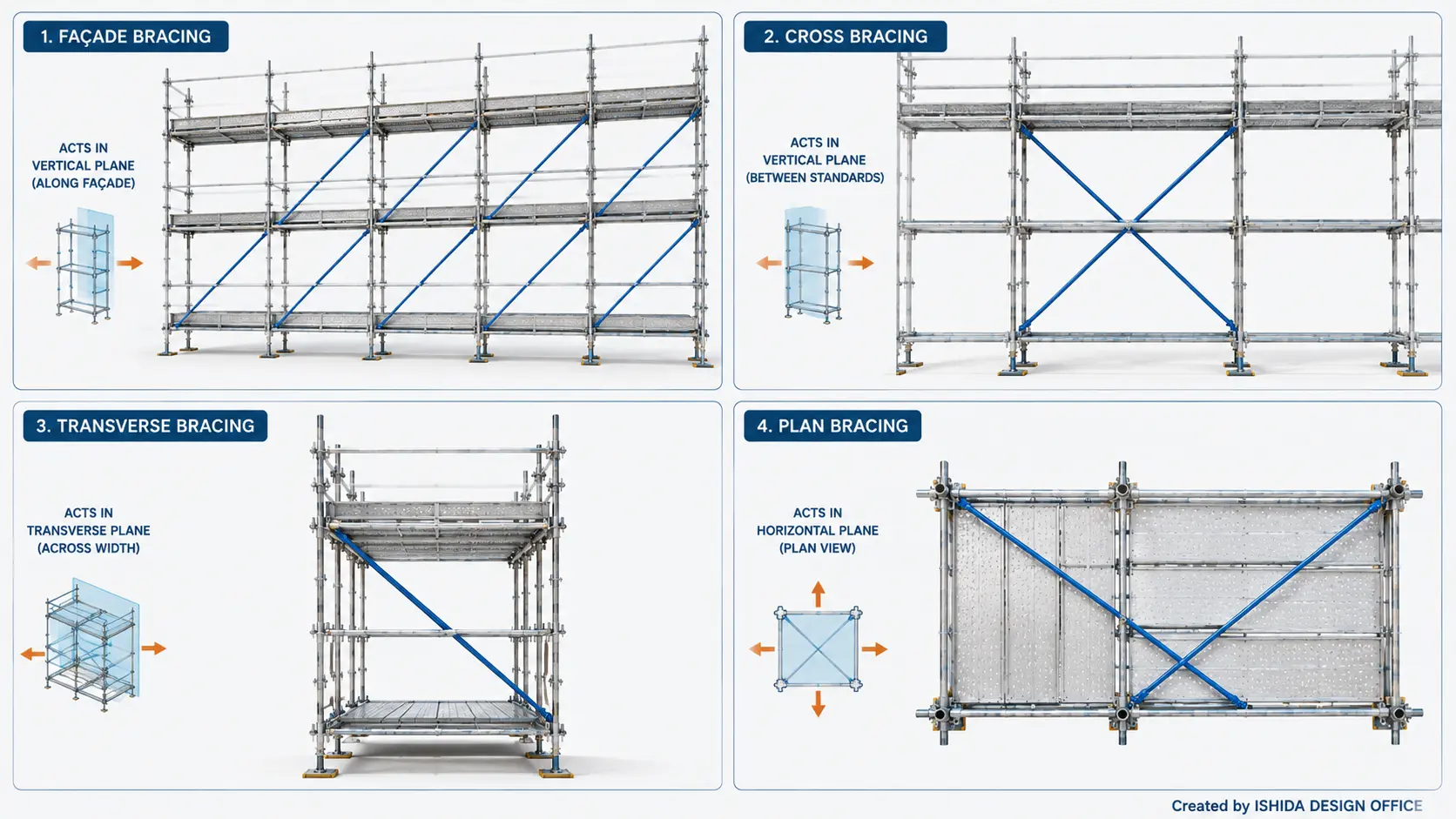
Scaffold bracing can take several forms depending on the direction of movement that needs to be controlled and the scaffold system being used. The main types include façade bracing, cross bracing, transverse bracing, plan bracing, knee bracing and rakers.
The pictures and diagrams below show where these different types of bracing can appear in a scaffold. Their exact arrangement, spacing and structural function depend on the scaffold system, geometry, loading, restraints, manufacturer requirements and project-specific design.
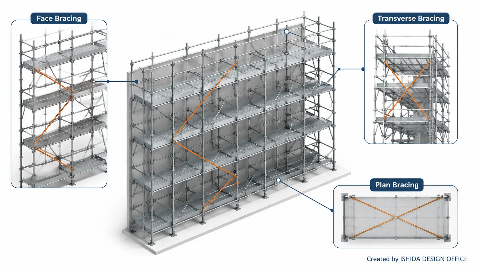
Quick Comparison of Scaffold Bracing Types
| Bracing Type | Where It Acts | Typical Function |
|---|---|---|
| Façade / Longitudinal Bracing | Along the scaffold elevation | Helps resist longitudinal racking and movement |
| Cross Bracing | Within a scaffold bay | Uses intersecting diagonals to improve stiffness |
| Transverse Bracing | Across the scaffold width | Helps control movement in the transverse direction |
| Plan Bracing | Horizontal plane | Helps transfer horizontal forces through the scaffold plan |
| Knee Bracing | Local areas | Provides local stiffness or support where required |
| Rakers | Outside the main scaffold | Can provide external stabilisation when properly designed |
Important: The names of bracing types are useful, but the structural function matters more. Always ask which direction the brace is stabilising and where the resulting force is transferred.
1. Façade or Longitudinal Bracing
This is the diagonal bracing most people recognise first. It runs along the scaffold elevation and contributes to longitudinal stiffness and resistance to racking.
- Single diagonals
- Repeated diagonals
- Zig-zag bracing
- X-bracing
- Larger continuous braced zones
The important question is not whether the pattern looks strong. It is whether the arrangement is correct for that scaffold system and design.
2. Cross Bracing
Cross bracing consists of two diagonals forming an X.
It is visually easy to recognise and is commonly associated with certain frame and tube scaffold arrangements.
However, the existence of an X does not by itself prove that the bay has adequate capacity.
Brace capacity, connections, angle, scaffold geometry, surrounding members and restraints still matter.
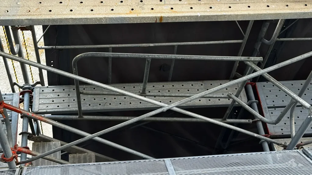
3. Transverse Bracing
Transverse bracing acts across the width of the scaffold. It is easy to overlook when the drawing review focuses only on the façade elevation.
A scaffold can appear well braced from the front while still requiring additional consideration in section.
4. Plan Bracing
Plan bracing acts in the horizontal plane and may become especially important in birdcage scaffolds, loading structures, bridging sections, stair towers, temporary roofs and other complex arrangements.
Plan → Elevation → Section
A problem that is invisible in one view may be obvious in another.
5. Knee Bracing
A knee brace is a shorter diagonal member used locally to improve stiffness or support a particular structural arrangement.
It can be very useful.
But a knee brace should not automatically be treated as a substitute for the primary bracing system.
6. Rakers
Rakers are inclined supports that may form part of an external stabilising arrangement.
Simply leaning a tube against a scaffold does not create a reliable stability system.
The footing, connection, restraint and buckling behaviour all matter. HSE notes that rakers provide stability only when they are adequately braced and footed.
Brace, Tie and Guardrail — They Are Not the Same Thing
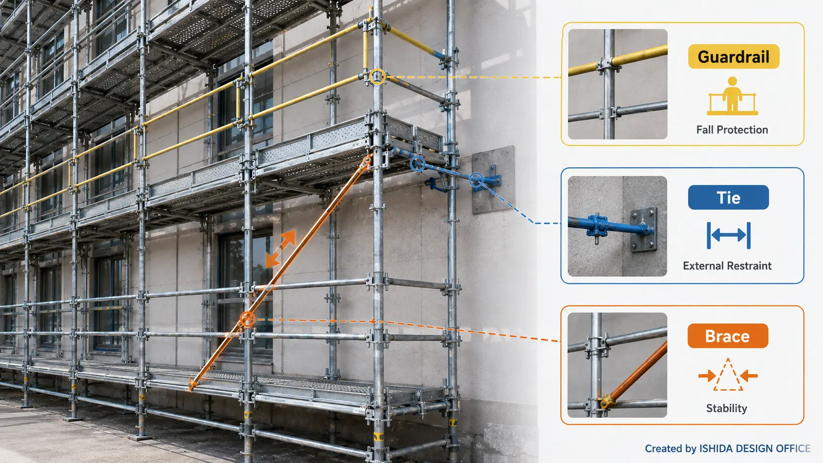
A brace, scaffold tie and guardrail can all appear to be simple members on a scaffold drawing, but their primary functions are different. Confusing them can create a serious gap between the drawing and the actual stability system.
A Brace
A brace primarily contributes to scaffold stiffness and stability.
A Scaffold Tie
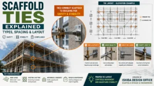
A scaffold tie connects or restrains the scaffold to a suitable permanent structure or other designed restraint. It provides something an internal diagonal brace does not automatically provide: external restraint.
A Guardrail
A guardrail primarily protects workers from falls.
It should not automatically be assumed to act as a structural brace.
Some proprietary systems use advance guardrail components that can perform more than one function. Where that structural role is specifically confirmed by the applicable system documentation, follow the manufacturer’s instructions.
For a broader practical overview of scaffold components and the checks associated with them, see Complete Scaffolding Parts Overview: Names, Functions and Practical Checks.
| Component | Primary Function | Structural Stability Role |
|---|---|---|
| Diagonal brace | Control deformation / stiffness | Yes, when designed for it |
| Scaffold tie | Restrain scaffold to structure | Yes |
| Guardrail | Fall protection | Not automatically |
| Approved proprietary advance guardrail | Fall protection | Only where the system allows |
| Raker | External stabilisation | Yes, when correctly designed |
Do not judge by appearance. Check the structural function.
How Bracing Works — Follow the Load Path
The best way to understand bracing is to stop thinking about one diagonal tube and start thinking about force. A reliable scaffold needs a continuous path that carries that force to something capable of resisting it.
Imagine a scaffold covered with sheeting.
Wind pushes against that sheeting.
What happens next?
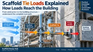
Wind → Sheeting → Scaffold Members → Bracing → Ties / Restraints → Permanent Structure
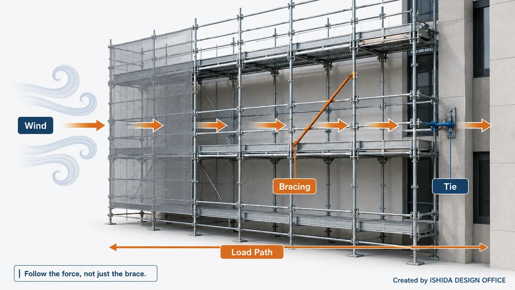
Every arrow matters.
A brace does not make the force disappear.
If the bracing is present but the restraint is inadequate, there may still be a stability problem.
If the ties are correctly positioned but the scaffold cannot transfer horizontal force toward them, there may still be a problem.
If both were correct on the drawing but a brace or tie has been moved on site, the intended load path may have changed.
One question I use repeatedly during drawing reviews is: “Where does the force go next?”
Bracing Is Not Just a Diagonal Tube
- Axial tension
- Axial compression
- Buckling effects
- Connection forces
- Eccentric effects
- Wind-induced forces
- Deformation and irregular geometry
This article explains design principles, not project-specific structural calculations. Where bespoke engineering is required, the braces, connections, ties, anchors and supporting structure should be considered as one stability system.
Scaffold Bracing Layout — How I Review It
A good bracing layout should form a clear and continuous stability system rather than a collection of isolated diagonals. When I review a drawing, I first look at the whole structure and then move into the details.
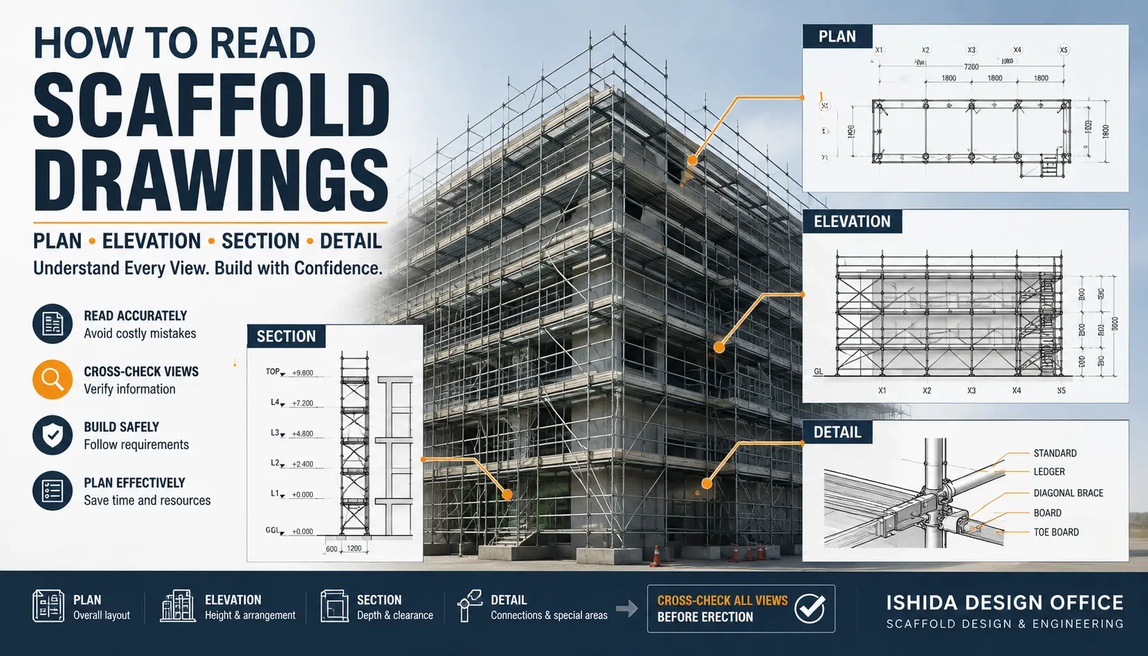
For a practical explanation of how plan, elevation, section and details should be read together, see How to Read Scaffold Drawings: Plan, Elevation, Section & Details.
I usually start zoomed out.
That gives me the overall logic before individual braces distract me.
Step 1 — Understand the Overall Geometry
- Total scaffold height and length
- Scaffold width
- Bay lengths and lift heights
- Returns and corners
- Setbacks and changes in level
- Entrances and access routes
- Loading bays and stair towers
- Bridges and cantilevers
- Mesh or sheeting
Bracing cannot be understood separately from scaffold geometry. For a deeper explanation, see Scaffold Dimensions Explained: Bay Length, Lift Height, Width & Standards.
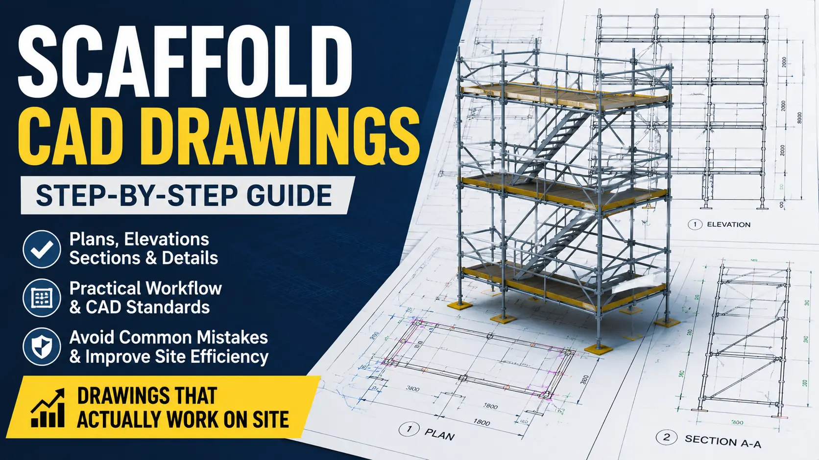
For the drawing-production side of this coordination process, see How to Create Scaffold CAD Drawings That Actually Work on Site.
Step 2 — Look for Continuity
- A diagonal that stops unexpectedly
- Large areas with no obvious bracing
- Sudden changes in the bracing pattern
- An entrance cutting through the intended brace line
- A stair tower interrupting the layout
- Tie positions that no longer match the intended stability arrangement
Step 3 — Check the Ends
The first and last bays deserve attention. Long repetitive elevations naturally draw the eye toward the middle, but end conditions can behave differently.
Step 4 — Check Corners and Returns
- How are the two elevations connected?
- Are standards shared or separate?
- How are ties arranged near the corner?
- Does bracing continue logically?
- Can the intended load path continue around the return?
Step 5 — Check Every Interruption
- Pedestrian and vehicle entrances
- Loading bays
- Stair towers and hoist openings
- Balconies
- Bridges and cantilevers
- Temporary roofs and protection fans
- Projecting canopies
These are often the exact locations where construction convenience and structural requirements collide.
A Practical CAD Review: Correcting Bracing in a Wedge-Lock Scaffold
In one of my scaffold design projects, I identified a problem with the diagonal bracing arrangement of a wedge-lock scaffold while reviewing the CAD drawings. Some braces were not positioned where they were required.
Rather than simply moving the diagonal members, I reviewed the bracing arrangement together with the wall ties and other reinforcing members. This led to changes in the positions of the braces and reinforcing members.
I also prepared structural strength calculations to verify the revised design. For me, a drawing is not complete simply because the arrangement looks practical. Its structural safety must be supported by appropriate engineering calculations.
My design decisions follow three priorities:
1. Compliance with applicable regulations. I first confirm that the proposed arrangement meets the legal and technical requirements applicable to the project.
2. Structural safety verified by calculations. I prepare strength calculations to evaluate the revised arrangement rather than relying on visual judgment alone.
3. Safe and efficient worker access. I also consider access routes and working space so that the scaffold can be used efficiently without compromising safety.
This experience reinforced an important lesson from my years of scaffold design work: correcting a misplaced brace is not simply a matter of moving a diagonal member on a CAD drawing. The revised arrangement must be considered as part of the complete scaffold stability system.
For me, good scaffold design means balancing regulatory compliance, verified structural safety and practical working conditions.
When an Opening Interrupts the Brace
Entrances and access routes are classic examples of practical conflicts with diagonal bracing. The solution is not simply to remove the brace; the structural function of that brace must first be understood.
Imagine that a building entrance is introduced exactly where a diagonal brace passes. Someone may understandably say, “We cannot leave that brace there.”
That may be true. But the next question must be:
What now performs the structural function of that brace?
A Better Decision Process
- Identify the conflict
- Review the structural function
- Design or verify an alternative arrangement
- Update the drawing or method statement where required
- Carry out the authorised alteration
- Inspect the completed arrangement
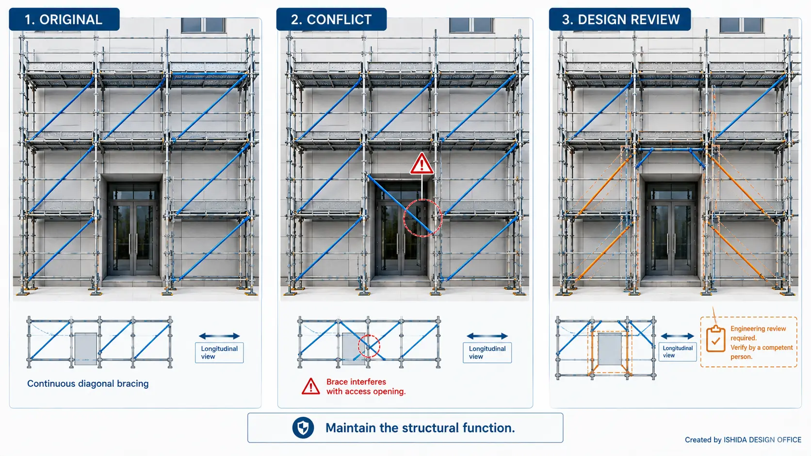
Possible solutions may involve relocated bracing, supplementary bracing, revised tie positions, proprietary components or another engineered load path. There is no universal answer.
Wind, Mesh and Sheeting Can Change Stability Demand
A scaffold designed as an open structure may behave very differently after mesh, sheeting or temporary enclosure is added. Visually, the modification may seem small; structurally, it may change the horizontal loading considerably.
This deserves particular attention on renovation work.
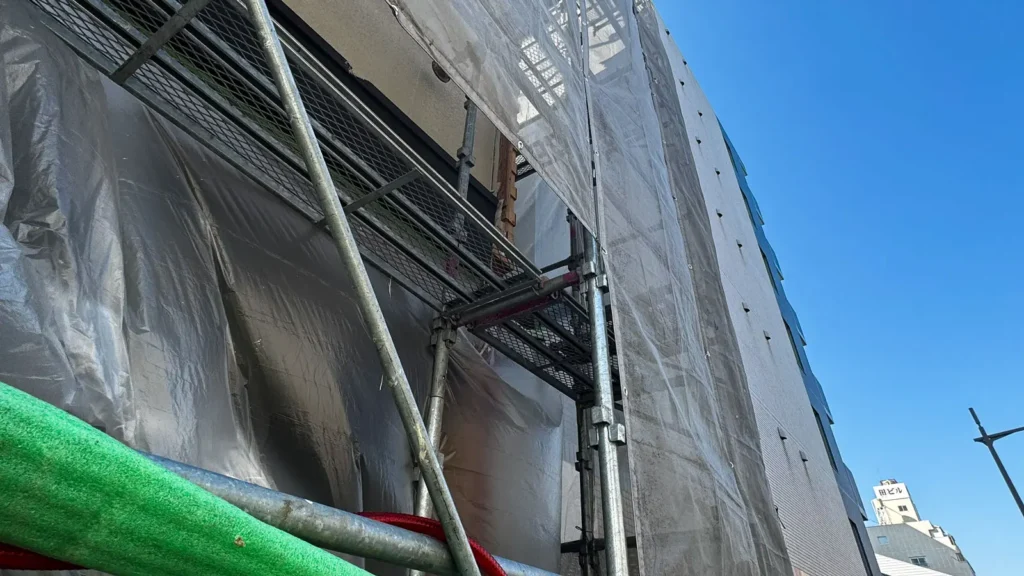
An open scaffold allows much of the wind to pass through.
Add a large enclosure and the situation changes.
Again, follow the force:
Wind → Enclosure → Scaffold → Bracing → Ties / Restraints
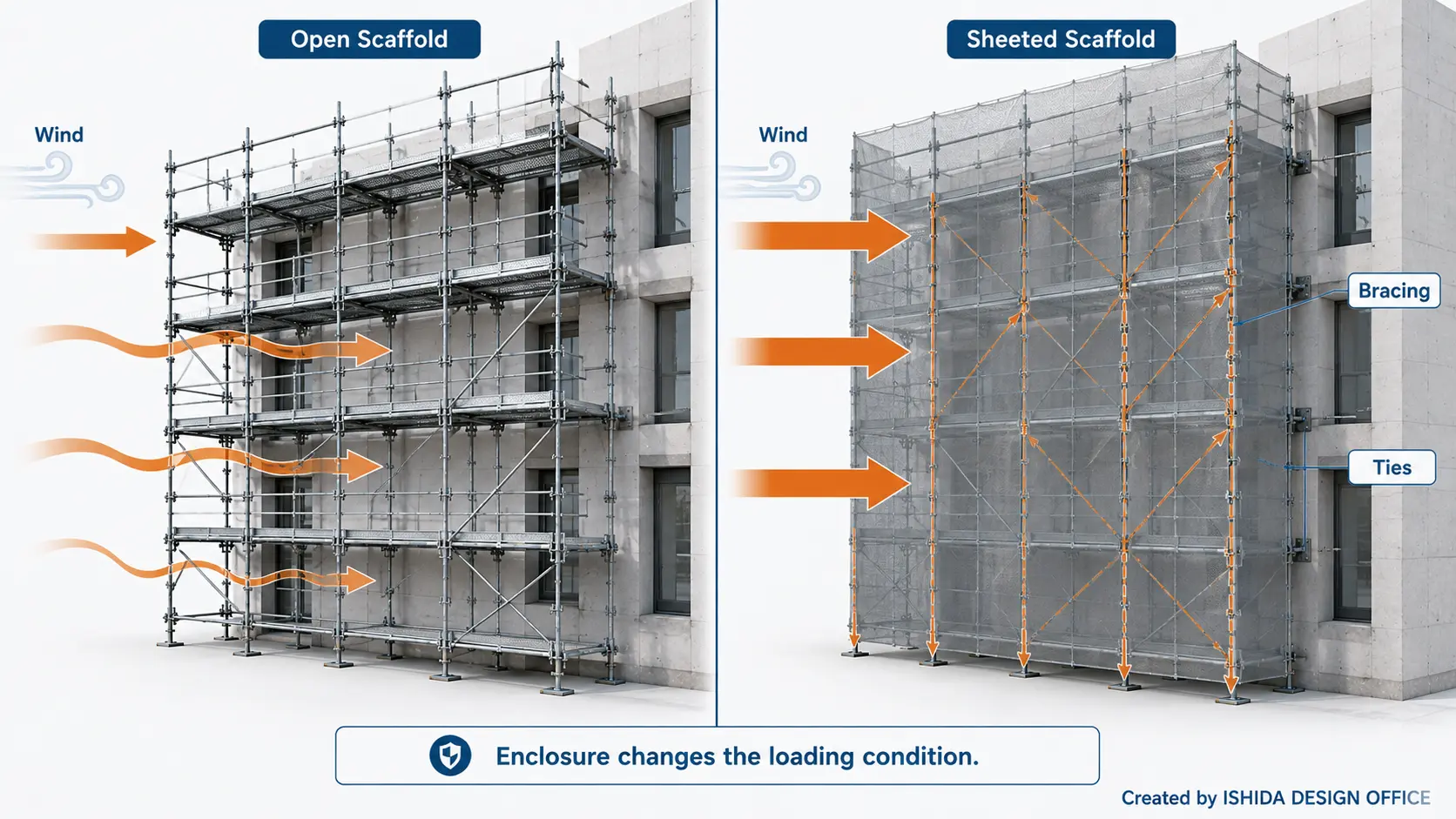
HSE includes sheeting, netting and brickguards among the information that should be considered during scaffold planning. When enclosure conditions change, the design may need to consider wind exposure, scaffold height, building geometry, material permeability, tie arrangement, anchor capacity, brace arrangement and supporting structure.
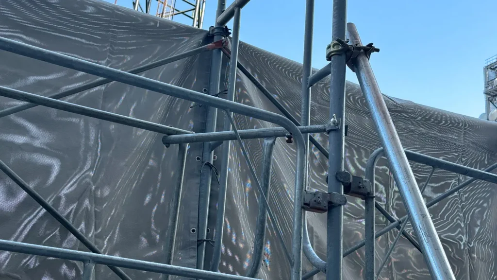
“It is only mesh” is not a design check. Confirm whether the installed condition matches the design assumptions.
Scaffold Bracing Design — A Practical Engineering Approach
A bracing layout should be developed as part of the complete scaffold stability system. Geometry, loading, ties, foundations, special structures and the scaffold system itself all influence the final arrangement.
Design Factors I Check
| Design Factor | Why It Matters |
|---|---|
| Scaffold height | Influences overall stability and wind exposure |
| Scaffold width | Influences geometric stability |
| Bay length | Changes structural geometry and bracing arrangement |
| Lift height | Changes scaffold geometry and brace configuration |
| Tie pattern | Determines external restraint |
| Wind exposure | Creates horizontal demand |
| Mesh / sheeting | Can increase wind effects |
| Loading bay | Introduces concentrated and eccentric effects |
| Cantilever | Can introduce overturning effects |
| Bridge / opening | Interrupts normal load paths |
| Foundation | Must safely receive reactions |
| Scaffold system | Determines component and connection behaviour |
| Erection sequence | Stability may differ before the scaffold is complete |
My Eight-Step Stability Review Sequence
1. Define the Geometry
Confirm height, length, width, bay sizes, lift heights, corners, openings and special sections.
2. Define the Scaffold System
Identify whether the scaffold is tube-and-fitting, frame scaffold, wedge-lock, ring-type modular scaffold or another proprietary system.
3. Identify the Loads
Consider self-weight, working loads, wind, sheeting, loading platforms and other relevant temporary loads.
4. Identify the Restraints
Identify ties, anchors, returns, rakers, buttresses, outriggers or other designed restraint systems.
5. Establish the Load Path
Ask where horizontal force enters, where it travels and where it is finally resisted.
6. Determine the Bracing Arrangement
Follow the manufacturer’s instructions, recognised configuration, applicable regulation or engineered scaffold design.
7. Check Interruptions
Review entrances, loading bays, stair towers, bridges, cantilevers, setbacks and changes in level.
8. Check Erection and Dismantling Stages
The completed scaffold may be stable while an intermediate erection stage behaves differently. Relevant temporary stages also need to be considered.
Japanese Practice Note
In Japanese scaffold practice, bracing is often considered together with scaffold type, bay arrangement, proprietary components and the way the scaffold must fit within a restricted construction site.
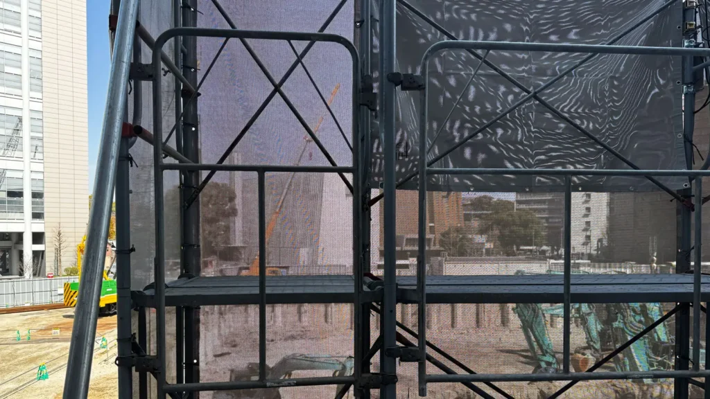
Japanese wedge-lock scaffolds may use dedicated diagonal members, steel-tube main bracing or approved advance-guardrail components depending on the recognised system configuration. In my Japanese technical work, what I consider most transferable internationally is not a particular spacing number. It is the checking habit.
During drawing reviews, I pay particular attention to small interruptions: an entrance, a narrow façade, a change in bay size, a loading point, a corner or a brace that no longer reaches the intended connection. I also prefer to coordinate bracing, ties, pedestrian movement, mesh and material access before erection starts rather than solve each conflict individually later on site.
The engineering principle can travel across borders even when the detailed rules cannot.
Requirements vary by country, jurisdiction and scaffold system. Always confirm local regulations, manufacturer instructions and the project-specific design before applying a Japanese arrangement elsewhere.
What Japanese Wedge-Lock Practice Can Teach International Readers
Japanese technical guidance provides a useful example of why bracing requirements must be understood in the context of the scaffold system. It is valuable as a comparison, but it should not be copied directly into projects governed by different systems or jurisdictions.
For certain Japanese wedge-lock arrangements, technical guidance is commonly expressed using braced zones within approximately six lifts by six bays. Different concepts may be used for tube-and-coupler arrangements, including approximately eight lifts by eight bays in some Japanese practice.
These are Japanese system-specific examples. They are not universal US, UK, Australian or international brace-spacing rules.
Advance Guardrails
Certain approved Japanese proprietary advance-guardrail arrangements can provide structural performance where that role is specifically recognised by the applicable system documentation. This does not mean that all guardrails are braces.
It means that a proprietary component may perform more than one function when its tested and approved system documentation confirms that function.
International Perspective on Scaffold Bracing
The regulatory details vary between the United States, United Kingdom, Australia, Japan and other jurisdictions. The common principles are similar: maintain stability, follow the approved configuration or design, use competent people and reassess the scaffold when significant changes occur.
United States — OSHA
OSHA 29 CFR 1926.451(c)(3) requires supported scaffold poles, legs, posts, frames and uprights to be plumb and braced to prevent swaying and displacement.
OSHA 1926.451(c)(1) also requires supported scaffolds exceeding a height-to-base-width ratio of 4:1 to be restrained from tipping by guying, tying, bracing or equivalent means, subject to the detailed provisions of the standard.
United Kingdom — HSE
HSE requires scaffolds to be adequately founded, braced and tied into a permanent structure or otherwise stabilised. Proprietary system scaffolds should be erected and tied according to the manufacturer’s instructions.
Where a scaffold falls outside a recognised standard configuration or applicable manufacturer guidance, bespoke design may be required.
Australia — Safe Work Australia
Safe Work Australia treats scaffold collapse as a major risk and emphasises appropriate control measures, inspection, maintenance and manufacturer or supplier instructions. State and territory requirements should also be checked for the actual project.
Different legal systems use different wording, but the common objective is the same: the scaffold must remain stable throughout erection, use, alteration and dismantling.
Manufacturer Instructions Matter More Than Generic Rules
A proprietary scaffold system is an engineered system, not simply a collection of steel members that happen to connect together. Brace locations, connections and standard configurations should therefore follow the applicable system documentation.
- Check manufacturer assembly instructions
- Confirm the recognised standard configuration
- Verify component compatibility
- Review project-specific scaffold design
- Confirm applicable local regulations
Components that physically fit together are not automatically structurally interchangeable.
10 Common Scaffold Bracing Mistakes
Most bracing problems are not exotic engineering problems. They are often ordinary coordination, installation and modification issues that become structural problems because the consequences were not reviewed.
For more lessons drawn from long-term scaffold design practice, see What 30 Years of Scaffold Design Has Taught Me.
1. A Brace Is Missing
Do not stop at “there should be another tube here.” Ask whether the installed scaffold still matches the approved design or recognised configuration.
2. The Brace Is Installed in the Wrong Bay
A scaffold may still look braced, but location matters. A convenient brace is not automatically equivalent to the intended brace.
3. A Brace Has Been Removed for Access
The reason may be understandable, but access convenience does not remove the structural function of the brace.
4. A Tie Was Removed but the Bracing Was Not Reconsidered
The diagonal braces may still be visible while the external restraint has changed. Always review ties and bracing together.
5. Mesh or Sheeting Was Added Later
The original scaffold may have been planned as an open scaffold. The enclosure can change the loading condition.
6. A Guardrail Is Assumed to Be a Brace
Do not assume structural equivalence unless the approved system or design confirms it.
7. Connections Are Loose or Incomplete
A brace can transfer force only through its connections. Check couplers, wedges, pins, locks and proprietary connection points.
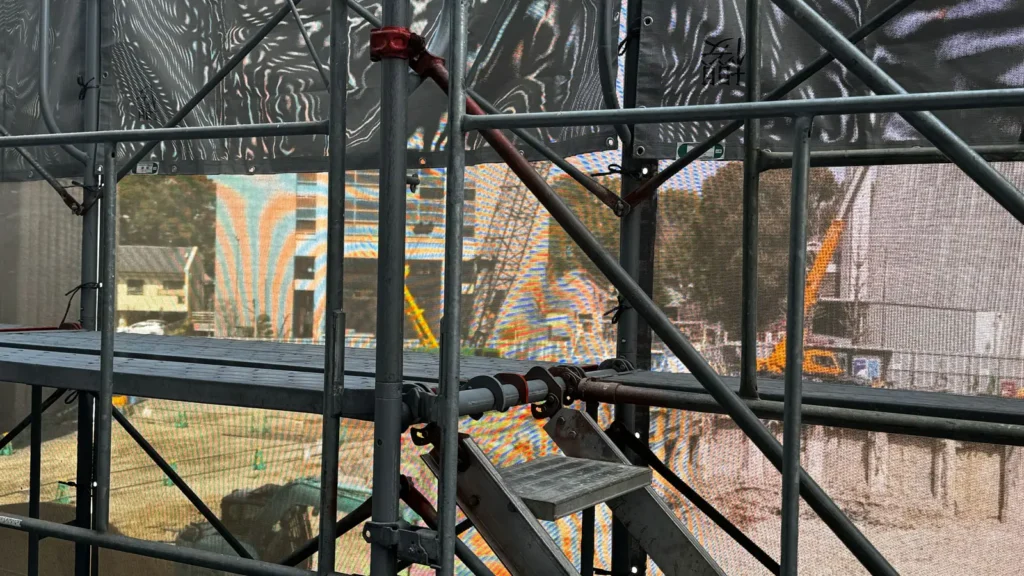
8. The Drawing Shows Bracing but the Site Does Not
A perfect CAD drawing cannot stabilise a scaffold that was erected differently.
9. Only the Elevation Is Checked
Bracing is three-dimensional. Review plan, elevation and section together where relevant.
10. “Add More Braces” Is Used as the Solution to Everything
More steel does not automatically mean better engineering.
Correct members + correct locations + correct connections + correct restraints + a continuous load path
Practical Scaffold Bracing Checklist
A checklist does not replace structural engineering judgement, but it is an effective way to catch ordinary omissions. I recommend checking the drawing first and then comparing the intended stability arrangement with the scaffold on site.
Drawing Review
- Scaffold system clearly identified
- Overall height and width confirmed
- Bay lengths and lift heights confirmed
- Bracing type and locations identified
- Bracing continuity checked
- End bays, corners and returns checked
- Tie layout reviewed together with bracing
- Entrances, stair towers and loading bays reviewed
- Bridges, cantilevers and plan bracing reviewed where applicable
- Mesh / sheeting condition identified
- Manufacturer requirements confirmed
- Non-standard areas identified for design review
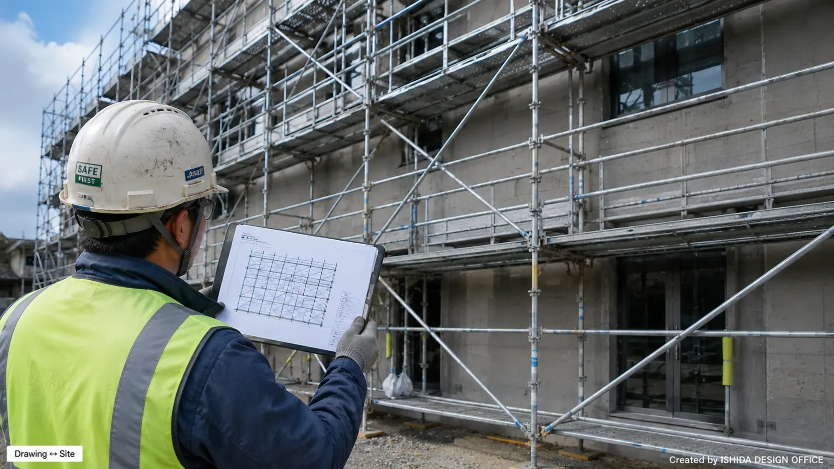
Site Review
- Correct brace type installed in the correct location
- Connections fully engaged
- No visibly damaged brace
- No unauthorised brace removal
- No unapproved substitute component
- Tie positions remain consistent with the stability arrangement
- Mesh / sheeting matches the design condition
- Special opening arrangements remain intact
- Significant changes have been reported
- Required inspection records are complete
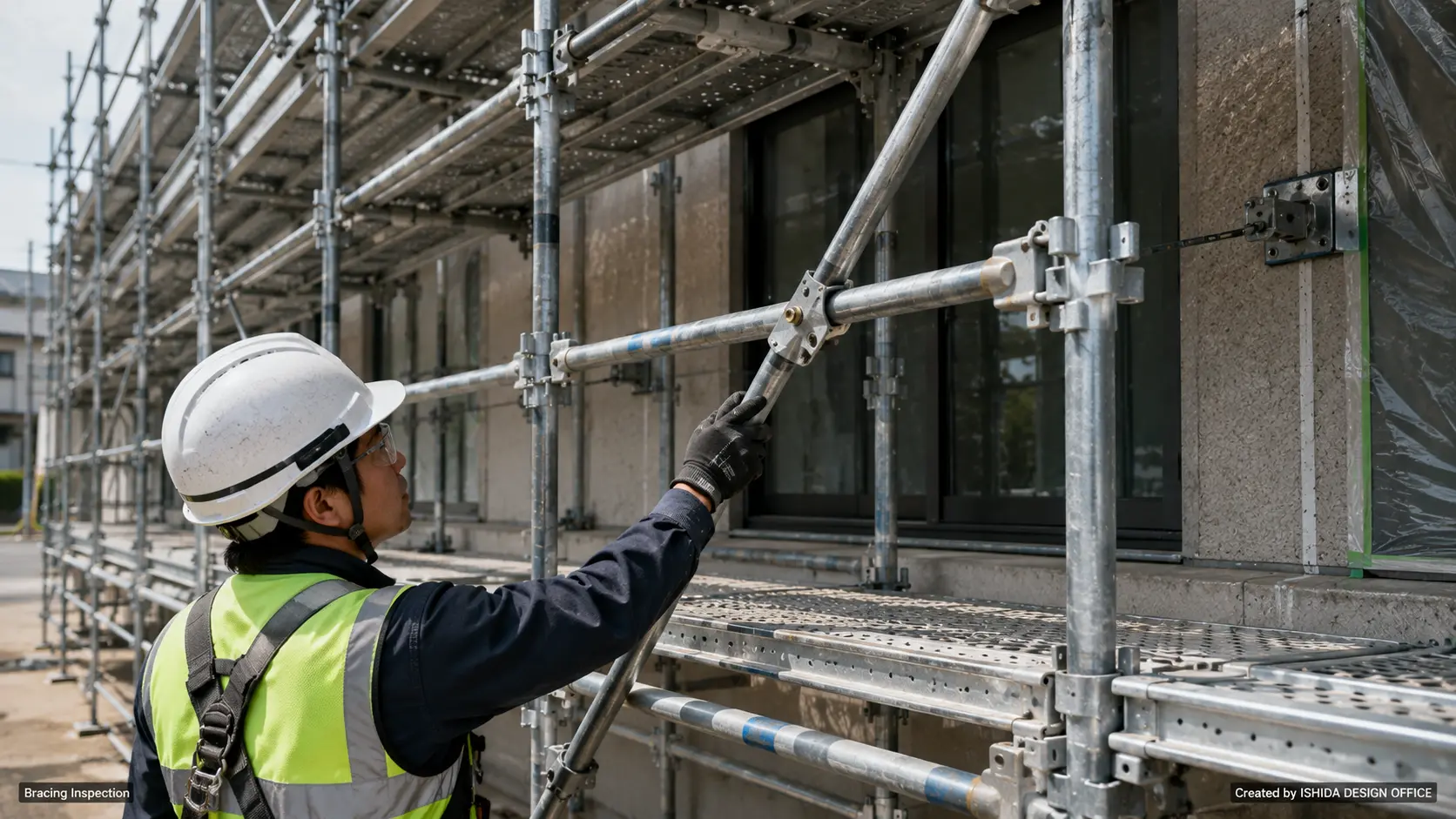
Does the scaffold on site still behave like the scaffold that was designed?
When Should Bracing and Stability Be Rechecked?
Inspection frequency is determined by the applicable jurisdiction, project requirements and scaffold system. However, several situations deserve particular attention.
Initial Erection or Handover
Confirm that the installed arrangement matches the approved drawing, recognised configuration or manufacturer instructions.
Before Use Where Required
Check that bracing, ties and connections remain complete before workers rely on the scaffold.
Required Periodic Inspections
Follow the inspection frequency required in the country, jurisdiction or project.
Significant Alteration
Recheck the stability arrangement when braces move, ties move, loading bays are added, entrances are enlarged, stair access changes or other structural components are altered.
Severe Weather
Wind can expose weaknesses or loosen components. Where regulations or project procedures require it, carry out the appropriate post-weather inspection.
Impact or Other Significant Event
If a vehicle, suspended load or another event could have affected structural integrity, the scaffold should be reassessed according to the applicable requirements.
In the United States, OSHA 1926.451(f)(3) requires scaffold components to be inspected for visible defects by a competent person before each work shift and after any occurrence that could affect structural integrity.
Example Scenario — An Entrance Breaks the Bracing Pattern
This is a hypothetical example scenario based on a common scaffold coordination problem. It is not presented as a specific client project or actual accident.
The Problem
A façade scaffold has a continuous bracing arrangement. During the project, a wider pedestrian entrance becomes necessary and the planned access route passes through one of the diagonal braces.
What Changed?
- Has longitudinal stiffness changed?
- Can the remaining bracing transfer the horizontal force?
- Does the tie arrangement still work?
- Does the opening require supplementary bracing?
- Has the scaffold moved outside the manufacturer’s recognised configuration?
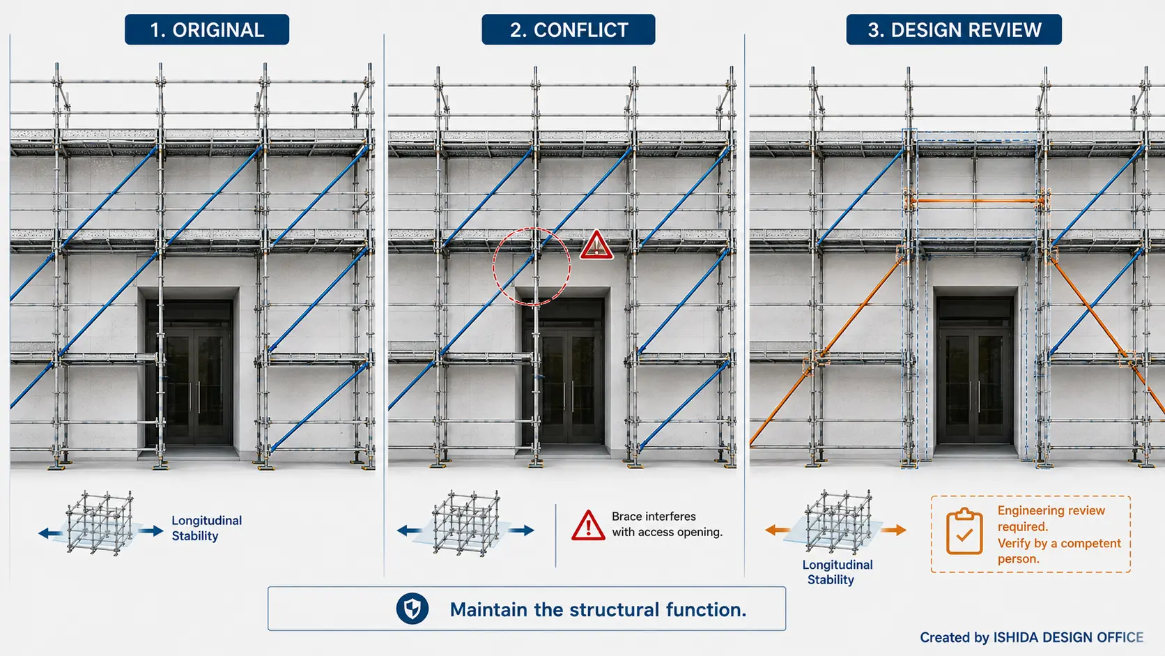
The Better Response
Raise the issue before alteration. A competent person or scaffold designer can then determine whether the correct solution involves relocated bracing, supplementary bracing, revised tie positions, a special opening detail or another engineered arrangement.
Result
Access is maintained.
The structural purpose of the original brace is not forgotten.
And everyone understands why the revised arrangement is there.
The Lesson
Never remove a structural function without replacing or reassessing it.
The lesson is not simply “Never move a brace.” There are situations where braces have to be relocated. The important point is that the stability function must be understood and maintained.
Real Project Experience: When Scaffold Bracing Blocks a Building Entrance
In my scaffold design work in Japan, I have encountered situations where a scaffold layout appeared correct on the CAD drawings but created an unexpected problem during installation.
In one case, I prepared the scaffold plan and elevation drawings based on the architectural design documents. The scaffold bays were carefully arranged, and the elevation drawing was completed using the planned building dimensions.
However, when the scaffold was erected, a diagonal brace at the first level obstructed a building entrance. People could no longer pass through the opening as intended.
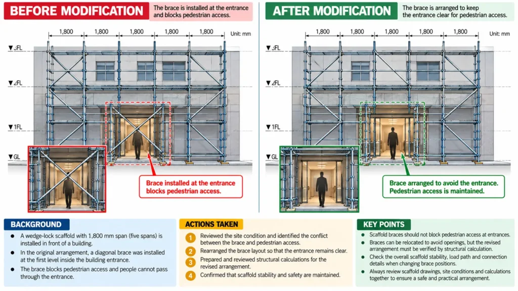
Why did the planned scaffold layout differ from the actual installation?
From my experience, there are three important reasons why this type of interference can occur.
1. The scaffold layout started from an unsuitable reference point.
The starting position of the scaffold bay arrangement is important. If the initial reference point is not properly selected, the position of the scaffold standards may gradually shift relative to the building openings as the layout progresses.
With repeated 1,800 mm bays, even a relatively small difference in the starting position can result in a significant conflict at an entrance farther along the façade.
2. The actual entrance position differed from the architectural drawings.
Sometimes the location of a building entrance or opening is changed after the original design drawings have been prepared.
If the scaffold layout is based only on those drawings without checking the latest site conditions, a brace may be positioned directly in front of an entrance that was expected to remain clear.
3. Unexpected site obstructions forced changes to the scaffold arrangement.
During scaffold installation, workers may encounter obstacles that were not shown on the original design drawings.
To avoid these obstacles, the scaffold bay arrangement may be adjusted on site. However, moving the standards or changing the bay arrangement can also change the relationship between the diagonal braces and the building openings.
A modification intended to solve one problem can therefore create another problem elsewhere.
Before and After: Revising the Bracing Arrangement
The accompanying illustration explains this type of problem using a five-bay wedge-lock scaffold with a nominal bay spacing of 1,800 mm.
Before Modification — Left Drawing
The diagonal brace at the first level crosses the building entrance and prevents normal pedestrian access.
Although the scaffold arrangement may have been prepared from the original design documents, the brace position is not practical for the actual entrance location.
After Modification — Right Drawing
The bracing arrangement is revised so that the entrance remains unobstructed.
Depending on the scaffold system, site conditions and structural requirements, possible solutions may include relocating the brace to a suitable adjacent bay or arranging the bracing at a higher level.
However, moving a brace is not simply a drawing adjustment. Changing the bracing arrangement may affect the scaffold’s lateral stability, load transfer and connections.
The revised arrangement must therefore be evaluated through appropriate structural design and calculations before it is accepted for construction.
What This Experience Taught Me
This experience reinforced an important lesson in my scaffold design work: an accurately prepared CAD drawing does not necessarily guarantee that the scaffold arrangement will work on site.
Architectural drawings, actual building dimensions, entrance locations, unexpected obstructions and the scaffold installation sequence must all be considered together.
When a diagonal brace conflicts with a building entrance, the solution is not simply to remove it or move it to a convenient location.
The revised bracing layout must be checked against the structural requirements of the scaffold, including its overall stability, load path, member capacity and connection details.
For this reason, I consider the review of actual site conditions and structural calculations to be essential parts of practical scaffold design.
Engineering note: The illustration is a simplified explanation of the interference and possible modification. It does not represent a universally approved bracing arrangement. Any revised configuration requires project-specific structural verification.
Frequently Asked Questions About Scaffold Bracing
What is the main purpose of scaffold bracing?
Scaffold bracing contributes to stiffness and stability. It can help control racking, sway and unwanted displacement and form part of the load path for horizontal forces.
Is scaffold bracing the same as scaffold ties?
No. Bracing helps stabilise the scaffold structure, while ties generally provide external restraint by connecting the scaffold to a suitable structure or anchorage.
Can a guardrail replace a diagonal brace?
Not automatically. Treat a proprietary advance guardrail as part of the structural stability system only where the applicable manufacturer documentation, certification or engineered design specifically permits that function.
How often should diagonal braces be installed?
There is no single worldwide spacing rule. Brace spacing and arrangement depend on scaffold type, manufacturer, dimensions, loading, ties, wind exposure, enclosure, recognised configuration and project-specific engineering.
Can I temporarily remove a brace for access?
Do not remove a structural brace without first assessing how scaffold stability will be maintained. Alternative bracing, revised ties or another engineered solution may be required.
Does scaffold sheeting affect bracing requirements?
Potentially, yes. Sheeting, mesh and similar enclosures can change wind loading and may affect braces, ties, anchors and other parts of the stability system.
Does adding more diagonal braces always make a scaffold safer?
No. Adding random members does not correct an unidentified structural problem. More steel is not a substitute for a correct load path and verified engineering.
Related Topics
Bracing becomes easier to understand when it is connected with scaffold geometry, drawings and component functions.
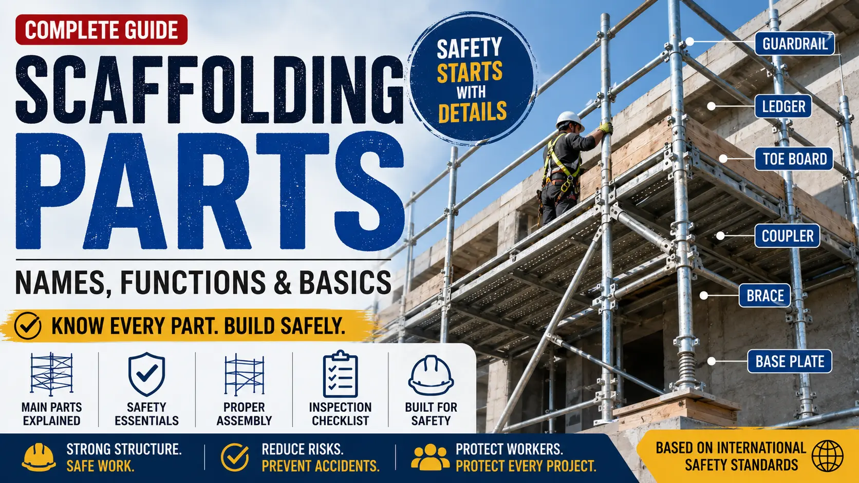
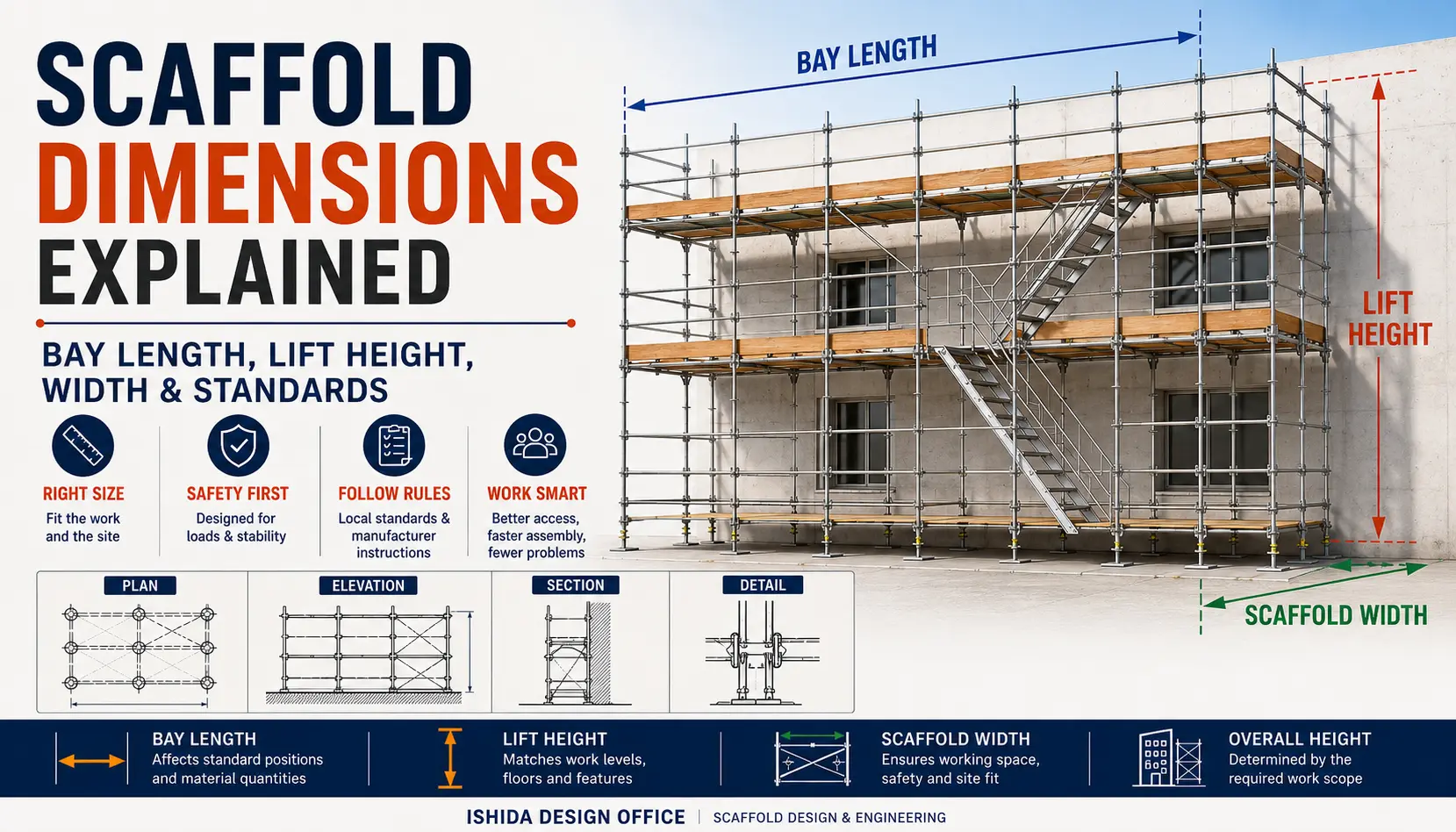
Parts → Dimensions → Drawings → Stability
Key Takeaways
- Bracing is about structural stability, not appearance.
- Follow the load path. Ask where horizontal force enters, where it travels and where it is finally resisted.
- A brace and a tie are not the same thing. They often work together, but their structural roles differ.
- Openings and alterations deserve special attention. Entrances, loading bays, stairs, mesh, sheeting and removed ties can change the stability system.
- Never copy a bracing rule blindly. Apply the requirements for the actual scaffold system, project and jurisdiction.
Conclusion
Scaffold bracing can look simple on a drawing—just a diagonal line. But behind that line is a much more important question:
How does this scaffold stay stable when something tries to move it?
After more than 30 years working with scaffold and temporary-works drawings, I still believe the best approach is to keep asking simple questions.
- What does this member do?
- Where does the force go?
- What has changed from the original drawing?
- Does the scaffold on site still behave like the scaffold we intended to build?
Those questions can help prevent avoidable rework, unnecessary cost and safety problems.
I hope this article helps you look at your next scaffold drawing with a little more confidence.
Keep checking the details. Keep asking good questions. And keep learning from every scaffold you see.
References
Official Government and Regulatory Sources
- Occupational Safety and Health Administration (OSHA) — 29 CFR 1926.451: General Requirements
U.S. scaffold requirements covering design, stability, tipping restraint, inspection and component compatibility.
OSHA — 29 CFR 1926.451 - Occupational Safety and Health Administration (OSHA) — 29 CFR 1926 Subpart L: Scaffolds
U.S. construction safety requirements for scaffolds.
OSHA — 29 CFR 1926 Subpart L - Health and Safety Executive (HSE) — Scaffolds
UK guidance covering scaffold planning, stability, bracing, ties, recognised configurations and bespoke design.
HSE — Scaffolds - Safe Work Australia — Scaffolds and Scaffolding Work General Guide
Guidance on scaffold planning, risk management, erection, alteration, dismantling, inspection and safe use.
Safe Work Australia — General Guide - Scaffolding and Construction Equipment Association of Japan
Japanese technical information for scaffold systems and recognised construction practices.
Scaffolding and Construction Equipment Association of Japan
Manufacturer Technical Information
- PERI — Scaffolding Systems / PERI UP
Manufacturer information for modular scaffolding systems, components and applications.
PERI — Scaffolding Systems - Layher — Scaffolding Systems
Manufacturer information for proprietary scaffold systems and technical applications.
Layher — Official Website
Reference Verification
Last Updated: September 26, 2026
All external references and official guidance listed above were checked at the time of writing.
Regulations, manufacturer manuals and industry guidance can change. Readers should confirm the latest requirements through the official sources before applying technical information to a live project.
Where state, territory or local requirements apply, consult the relevant regulator.
Safety Disclaimer
This article is intended for general educational purposes.
It is not a substitute for project-specific scaffold design, engineering calculations, competent-person assessment, approved method statements, manufacturer documentation or applicable legal requirements.
Requirements vary by country, jurisdiction and project.
Always follow local laws, project specifications, approved design information and the scaffold manufacturer’s instructions.
Where the correct requirement is uncertain, consult the official guidance and an appropriately competent or qualified person.
Related Articles
Last Verified
Last Verified: September 2026
Regulations, official guidance and manufacturer documentation may change. Always confirm the current requirements applicable to the project location, scaffold system and intended use.
This article is general technical information and is not a substitute for project-specific engineering, applicable law, contract documents, project specifications, manufacturer instructions or competent professional review.
About the Author
ISHIDA DESIGN OFFICE brings more than 30 years of practical experience in Japan, specializing in scaffolding design, temporary works planning, CAD drafting, quantity estimation, and construction support.
Drawing on experience from residential, commercial, and industrial projects, he shares practical insights that emphasize not only sound engineering design but also buildability, safety, and real-world jobsite application.
At Scaffold Design Hub, he combines practical experience from Japan with official guidance and technical resources from government agencies, manufacturers, and industry organizations around the world to provide reliable, practical information for construction professionals.
To learn more, visit the About page. For questions or project inquiries, please use the Contact page.