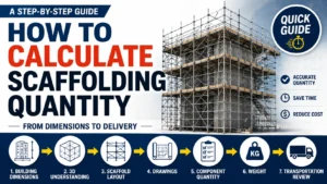

Estimating scaffold materials from drawings is not simply a matter of multiplying scaffold length by height. A dependable material takeoff must translate the actual arrangement shown in the plan, elevations, sections and details into component quantities, then check the repeated areas against every exception.
The practical sequence is:
Drawing scope → scaffold geometry → repeated bays and lifts →
component groups → exceptions → cross-check → material
schedule
This article explains that framework without prescribing a universal formula. Component names, available sizes, capacities and permitted configurations differ between scaffold systems, manufacturers, projects and jurisdictions. Always use the drawings, project requirements and current manufacturer information that apply to the scaffold being estimated.
The Short Answer
To estimate scaffold materials from drawings:
- Confirm the drawing revision, scaffold system, scope and design assumptions.
- Read the plan to identify scaffold runs, bay divisions, returns, corners, access bays and changes in width.
- Read each elevation to identify lift levels, platformed lifts, top protection, braces, ties and height changes.
- Use sections and details to confirm scaffold width, standards, working-platform arrangement, inner protection and interfaces with the building.
- Count repeated standard zones separately from irregular or non-standard zones.
- Record quantities by component type and size in a controlled material schedule.
- Cross-check the schedule against all views, detail references, revisions and manufacturer requirements.
- Keep the exact drawing quantity separate from any additional quantity allowed for logistics, replacement or site operations.
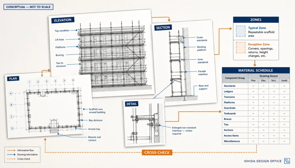
The important distinction is this: count the scaffold configuration shown in the drawings, not just the rectangular area around the building.
Why Scaffold Area Alone Is Not Enough
Scaffold area can be useful for early budgeting, broad comparisons or a preliminary sense of scale. It is not a complete material takeoff.
Two scaffolds with the same nominal elevation area can require different quantities because their geometry and use are different. One may have long repeated bays; the other may include short returns, recessed walls, balconies, entrances, access towers, loading areas and several changes in height. Their areas may look similar, but their standards, ledgers, guardrails, platforms, ties and special components will not necessarily match.
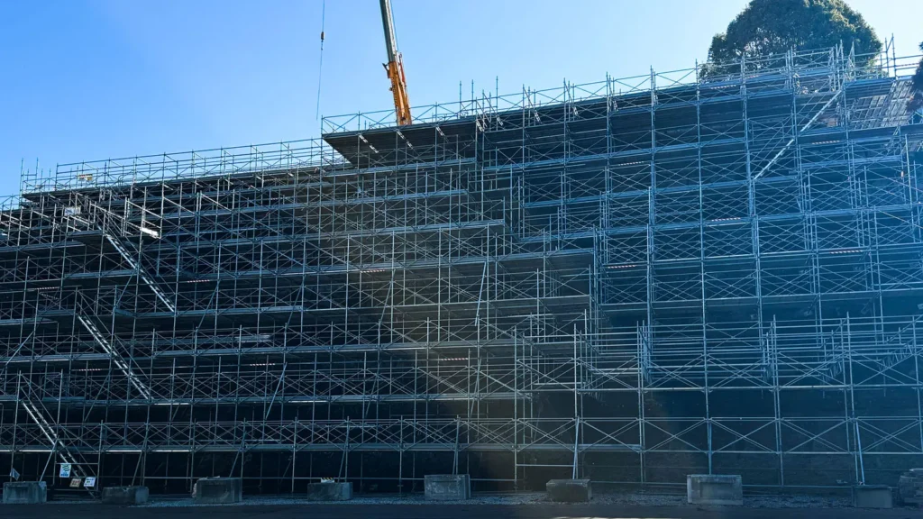
Area-based shortcuts also tend to conceal components that do not follow the same repetition as the main frame. Ties follow an approved layout and real attachment locations. Bracing may be interrupted or relocated around access routes and openings. Inner guardrails depend on the gap and fall risk at the building side. The uppermost lift may require a different arrangement from the typical lifts below.
In my work on scaffold drawings since 1998, I have found that a simple area calculation can lead to avoidable material takeoff errors when it replaces a drawing-by-drawing review. I pay particular attention to outer and inner guardrails, the actual number of ties, whether the top height has been reflected correctly, and areas where a system scaffold does not fit the building geometry in a standard repetition.
That is a practical observation, not a universal calculation rule. The correct takeoff still depends on the specific system, drawings, manufacturer instructions, erection method and site conditions.
What You Need Before Starting the Takeoff
A takeoff should not begin from an isolated elevation image if the underlying scope is unclear. Collect and confirm the controlling information first.
At minimum, review:
- the current drawing register and revision status;
- plans, elevations, sections and referenced details;
- scaffold type and manufacturer or system information;
- intended use and load requirements;
- platformed lifts and access arrangements;
- sheeting, netting, brick guards or other attachments;
- tie layout and any restrictions on tie locations;
- loading bays, hoists, fans, bridges, cantilevers or other special structures;
- ground, slab or support conditions where they affect base components;
- phased erection, alteration or dismantling requirements; and
- exclusions, temporary removals or items supplied by others.
If these inputs conflict, record the discrepancy instead of silently choosing the most convenient drawing. A material estimate built on an unresolved design conflict can look precise while still being wrong.
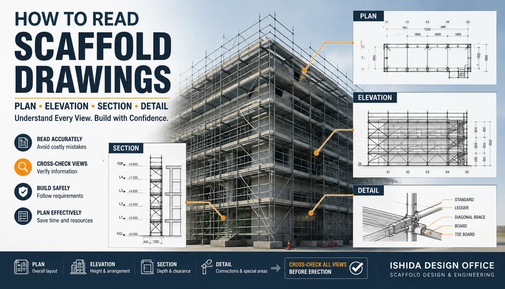
For readers who need a foundation in drawing interpretation, see How to Read Scaffold Drawings: Plan, Elevation, Section & Details and Scaffold Plan vs Elevation vs Section: What Each Drawing Shows.
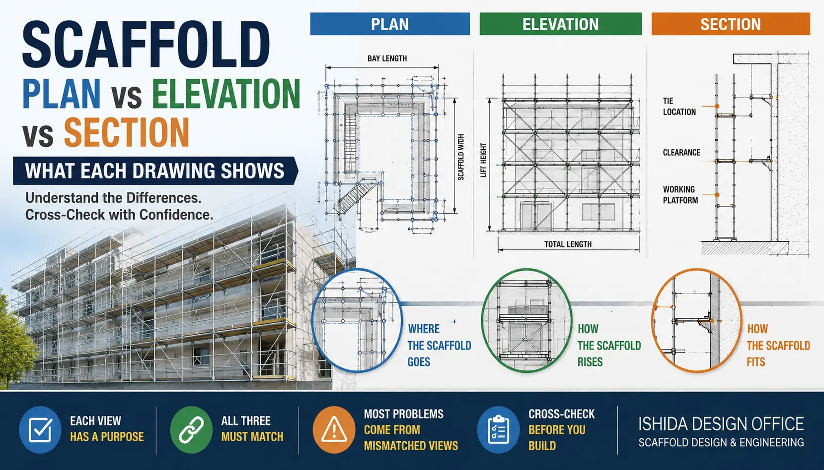
Which Drawing Controls Which Quantities?
No single view controls the complete takeoff.
| Drawing or document | What it usually reveals | Typical quantity decisions |
|---|---|---|
| Plan | Scaffold runs, bay divisions, corners, returns, offsets, access bays and footprint constraints | Horizontal members, standards per line, decks per bay, corner and return components |
| Elevation | Lift levels, overall height, platformed lifts, top arrangement, braces, ties and discontinuities | Vertical members, lift-by-lift ledgers, guardrails, toe boards, braces and ties |
| Section | Scaffold width, inner/outer standards, facade clearance, brackets, platform arrangement and projections | Transverse components, decks across the width, inner protection and special interfaces |
| Detail | Non-standard junctions, bridges, openings, cantilevers, support changes and local solutions | Special parts and adjustments not captured by a typical-zone count |
| Notes and schedules | System, component sizes, load class, restrictions, specifications and revision information | Correct component family, sizes, ratings and scope boundaries |
The table is a review guide, not a hierarchy that allows one drawing to override another automatically. The views must agree. If they do not, the discrepancy needs clarification.
A Practical Drawing-Based Estimation Framework
Confirm the Scaffold Scope and System
Start with the boundary of the estimate. Does it cover the complete building, one elevation, one phase or only a modification? Are stairs, loading bays, debris netting, fans and hoists included? Are transport frames, storage racks or erection consumables part of the requested list?
Then confirm the scaffold system. A generic label such as “system scaffold” is not enough to select exact components. Product families use different node spacing, bay sizes, deck widths, connection methods and accessories. The estimate must use the approved component data for the intended system.
If component terminology is unfamiliar, Complete Scaffolding Parts Overview: Names, Functions and Practical Checks provides a useful orientation. Do not use a general parts guide as a substitute for the relevant manufacturer’s documentation.

Read the Plan as Horizontal Geometry
Break the plan into identifiable scaffold runs. Record each change of direction, bay length, width, offset and termination. Treat corners and returns deliberately: the end of one run may share geometry with the start of another, so uncontrolled counting can either duplicate or omit components.
Mark elements that interrupt the normal rhythm, including entrances, vehicle routes, stairs, ladder bays, recesses, projections and narrow spaces. If a bay changes size, record that size rather than averaging it into the main run.
A useful plan review asks:
- How many continuous runs are there?
- Where does the bay pattern change?
- Which standards are shared at adjacent bays?
- Where does the scaffold turn, step, stop or restart?
- Are there inner and outer standard lines throughout?
- Which plan areas refer to separate details?
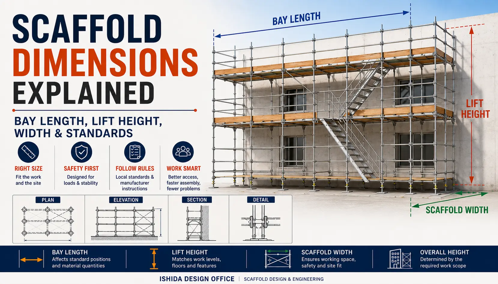
For a deeper explanation of bay length and scaffold width, see Scaffold Dimensions Explained: Bay Length, Lift Height, Width & Standards.
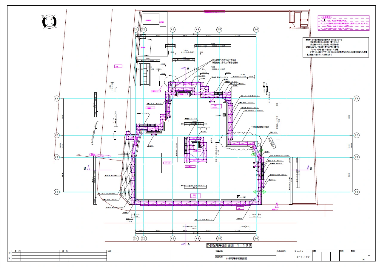
How I use CAD for material takeoff: In my scaffold drawing work, I use the estimation-support functions in my CAD software to help prepare material quantities. I then check the results against the drawings rather than relying on the software output alone. One method I avoid is making a rough material estimate from the overall drawing area. In my experience, that approach often leads to repeated corrections and rework because it does not adequately reflect the actual scaffold arrangement.
Read the Elevations as Vertical Geometry
The elevation converts each plan run into lift-by-lift quantities. Identify the base level, lift heights, working platforms, non-boarded lifts, top lift, guardrail extension and every change in scaffold height.
Do not assume that all elevations have the same number of lifts. Sloping ground, stepped roofs, setbacks and different facade heights can change the vertical arrangement. Also check whether a lift continues across an opening or is interrupted by a bridge, loading bay or access feature.
The elevation is normally the clearest place to review face bracing and tie symbols, but their quantities should be checked against plan positions and details. A symbol repeated graphically is not enough if the attachment point or local configuration is not defined.
Use Sections to Define Width and Interfaces
Sections answer questions that a flat elevation cannot. They show how many standards form the scaffold width, how the platform is supported, the working gap to the facade, and whether brackets or inner platforms are used.
They are also essential when deciding whether inner guardrails, toe boards or other protection are included. Never copy the outer guardrail quantity to the inner face automatically. Review the building-side condition at each relevant level and use the approved design and local requirements.
Sections through balconies, roofs, canopies and changes in facade line should be reviewed separately from a typical wall section. These interfaces frequently generate components that disappear in an area-only estimate.
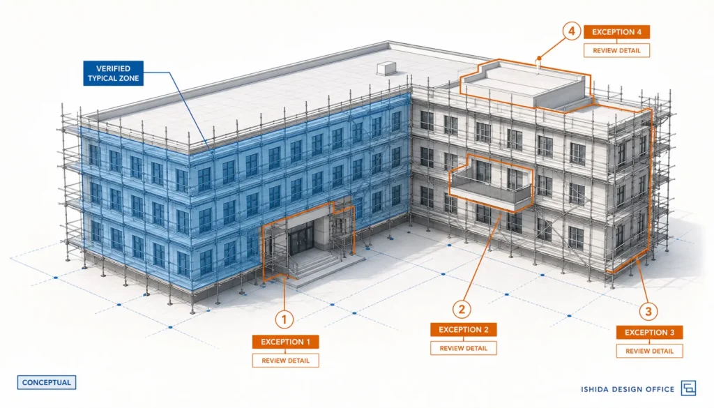
Separate Repeated Areas from Exceptions
Efficient takeoffs use repetition, but only after the repeated unit has been verified. Define a typical zone—for example, a continuous group of equal bays with the same lift arrangement, platform configuration and protection—and count it consistently.
Then create an exception register. Typical exception zones include:
- corners and short returns;
- ends and termination bays;
- recessed or projecting facades;
- doorways and vehicle access;
- balconies, canopies and roof interfaces;
- stair or ladder access bays;
- loading bays, hoists and rubbish chutes;
- bridges, beams, fans and cantilevers;
- changes in ground or support level;
- changes in scaffold width or platform arrangement; and
- locations outside the standard system configuration.
Build the Component Schedule
Record components by exact description and size. A schedule that lists only “standards” or “decks” may not be sufficient for ordering or allocation when several lengths or types appear on the same project.
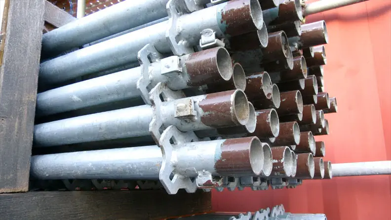
A practical schedule can include:
| Field | Purpose |
|---|---|
| Component group | Standards, ledgers, decks, guardrails, ties, braces, access, bases and accessories |
| System description or item code | Prevents ambiguity between similar components |
| Size or type | Separates lengths, widths, duties or configurations |
| Drawing source | Identifies the plan, elevation, section or detail supporting the quantity |
| Zone or elevation | Makes reconciliation and revision updates easier |
| Exact drawing quantity | Preserves the auditable takeoff result |
| Site-allocation adjustment | Kept separate and justified under project procedures |
| Notes or exclusions | Records assumptions, temporary items and unresolved points |
Do not hide an allowance inside the exact count. Separate fields make the estimate easier to review and revise.
What I Personally Check Before Accepting the Material Schedule
After preparing scaffold quantities from the drawings, I do not treat the material schedule as complete simply because the CAD software has produced a list. Based on my scaffold drawing work in Japan since 1998, I check four specific points before using the quantities for further planning. These are practical reconciliation checks, not a substitute for the approved design or manufacturer requirements.
1. Standard Types and Quantities
I first review the types, lengths and quantities of standards. A plausible overall total does not mean the breakdown is correct: standards of different lengths cannot automatically be treated as interchangeable. I compare the listed types with the lift heights, base conditions and top-of-scaffold arrangement shown in the drawings, and check that changes in height have been reflected in the component schedule.
2. Working Platform Quantities
Next, I check the number and type of working platforms against the planned platformed lifts and scaffold width. I pay particular attention to areas where the platform arrangement changes, such as access locations, returns or partial working levels. Multiplying a typical platform count across every lift can overlook these differences.
3. Wall Tie Quantities
I then compare the wall tie quantity with the tie locations indicated in the approved scaffold drawings. Openings, projections and restrictions on attachment locations can interrupt a regular pattern. I do not rely on an assumed tie spacing or scaffold area alone to determine the final count; unresolved tie locations require design clarification.
4. Consistency Between the Drawings and the Schedule
Finally, I reconcile the material schedule with the plan, elevations, sections and relevant details, using the current drawing revision. I look for components missing from irregular areas, differences between the drawing and the listed sizes, and possible double-counting where scaffold runs meet. If the schedule and drawings disagree, I return to the relevant drawing rather than adjusting the quantity without a clear basis.
My practical approach: A scaffold material schedule is not just a set of numbers generated from a model or a drawing. It must represent the scaffold that is actually planned. These four checks help me find discrepancies while the quantities can still be reviewed and corrected.
How to Review the Main Component Groups
Standards, Ledgers and Transoms
Standards are driven by the plan grid and the vertical segmentation of the selected system. Check shared standards at adjacent bays, separate inner and outer lines, changes in base level and any extension above the highest working platform.
Ledgers and transoms depend on more than the number of bays. Their level, size, direction and function must match the drawings and system configuration. Bridge zones, loading bays and changes in width may use arrangements different from the typical scaffold.
Platforms, Decks and Toe Boards
Identify which lifts are fully platformed, partly platformed or not intended as working platforms. Count the platform arrangement shown across the scaffold width; do not assume that every lift has identical decking.
Then review platform ends, returns, trapdoors, access openings and local gaps. Toe boards and related edge-protection parts follow exposed platform edges and project requirements, not simply the gross elevation area.
Outer and Inner Guardrails
Outer guardrails are usually visible on elevations, but their continuity can change at stairs, loading points, gates and platform transitions. End guardrails also need a separate check.
Inner guardrails require deliberate review. Their necessity and extent depend on the building-side gap, facade condition, working arrangement, local rules and approved design. A takeoff that counts only the obvious outer face can materially understate the required protection; copying the full outer quantity to the inside can also overstate it.
The correct question is not “How many guardrails are normally used?” It is “Which edges require protection in this specific approved scaffold arrangement?”
Bracing
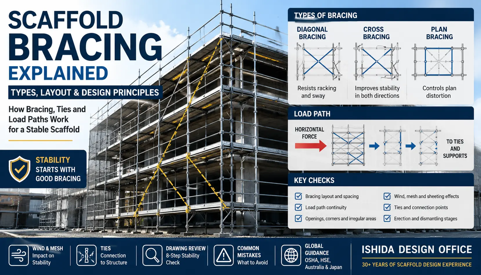
Count bracing from its documented layout and distinguish face bracing, transverse bracing and plan bracing where applicable. Check start and end points, orientation, interrupted runs and special bays.
Openings or access routes may affect where a brace can physically be installed. They do not justify omitting or relocating it without design review. For the underlying principles, see Scaffold Bracing Explained: Types, Layout & Design Principles.
Ties and Other Restraints
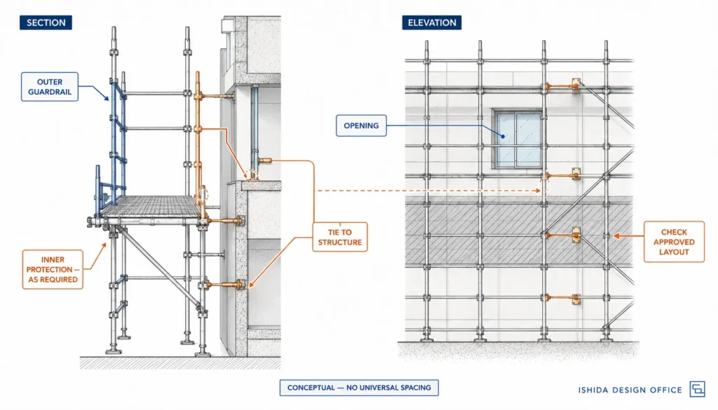
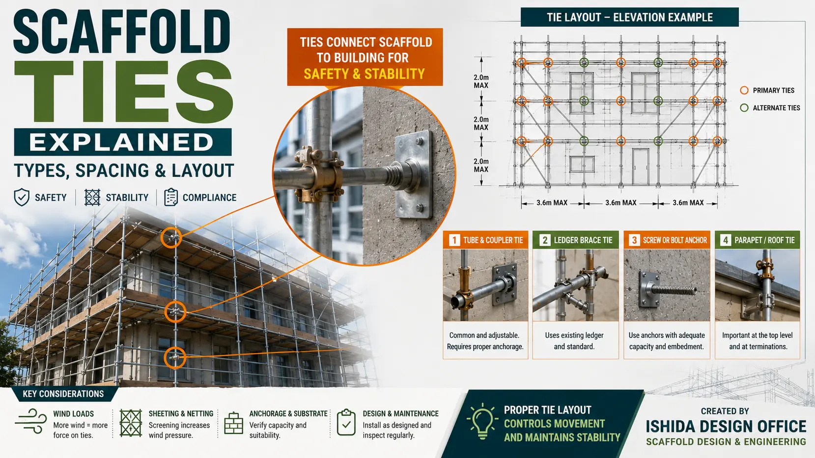
Ties must be counted from the actual approved layout, including any different tie types or duties. Do not estimate them solely from scaffold area or a generic spacing assumption.
Cross-check every tie symbol against the elevation, plan, building interface and relevant detail. Openings, balconies, cladding work and restricted attachment zones can disrupt a regular pattern. The estimate should reflect the resolved design rather than an idealized grid.
HSE states that proprietary system scaffolds should be erected and tied according to manufacturer instructions, and that design information should identify matters such as maximum tie spacing and tie duty. OSHA requirements for supported scaffolds are jurisdiction-specific and also address the locations and vertical repetition of guys, ties and braces. Use the rule set that applies to the project; do not combine values from different jurisdictions.
For a focused explanation, see Scaffold Ties Explained: Types, Spacing & Layout.
Access Components
Access is a component group, not a note to add at the end. Review staircase flights, landings, ladder units, trapdoor decks, gates, guardrails and additional standards or ledgers associated with access bays.
Confirm the number of access levels and where each access route starts and terminates. A stair tower shown in plan but not fully developed in elevation or detail is an information gap, not a complete takeoff basis.
Base and Support Components
Count base plates, adjustable bases, sole boards or other support components from the actual standard positions and approved support arrangement. Changes in ground level or support structure may create different base conditions along one elevation.
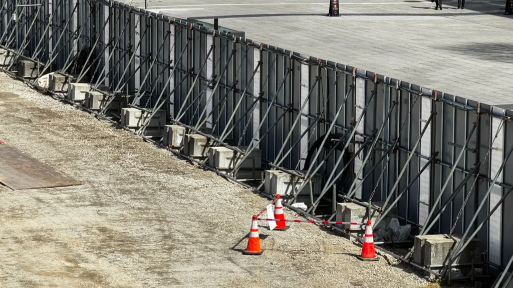
Do not infer bearing capacity, adjustment range or support suitability from quantity drawings alone. These are design and site-condition questions that must be resolved using the applicable engineering information.
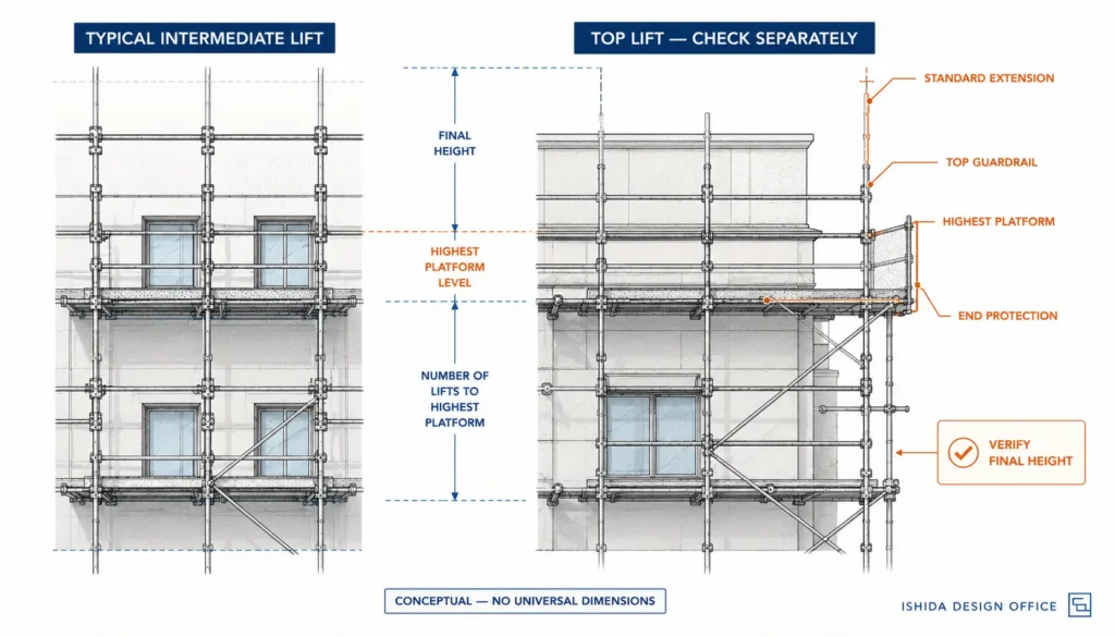
The Top Lift Requires a Separate Check
The top of the scaffold is one of the easiest places to make a quantity error. A typical-lift multiplier may not capture the final standard extension, top guardrails, inner protection, toe boards, end protection or a change in platform level.
Check the dimension to the highest platform and the required protection above it. Then compare that information with standard lengths, joint positions and the detailed top arrangement. Where different elevations finish at different heights, treat each top condition separately.
This is also where drawing inconsistencies become visible. If the written height, number of lifts and top-platform level cannot all be true at the same time, clarify the design before finalizing quantities.
Non-Standard and System-Scaffold Exceptions
System scaffolds are efficient because standard components repeat. Buildings do not always follow that repetition.
Short facade remnants, acute or irregular corners, curved walls, narrow gaps, balconies, canopies, services and access openings may not fit the normal module. These areas must be identified before the main repeated quantity is accepted.
Do not invent a component combination simply to close a geometrical gap in the estimate. Verify that the proposed arrangement is within manufacturer guidance and the approved design. In Great Britain, HSE lists system scaffolds outside manufacturer guidance, along with structures such as cantilevers, complex loading bays, bridges and protection fans, among the scaffold structures that normally require bespoke design. It further states that a scaffold outside recognised standard-configuration criteria or published system-manufacturer guidance requires a specific design produced by a competent person.
For estimating purposes, the safest high-level approach is to isolate the zone, reference the controlling detail and list only resolved components. If the detail is absent, record the zone as pending design clarification rather than burying an assumed quantity in the total.
Theoretical Quantity vs Site Allocation
The exact drawing quantity and the quantity allocated or ordered for site are related but different records.
The drawing quantity is the component count needed for the defined scaffold configuration. A site-allocation quantity may also consider project-approved provisions for handling, replacement, staged work, changes or logistics. The appropriate allowance is not a universal percentage; it varies with the system, supplier, condition of stock, site controls, erection plan and commercial arrangement.
In practice, material shortage can interrupt erection and generate unplanned substitutions. However, hiding a general contingency inside every component count weakens traceability. Preserve the exact takeoff, then show any additional quantity separately with its reason and authorization.
This distinction also improves revision control. When the design changes, the estimator can identify whether the underlying drawing quantity changed or whether only the site-allocation decision changed.
An Illustrative Example
Consider a rectangular renovation scaffold with three visually similar elevations. One elevation includes a recessed entrance, another has a balcony projection, and the third ends below a stepped roof. The gross area calculation suggests that the elevations can be estimated with the same component ratio.
The drawings show otherwise:
- the entrance interrupts a normal bay and affects the platform and bracing arrangement;
- the balcony changes the section and building-side protection;
- the stepped roof changes the number of lifts and the top arrangement;
- tie attachment positions differ because of openings; and
- a return uses a shorter bay size than the main elevation.
For this example, I would count the verified typical zones first, apply the repeated quantities only where the geometry matches, and take off each exception from the relevant plan, elevation, section and detail. This is an illustrative scenario, not a record of a specific project.
Common Material Takeoff Mistakes
1. Using Gross Area as the Final Quantity Basis
Why it matters: Area does not define corners,
access, tie positions, top protection or irregular geometry.
Better approach: Use area for preliminary scale only,
then complete a component takeoff from coordinated drawings.
2. Counting from One View
Why it matters: A plan cannot show every vertical
condition, and an elevation cannot define every width or facade
interface.
Better approach: Reconcile plan, elevation, section,
details and notes.
3. Treating Every Lift as Typical
Why it matters: Platformed lifts, access levels and
the top lift can use different components.
Better approach: Review lift categories and top
conditions separately.
4. Missing Inner Guardrails
Why it matters: The building-side edge may require
protection that is not obvious from the main elevation.
Better approach: Check sections, facade gaps and the
approved protection arrangement by zone and level.
5. Estimating Ties from a Generic Ratio
Why it matters: Real attachment positions, openings
and design conditions can alter the layout.
Better approach: Count the approved tie layout and
distinguish types or duties.
6. Ignoring Short Bays and Returns
Why it matters: Averaging a run can produce the
wrong mix of component sizes.
Better approach: Record every bay-size change and
reconcile shared corner standards.
7. Forgetting Access and Special Structures
Why it matters: Stairs, ladder bays, loading bays,
gates and special support components can form a substantial part of the
list.
Better approach: Maintain separate schedule groups for
access and special zones.
8. Mixing Exact Counts with Allowances
Why it matters: Reviewers cannot see whether a
difference comes from the design or from a logistical decision.
Better approach: Keep exact drawing quantities and
approved additions in separate columns.
9. Using an Obsolete Drawing Revision
Why it matters: Small dimensional or access changes
can affect several component groups.
Better approach: Record the source drawing and revision
for every takeoff zone.
10. Forcing Non-Standard Geometry into a Standard Module
Why it matters: A quantity may be arithmetically
neat but physically or technically unsuitable.
Better approach: Isolate the exception and obtain the
required detail or design confirmation.
Practical Pre-Issue Checklist
Before issuing a scaffold material takeoff, confirm the following.
Document Control
- ☐ Current drawing numbers and revisions are recorded.
- ☐ Scope, phases, inclusions and exclusions are defined.
- ☐ The scaffold system and applicable manufacturer information are identified.
- ☐ Conflicts and missing details are listed for clarification.
Geometry
- ☐ Every scaffold run and return is included.
- ☐ Bay lengths and changes in bay size match the plan.
- ☐ Lift levels and changes in height match the elevations.
- ☐ Scaffold widths and facade interfaces match the sections.
- ☐ The top platform and top protection have been checked separately.
Component Groups
- ☐ Inner and outer standard lines are reconciled.
- ☐ Ledgers and transverse members are separated by size or type.
- ☐ Platformed lifts and deck widths are confirmed.
- ☐ Outer, inner and end guardrails are reviewed separately.
- ☐ Toe boards and other edge-protection components follow exposed edges.
- ☐ Braces match the documented layout.
- ☐ Ties match actual approved positions, types and duties.
- ☐ Stair, ladder, gate and trapdoor components are included.
- ☐ Base and support components reflect actual standard positions and conditions.
Exceptions and Reconciliation
- ☐ Corners, ends, recesses, projections and openings are checked.
- ☐ Entrances, vehicle routes, balconies and roof interfaces are checked.
- ☐ Loading bays, bridges, fans, hoists and cantilevers are scheduled separately.
- ☐ Areas outside a standard system configuration are supported by details or marked pending.
- ☐ Shared components have not been double-counted.
- ☐ Exact drawing quantities are separate from site-allocation additions.
- ☐ The final schedule is cross-checked back to all drawing views.
International and Manufacturer Requirements
Material takeoff is not a substitute for scaffold design or regulatory review. It must reflect the configuration that has been designed and specified for the project.
In Great Britain, HSE guidance says scaffold planning information should include matters such as intended use, height, length, critical dimensions, boarded lifts, working loads, access, sheeting, tie restrictions, ground conditions and relevant building drawings. It also states that system scaffolds should be erected and tied according to manufacturer instructions, and that scaffolds outside recognized standard configurations may require bespoke design.
In the United States, OSHA 29 CFR 1926.451 requires scaffolds to be designed by a qualified person and constructed and loaded in accordance with that design. The same standard contains jurisdiction-specific requirements for platform construction, capacity, and supported-scaffold restraint.
These are separate regulatory contexts. Do not transfer a dimension, tie rule, capacity factor or legal role from one jurisdiction to another. Confirm the applicable law, contract documents, project specification, engineering requirements and manufacturer instructions for the actual work.
A Japanese Practice Perspective
In Japanese scaffold drawing practice, component takeoff often benefits from the same disciplined separation between horizontal geometry, vertical geometry and local interfaces. The plan establishes the bay arrangement around the building; elevations confirm lift-by-lift continuity; and sections reveal the relationship between the working platform, facade and building-side protection.
From my experience preparing scaffold and formwork-support drawings in Japan since 1998, the most important lesson is not that one particular counting formula is superior. It is that the estimate must remain connected to the buildable drawing. Inner and outer guardrails should be checked separately, ties should be counted from their actual layout, and the final height should be reconciled with the top-lift configuration. Standard system repetition should never hide local areas that do not fit the module.
This perspective should not be treated as a universal Japanese specification. Component dimensions, legal requirements and accepted configurations vary by project, manufacturer and jurisdiction. The applicable Japanese regulations, project documents and supplier information must be checked for work in Japan, just as local sources must be checked elsewhere.
FAQ
Can scaffold materials be estimated from square metres alone?
Square metres can support early budgeting or comparison, but they do not define the complete component arrangement. A final takeoff should use coordinated plan, elevation, section and detail information.
Which drawing should I start with?
Start by confirming scope and revisions, then use the plan to divide the scaffold into runs and zones. The working method must still cross-check elevations, sections, details and notes; the plan alone is not enough.
How should scaffold ties be estimated?
Count ties from the approved layout and distinguish relevant types or duties. Check actual attachment locations and drawing coordination rather than applying a universal area ratio.
Should I add extra scaffold materials to the drawing quantity?
Site allocation may include an approved allowance for logistics or operational needs, but there is no universal percentage. Keep any additional quantity separate from the exact drawing takeoff and document the reason.
Why is the top lift easy to underestimate?
The top lift may include standard extensions, guardrails, toe boards, end protection and inner protection that differ from typical intermediate lifts. It may also vary between elevations with different final heights.
What should I do when the system scaffold does not fit an irregular area?
Do not force the standard repetition or invent a component arrangement. Isolate the area, review manufacturer guidance and obtain an approved detail or competent design input where required.
Key Takeaways
- Scaffold area is a preliminary indicator, not a dependable final material list.
- The plan controls horizontal geometry; elevations control vertical repetition; sections and details resolve width and exceptions.
- Typical zones should be counted efficiently, but only after their geometry and component arrangement are verified.
- Inner guardrails, ties and the top lift require separate checks.
- Non-standard system-scaffold areas should be isolated and supported by approved details or design clarification.
- Exact drawing quantities should remain separate from any project-approved site-allocation allowance.
- Every quantity should be traceable to a drawing, zone, revision and component description.
Conclusion
An accurate scaffold material estimate is a controlled translation of drawings into components. The estimator must recognize repetition without overlooking the places where repetition stops.
Begin with coordinated geometry, review each component group, isolate exceptions, and reconcile the final schedule back to the current drawings. That approach produces a takeoff that is easier to explain, revise and use than a quantity derived from scaffold area alone.
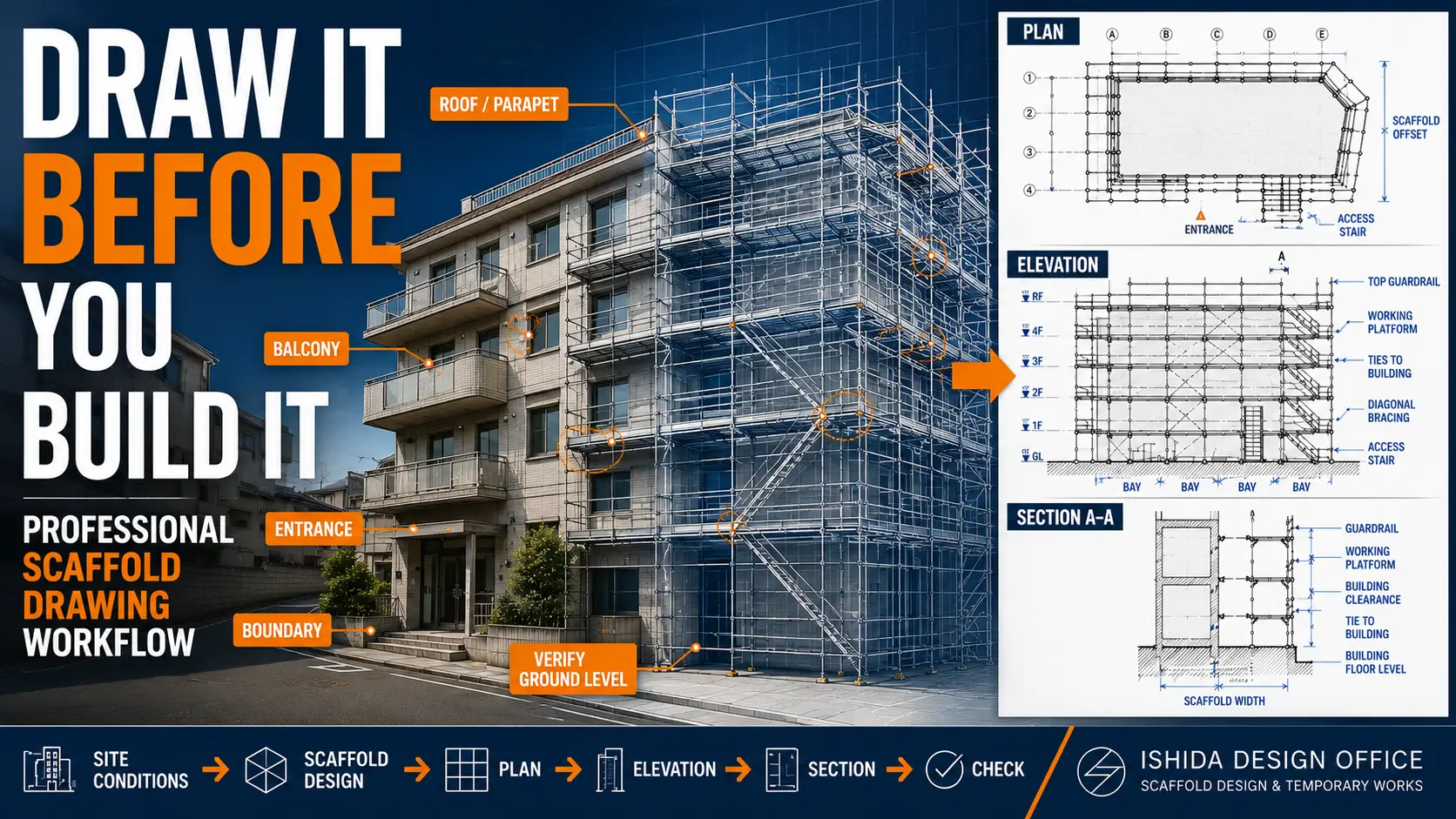
For the broader drawing workflow, continue with How to Create a Scaffold Drawing: Step-by-Step Design Workflow.
Continue the Quantity Estimation Workflow
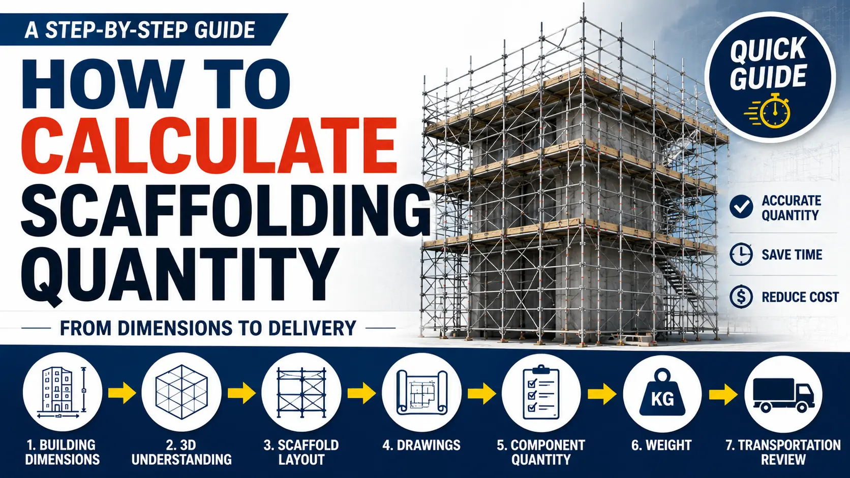
This article focuses on reading scaffold drawings and reconciling the component takeoff. For a broader quantity calculation workflow, including a 3D CAD project example, continue with How to Calculate Scaffolding Quantity: A Step-by-Step Guide.
Once the component quantities have been checked, the next task is to organize them into a bill of materials for review and material planning. See Scaffolding Bill of Materials (BOM): How to Create an Accurate Material List.

Official References
- Health and Safety Executive (HSE): Scaffolds
- Occupational Safety and Health Administration (OSHA): 29 CFR 1926.451 — General Requirements
Article updated: October 28, 2026
Technical references last verified: September 2026
This article is general technical information, not project-specific design, engineering or legal advice. Applicable law, contract documents, project specifications, engineer requirements, manufacturer instructions and site-specific conditions take priority. External guidance may change; verify the current official sources before use.
About the Author
ISHIDA DESIGN OFFICE brings more than 30 years of practical experience in Japan, specializing in scaffolding design, temporary works planning, CAD drafting, quantity estimation, and construction support.
Drawing on experience from residential, commercial, and industrial projects, he shares practical insights that emphasize not only sound engineering design but also buildability, safety, and real-world jobsite application.
At Scaffold Design Hub, he combines practical experience from Japan with official guidance and technical resources from government agencies, manufacturers, and industry organizations around the world to provide reliable, practical information for construction professionals.
To learn more, visit the About page. For questions or project inquiries, please use the Contact page.