
Calculating scaffolding quantity may appear simple at first.
Measure the length of the building, measure the required scaffold height, multiply the two numbers, and you have the scaffold area.
That calculation can be useful.
But it is only the beginning.
A scaffold with an apparent area of 500 m² does not automatically tell you how many standards, ledgers, transoms, decks, braces, ties, base components, guardrails or access components will actually be required.
The final quantity depends on the geometry of the scaffold, the scaffold system, the bay arrangement, lift arrangement, working levels, building shape, access requirements and many other project-specific conditions.
In scaffold design work since 1998, one principle I have found consistently important is that apparently similar buildings can require different scaffold arrangements once their actual geometry and site conditions are examined.
For this reason, scaffold quantity calculation should be treated as a process rather than a single formula.
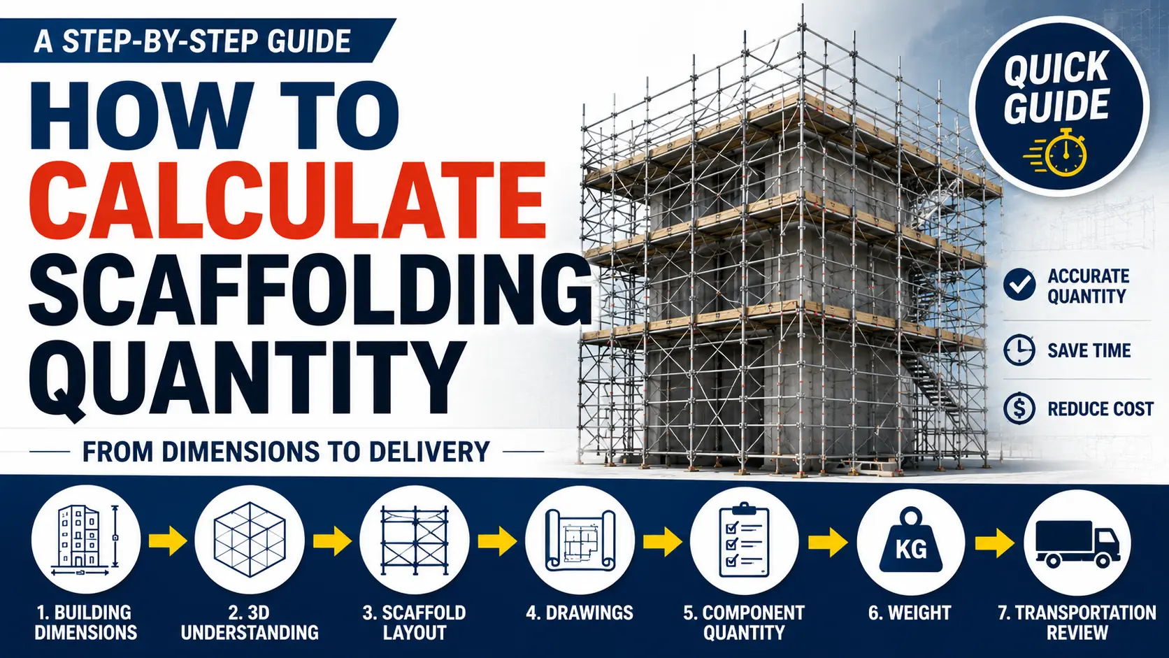
Building Information → Preliminary Estimate → 3D Understanding → Scaffold Layout → Drawing → Component Quantity → Weight → Transportation Review
This article explains each stage without assuming that one calculation method applies to every scaffold system or every country.
IMPORTANT: This guide explains general planning principles. Actual component dimensions, capacities, allowable configurations and engineering requirements depend on the scaffold system, manufacturer documentation, project conditions and applicable regulations.
What Does “Scaffolding Quantity” Actually Mean?
Before performing any calculation, it is important to define what “quantity” means.
Several different quantities may be involved in the same project.
| Quantity | What It Describes | Typical Use |
|---|---|---|
| Scaffold area | Approximate length × height | Early estimating |
| Scaffold volume or spatial extent | Three-dimensional working envelope | Planning |
| Number of bays | Horizontal scaffold arrangement | Layout |
| Number of lifts | Vertical scaffold arrangement | Layout |
| Component quantity | Number of individual scaffold parts | Material takeoff |
| Total material weight | Combined mass of required components | Logistics |
| Transport quantity | Materials organized for delivery | Transportation planning |
These quantities are related, but they are not interchangeable.
A contractor may initially need an approximate scaffold area for budgeting. An estimator may later need actual component quantities. A logistics team may need weights and transport information.
Confusing these stages can create problems.
Why Length × Height Is Only a Starting Point
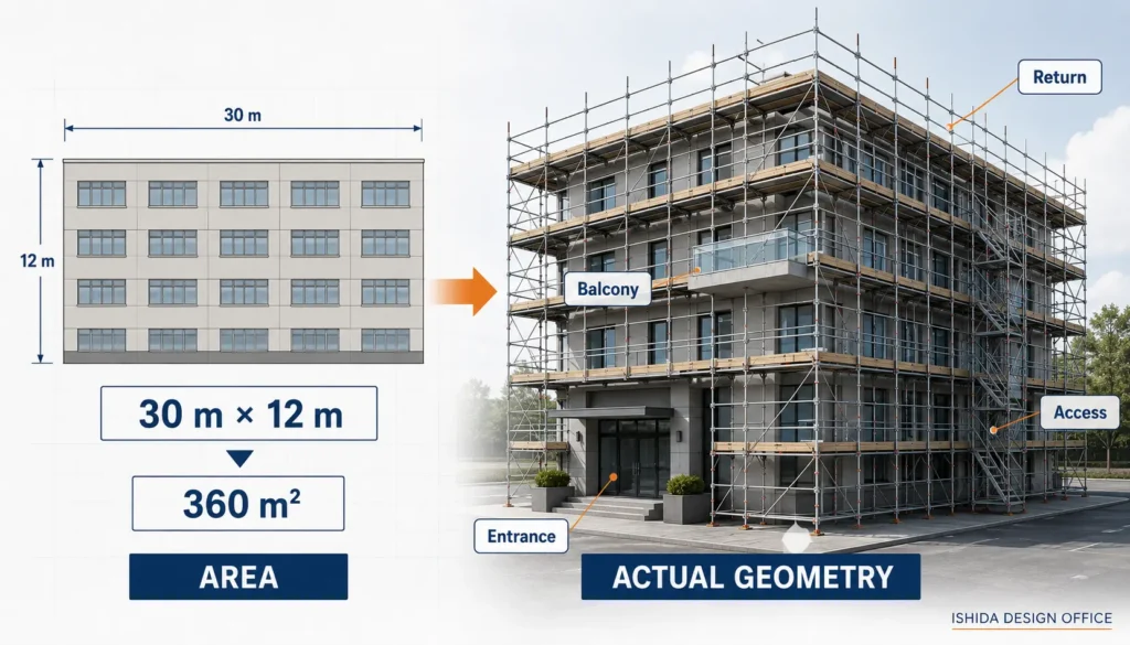
Suppose a façade is:
- 30 m long
- 12 m high
The simple scaffold area is:
30 m × 12 m = 360 m²
That number is useful as an initial reference.
It does not, however, tell us the complete material quantity.
The calculation does not show:
- how the 30 m length will be divided into bays
- whether different bay lengths will be needed
- how many working lifts will be boarded
- whether the scaffold turns around a corner
- whether the building has setbacks
- whether balconies project from the façade
- whether entrances must remain open
- whether a stair tower is required
- where ties can actually be installed
- where bracing can be located
- whether loading bays or other special structures are required
DO NOT ASSUME: Scaffold area is a useful estimating quantity. It is not automatically a final scaffold material quantity.
Information You Need Before Calculating Scaffold Quantity
A reliable calculation begins with reliable information.
Depending on the project, useful input may include:
- building length
- required scaffold height
- building plan
- elevations
- sections
- roof geometry
- balconies and canopies
- façade projections
- entrances
- ground levels
- scaffold width
- intended bay lengths
- intended lift heights
- number of boarded working levels
- access requirements
- loading requirements
- sheeting or netting requirements
- tie restrictions
- ground or support conditions
- delivery and material-handling constraints
Not every project requires exactly the same information.
The important point is to identify missing information before converting an early estimate into a final material order.
HSE guidance in Great Britain similarly identifies information such as scaffold height and length, critical dimensions, boarded lifts, working loads, access arrangements, sheeting or netting, ground conditions, building information and site restrictions as relevant inputs during scaffold planning and design.
Step 1: Calculate the Preliminary Scaffold Area
For a simple façade, the first calculation may be:
Scaffold Area = Scaffold Length × Scaffold Height
For example:
30 m × 12 m = 360 m²
For several elevations, individual areas can be calculated and combined as an initial estimate.
This is useful for:
- early budgeting
- comparing project scale
- preliminary planning
- tender-stage estimation
But it should be labeled correctly.
Use terms such as:
Preliminary Scaffold Area
or
Approximate Scaffold Area
rather than treating it as a confirmed component quantity.
The more irregular the structure becomes, the less information the simple area calculation provides about the actual scaffold configuration.
Step 2: Understand the Scaffold in Three Dimensions
One of the easiest ways to underestimate or misunderstand scaffold quantity is to think only in two dimensions.
A scaffold is a three-dimensional temporary structure.
To understand its quantity properly, consider at least:
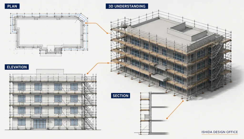
Plan + Elevation + Section
These three views answer different questions.
Plan View
The plan helps define the horizontal arrangement.
It can show:
- building footprint
- scaffold lines
- bay divisions
- corners
- returns
- entrances
- stair towers
- changes in scaffold width
- obstacles
- restricted areas
A straight elevation may appear simple while the plan reveals several returns or changes in direction.
Those changes affect the material quantity.
For a detailed explanation of drawing views, see Scaffold Plan vs Elevation vs Section: What Each Drawing Shows.
Elevation View
The elevation shows the vertical arrangement.
It helps identify:
- total scaffold height
- lift positions
- working platforms
- guardrails
- building levels
- changes in façade height
- roof conditions
- access levels
- potential bracing zones
A building that has one length in plan may have several roof or façade heights.
A single average height can therefore hide important differences.
Section View
The section answers questions that plan and elevation alone may not resolve.
It can show:
- scaffold width
- distance from the façade
- balconies
- canopies
- roof projections
- different working levels
- support conditions
- changes in scaffold geometry
This is why quantity estimation should not be treated only as an area calculation.
Step 3: Establish the Scaffold Layout
Once the overall geometry is understood, the next stage is to determine the scaffold arrangement.
This is where a theoretical building dimension begins to become an actual scaffold.
Bay Arrangement
The total façade length rarely tells you the exact number of bays by itself.
A simple preliminary relationship is:
Approximate Number of Bays = Scaffold Length ÷ Selected Bay Length
If 30 m of scaffold were divided using an illustrative 1.8 m bay:
30 ÷ 1.8 = 16.67
You cannot construct 0.67 of a normal bay.
The layout therefore has to be resolved using components available for the selected scaffold system.
The final arrangement may contain different bay lengths depending on:
- corners
- entrances
- façade projections
- building dimensions
- equipment
- available space
- system limitations
IMPORTANT: The example above is illustrative only and does not recommend 1.8 m as a universal scaffold bay.
For more detail on scaffold geometry, see Scaffold Dimensions Explained: Bay Length, Lift Height, Width & Standards.
Lift Arrangement
The same principle applies vertically.
A preliminary relationship is:
Approximate Number of Lifts = Required Height ÷ Selected Lift Height
But the final vertical arrangement may be affected by:
- building floor levels
- roof lines
- working positions
- access
- platform requirements
- system configuration
Again, a mathematical division is the beginning of the layout, not necessarily the completed layout.
Scaffold Width and Returns
Width also affects material quantity.
A scaffold following a straight wall is different from one that:
- turns around several corners
- surrounds a complete building
- changes width
- crosses projections
- creates returns around balconies or extensions
This is why scaffold quantity is fundamentally a 3D geometry problem as well as an arithmetic problem.
Step 4: Identify the Main Scaffold Components
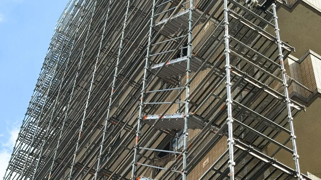
After the scaffold layout has been established, the material structure can be divided into component groups.
Depending on the scaffold system, these may include:
- standards or vertical members
- ledgers or horizontal members
- transoms
- decks or platforms
- base plates
- adjustable bases
- guardrails
- midrails
- toe boards
- braces
- ties
- access components
- stairs or ladder components
The names and exact configurations vary between scaffold systems.
For an overview of scaffold components, see Scaffolding Parts Explained: Names, Sizes and Functions.
The important point is not to jump directly from scaffold area to a component order.
The layout should first show where those components are actually needed.
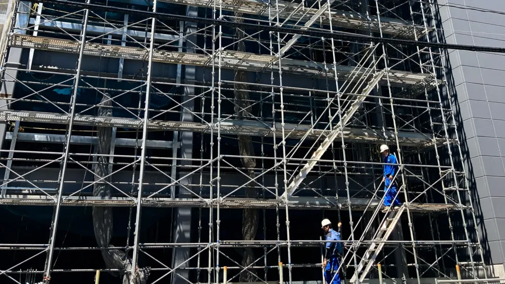
In my scaffold design work, I normally use the quantity calculation function built into the CAD system. I also check the calculated quantities visually against the drawings twice rather than relying on the software output alone. This gives me a separate opportunity to identify differences between the quantities and the scaffold arrangement shown in the drawings.
Step 5: Include Ties, Bracing, Access and Special Components
A quantity estimate based only on the primary scaffold grid will be incomplete.
The scaffold may also require components associated with stability, access and project-specific conditions.
Bracing
Bracing should not simply be added as an arbitrary percentage of the main scaffold quantity.
Its arrangement depends on the scaffold configuration, system requirements, design conditions and applicable guidance.
See Scaffold Bracing Explained: Types, Layout & Design Principles.
Ties
Ties also need separate consideration.
The building must have suitable locations where the specified tie arrangement can actually be achieved.
Openings, balconies, façade geometry and other building features may affect the arrangement.
See Scaffold Ties Explained: Types, Spacing & Layout.
Access
Access components may include:
- ladder bays
- stair towers
- internal ladders
- access gates
- additional guardrails
These can materially affect the total component quantity.
Special Components
Depending on the project, additional items may include:
- loading bays
- bridges
- protection fans
- cantilevered areas
- pedestrian protection
- sheeting or netting components
- additional supports
These should not be hidden inside a generic square-metre calculation.
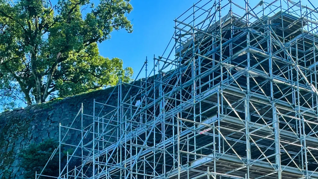
When reviewing scaffold quantities, I pay particular attention to the number of scaffold ties and the arrangement at the top of the scaffold. The component quantities can change depending on how the uppermost section is arranged, so I check these areas against the actual drawing layout rather than treating the initial takeoff as final. Tie quantities and locations must also follow the applicable design and support conditions.
Step 6: Check Areas That Cannot Be Estimated from Area Alone
This step is particularly important.
Consider two buildings with the same total façade area.
Building A
- long straight façade
- uniform height
- few openings
- simple access
Building B
- several corners
- changing roof heights
- balconies
- a canopy
- multiple entrances
- restricted ground space
Both might produce the same nominal scaffold area.
But their actual material quantities can be different.
This is one reason a quantity calculation should be checked against the actual geometry rather than relying exclusively on square metres.
Step 7: Convert Piece Quantities into a Material Schedule
Once the scaffold arrangement is sufficiently defined, component quantities can be organized into a material schedule.
A simplified schedule might look like this:
| Component Group | Size / Type | Quantity | Weight Data | Notes |
|---|---|---|---|---|
| Standards | System-specific | — | — | Verify actual system |
| Ledgers | System-specific | — | — | Separate by length |
| Transoms | System-specific | — | — | Check platform layout |
| Platforms | System-specific | — | — | Check boarded lifts |
| Braces | System-specific | — | — | Based on configuration |
| Ties | System-specific | — | — | Verify attachment conditions |
| Base components | System-specific | — | — | Check support conditions |
| Access components | System-specific | — | — | Stair / ladder arrangement |
Do not combine components of different lengths into one quantity if that information will later be needed for procurement, storage or transportation.
A total of “200 ledgers,” for example, may be less useful than a schedule that separates those ledgers by actual component length.
For a closer look at identifying and checking individual components directly from scaffold drawings, use the material takeoff guide below.

This article: How to develop a realistic scaffold quantity.
Material Takeoff Guide: How to extract and check individual material quantities from drawings.
After calculating and checking the quantities, the next task is to organize the results into a usable bill of materials for ordering and material management.

Step 8: Consider Component Length, Weight and Transportation
A material calculation should not necessarily stop when the number of pieces has been counted.
For logistics planning, the next questions may include:
- What are the component lengths?
- What does each component weigh?
- What is the combined material weight?
- How will different lengths be bundled or handled?
- What are the delivery constraints?
- What vehicle or transport arrangements are appropriate?
- Is there sufficient unloading and storage space?
The exact transport calculation depends on many factors, including local transport regulations, vehicle limits, packaging, loading arrangements and the scaffold system.
For that reason, this article does not provide a universal “pieces per truck” formula.
Material quantity and transportation planning should not be treated as completely separate subjects.
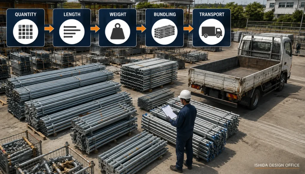
A piece count without component length or mass information may be insufficient for realistic logistics planning.
Step 9: Cross-Check the Quantity Against the Drawings
Before finalizing the material schedule, compare it with the scaffold drawings or detailed layout.
Check the:
- plan
- elevations
- sections
- details
- access arrangement
- ties
- braces
- working platforms
- corners
- returns
- special structures
This is one of the strongest reasons to prepare a proper scaffold drawing for anything beyond the simplest preliminary estimate.
Drawings make the geometry visible.
DRAWING CHECK: Does the material schedule describe the scaffold that is actually shown?
If you need a guide to reading scaffold drawings before performing a material takeoff, see How to Read Scaffold Drawings: Plan, Elevation, Section & Details.
Once the CAD quantity calculation is complete, I cross-check the quantities against the scaffold drawings at least twice. I regard this as a necessary part of preparing the material schedule: the quantities must agree with the scaffold arrangement actually shown on the drawings, even when the takeoff was generated automatically.
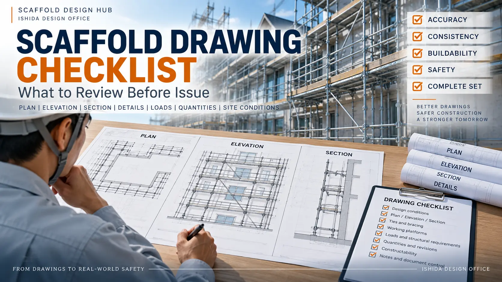
Real Project Case Study: How I Use 3D CAD to Calculate Scaffold Quantities
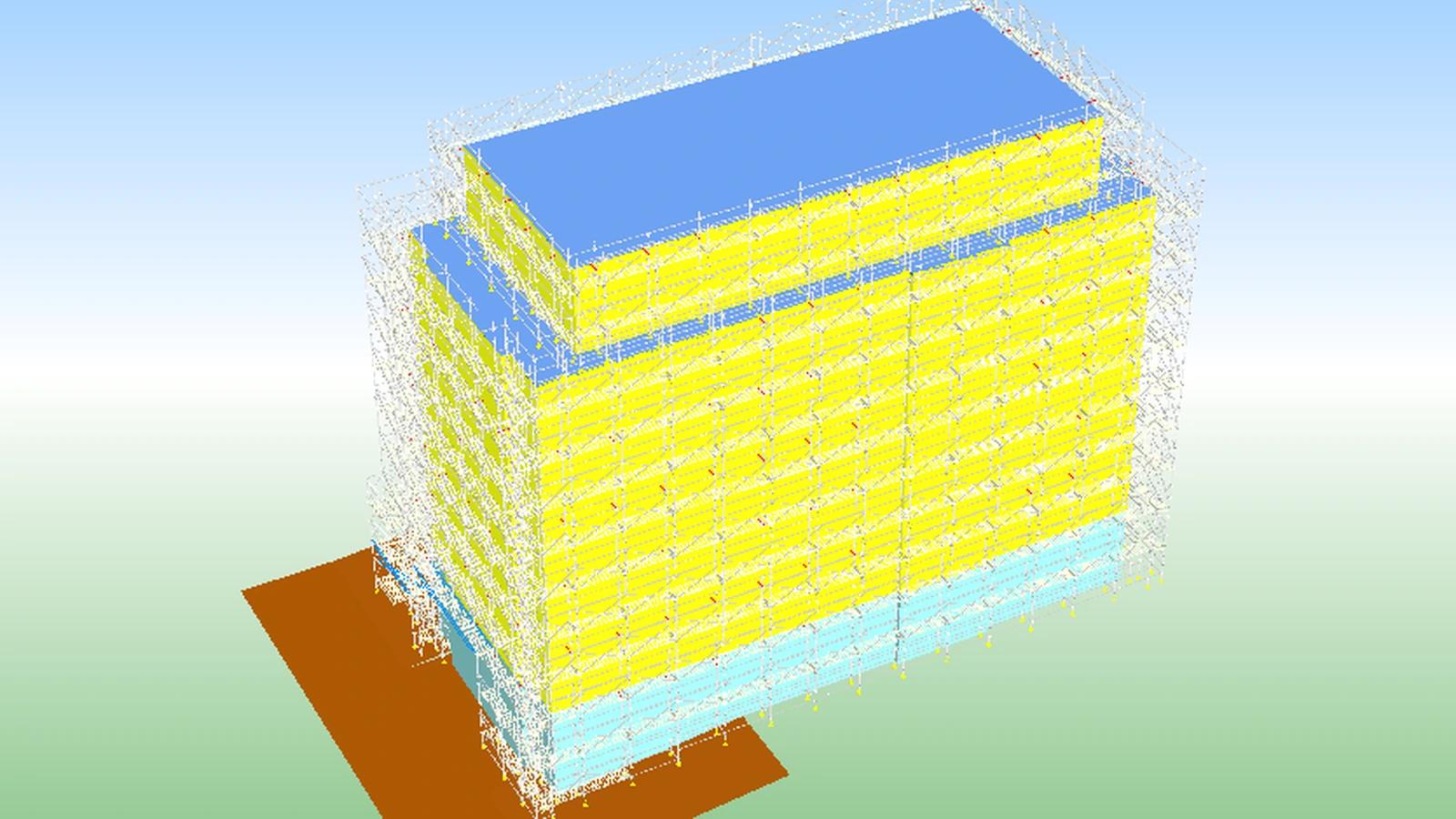
The following example is from a renovation project for which I prepared the scaffold design at ISHIDA DESIGN OFFICE. The project went ahead, and the 3D CAD model and material quantity schedule shown here come from that work. I have removed identifying project information from the schedule.
My quantity calculation starts with the model, not with the material list. If I select the wrong component while building the model, the software may count it perfectly—and still give me the wrong quantity for the scaffold I intended to design.
1. Building the 3D CAD Model with the Correct Components
When I draw a scaffold in 3D CAD, I check the actual members as I place them: standards, horizontal members, working platforms, brackets, guardrails and the other components required by the arrangement. I cannot judge the model by its overall appearance alone. The component type and size matter just as much as the position.
I take particular care at corners, changes in height and places where the available width forces a different layout. Those are the areas where a repeated bay arrangement can stop matching the building.
Once the model is properly developed, I can use its geometry to prepare plan, elevation and section drawings. Working from the same model helps me keep the views consistent, although I still review the resulting drawings.
2. Reviewing the Layout Against the Surrounding Site
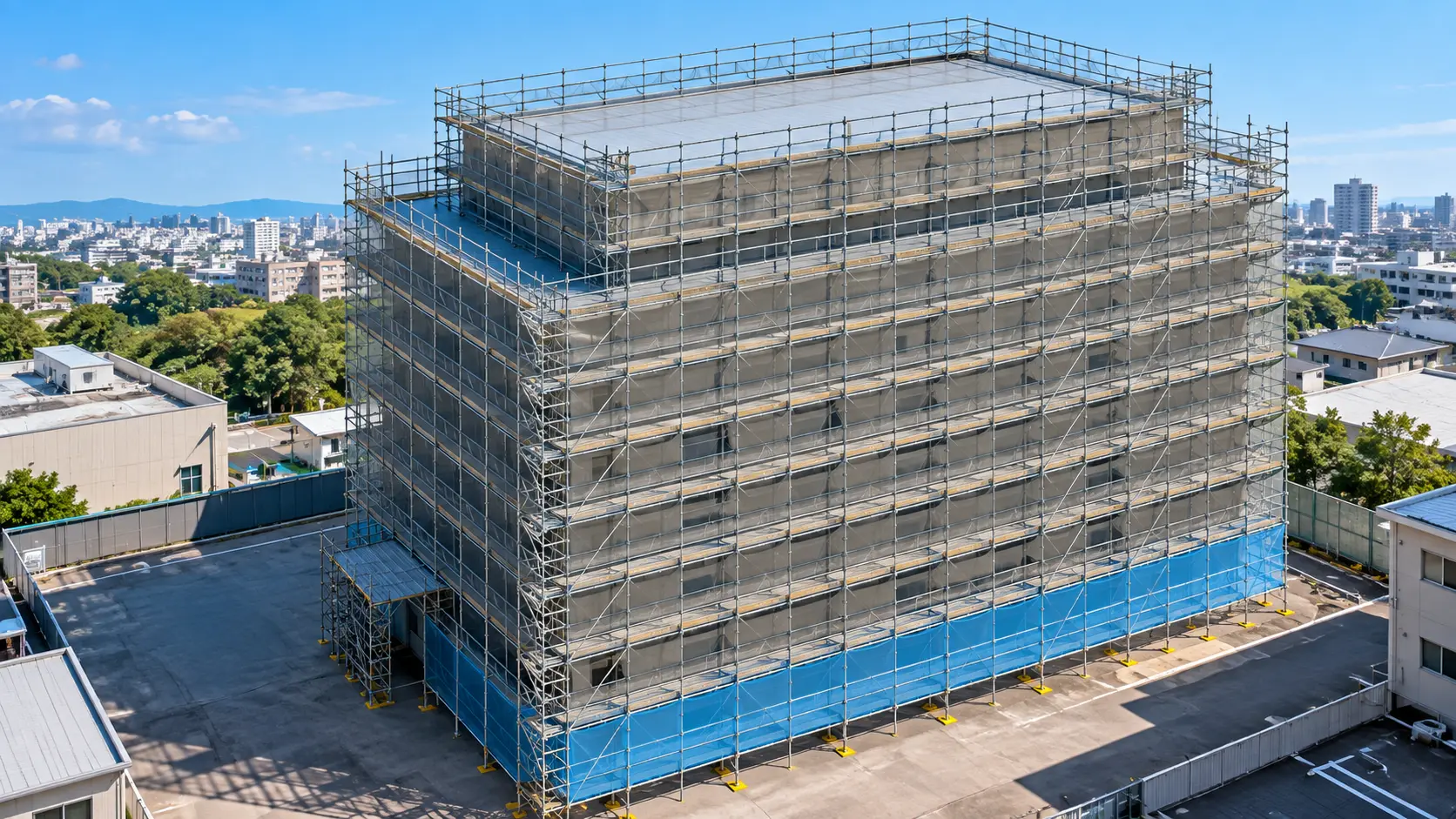
A scaffold can fit the building in a CAD model and still create difficulties on site. I therefore look at the space around the building, including neighboring structures, property boundaries, access routes and the room available for installation.
The visualization below is based on the scaffold design. It makes the overall arrangement easier to picture and can help explain what needs to be checked around the building. It is not a site photograph, however, and it cannot establish the actual location of a boundary or the clearance to a neighboring property. Those dimensions must come from reliable project information and site verification.
3. Generating a Material Schedule from the CAD Data
After developing the model, I use the CAD system’s quantity function to produce a component schedule. It groups the entered parts by their codes and counts them. This is why I spend time checking the model first: a quantity report is only as dependable as the components behind it.
The following anonymized schedule was produced from the same project. Unlike the earlier 30 m × 12 m example in this article, these are actual project figures, not hypothetical quantities.
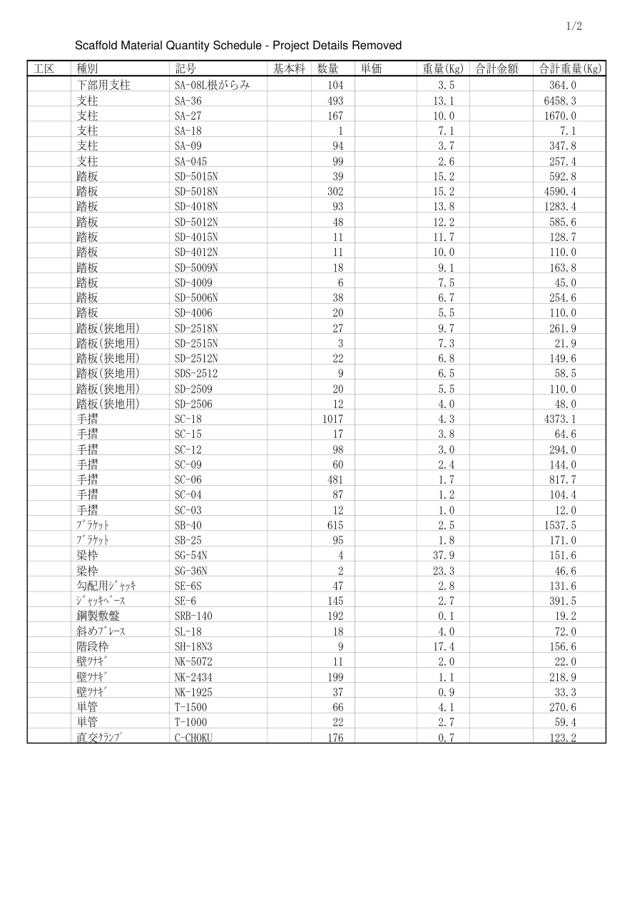
A few entries from the schedule show why a component-by-component calculation is more useful than a single scaffold-area figure:
| Component | Product Code | Calculated Quantity |
|---|---|---|
| Standard | SA-36 | 493 |
| Working platform | SD-5018N | 302 |
| Guardrail | SC-18 | 1,017 |
| Bracket | SB-40 | 615 |
| Adjustable base jack | SE-6 | 145 |
| Wall tie component | NK-2434 | 199 |
For example, the schedule distinguishes a specific standard (SA-36) from other standard lengths, rather than combining every vertical member into one number. That distinction matters when the material list is checked, ordered or prepared for delivery.
4. Checking the Automatic Count Myself
I do not issue a material schedule simply because the CAD system has finished counting. I compare the output with the model and drawings, and I make a second visual check. I pay particular attention to corners, changes in platform length, brackets, wall ties and the uppermost scaffold arrangement.
If a component was entered incorrectly, the software may reproduce that mistake in the schedule. The count may be mathematically consistent with the model while still failing to describe the scaffold required on site.
AI can provide an additional check—for example, by flagging an unusual quantity or a possible arithmetic inconsistency in an exported schedule. I treat those findings as questions to investigate, not as approval of the design. The final decision still requires a comparison with the CAD model, drawings, product information and site conditions.
My practical rule: The more accurately I enter and check the scaffold components in 3D CAD, the easier the quantity calculation becomes. Automation saves time, but it cannot correct a design input that I have not checked.
This case study uses a Japanese wedge-lock scaffold system. Its component codes, dimensions and configurations are specific to that system; they must not be assumed to apply to scaffolds in other countries or to other manufacturers’ products.
Illustrative Example: Why the Same Scaffold Area Can Produce Different Quantities
Consider two hypothetical scaffold projects.
Both have approximately:
- scaffold length: 30 m
- scaffold height: 12 m
- nominal area: 360 m²
Scenario A — Simple Façade
The first façade is:
- straight
- uniform in height
- free from major projections
- accessible from one end
- relatively consistent in bay arrangement
Scenario B — Irregular Façade
The second façade includes:
- two returns
- an entrance that must remain clear
- projecting balconies
- different roof heights
- separate stair access
The nominal area may still be approximately 360 m².
But the component schedule can change because Scenario B requires different geometry.
More corner conditions may affect standards, ledgers and guardrails.
Different heights may affect vertical components.
An entrance may alter the bay arrangement.
Balconies may change scaffold width or require separate consideration.
Access adds another component group.
Equal scaffold area does not necessarily mean equal scaffold material quantity.
This is an illustrative example, not a real project and not a universal calculation rule.
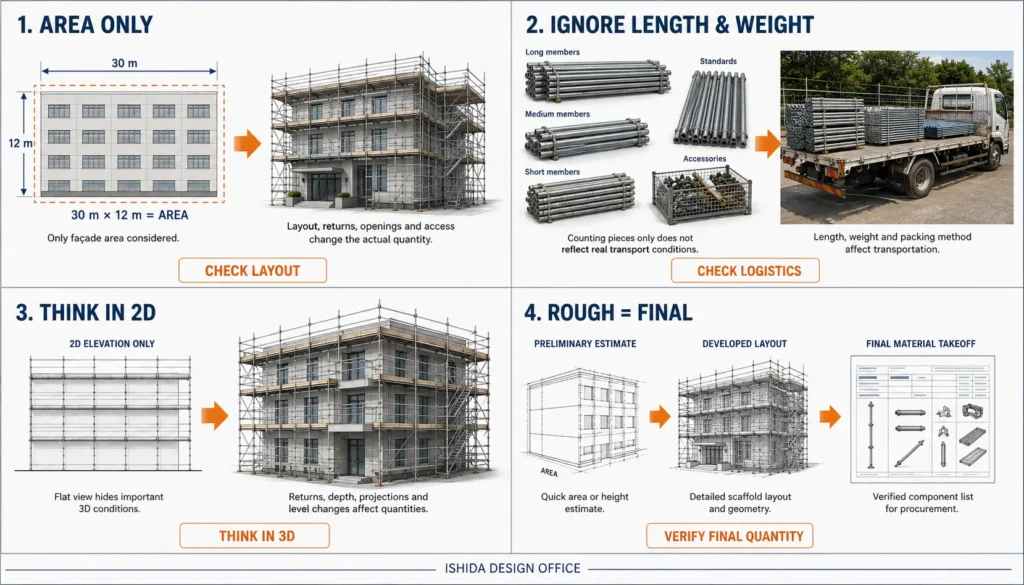
Four Common Scaffold Quantity Calculation Mistakes
Mistake 1 — Calculating from Area and Height Without Creating a Layout
A square-metre estimate can be useful early in a project.
The mistake is treating that figure as if it were already the final scaffold material quantity.
Why it matters:
The calculation does not resolve bays, lifts, corners, access or building interfaces.
Better approach:
Use area for preliminary estimation, then develop the actual scaffold geometry before finalizing component quantities.
Mistake 2 — Ignoring Component Length and Weight When Planning Transportation
A quantity schedule may say that hundreds of scaffold components are required.
That does not automatically tell you how they should be transported.
Why it matters:
Components may have different lengths and weights, and transport conditions vary.
Better approach:
After quantity takeoff, organize components by type and length and use verified manufacturer weight data and applicable transport requirements for logistics planning.
Mistake 3 — Calculating in 2D Without Understanding the Scaffold in 3D
Looking only at building length and height can hide important geometry.
Why it matters:
Returns, width changes, balconies, canopies, roofs, access and level differences exist in three dimensions.
Better approach:
Review plan, elevation and section information together.
Mistake 4 — Treating a Rough Estimate as a Final Material Quantity
Preliminary estimates are useful.
Problems arise when the status of the estimate is forgotten.
Why it matters:
Early estimates often contain assumptions that may change when drawings and site information become available.
Better approach:
Clearly distinguish:
Preliminary Estimate → Developed Quantity → Final Material Takeoff
Practical Scaffold Quantity Calculation Checklist
Before finalizing a scaffold quantity, ask:
Building and Site Information
- ☐ Is the scaffold length confirmed?
- ☐ Is the required height confirmed?
- ☐ Have all elevations been reviewed?
- ☐ Are corners and returns identified?
- ☐ Are balconies, canopies and projections shown?
- ☐ Are entrances and access routes identified?
- ☐ Are ground levels or supporting conditions understood?
Scaffold Geometry
- ☐ Has the bay arrangement been established?
- ☐ Have lift levels been established?
- ☐ Is the scaffold width defined?
- ☐ Have plan, elevation and section been checked together?
- ☐ Have irregular areas been reviewed separately?
Components
- ☐ Are standards accounted for?
- ☐ Are horizontal members separated by size or type?
- ☐ Are working platforms included?
- ☐ Are guardrails and edge-protection components included?
- ☐ Are bases or adjustable components included?
- ☐ Are ties considered?
- ☐ Is bracing considered?
- ☐ Is access included?
- ☐ Are special components identified separately?
Quantity Review
- ☐ Is the scaffold area clearly labeled as preliminary or final?
- ☐ Has the component schedule been checked against the drawings?
- ☐ Are different component lengths separated?
- ☐ Is verified manufacturer weight data available where weight is required?
- ☐ Has transportation been reviewed separately from simple piece count?
- ☐ Have assumptions been documented?
- ☐ Have project-specific requirements been checked?
Japanese Practice Note
In my scaffold and formwork-support design work in Japan since 1998, I have generally found it important not to treat dimensions as isolated numbers.
Building geometry, scaffold width, bay arrangement, lift arrangement, working platforms, ties, bracing, access and surrounding site conditions are interconnected.
A plan may appear straightforward until the elevation reveals different heights. An elevation may appear straightforward until a section reveals a canopy, balcony or restricted clearance. This is one reason I consider plan, elevation and section information together when reviewing scaffold geometry.
The same principle applies to quantity estimation.
A simple area calculation can be useful during preliminary planning, but more detailed material quantities should reflect the scaffold that can actually be arranged for the project.
This is a practical perspective from Japanese design work, not a universal national rule. Scaffold systems, manufacturer requirements, regulations, project specifications and accepted practices differ between countries and projects.
FAQ
Can scaffolding quantity be calculated from square metres alone?
Square metres can provide a useful preliminary estimate, particularly for simple façades.
They do not automatically determine the final number of standards, ledgers, platforms, ties, braces, access components or other scaffold parts.
What is the basic formula for scaffold area?
For a simple façade:
Scaffold Area = Length × Height
For example:
30 m × 12 m = 360 m²
This should normally be regarded as a preliminary area calculation rather than a complete material takeoff.
Do I need a drawing to calculate scaffolding quantity?
Not every early estimate requires a full drawing.
However, as geometry becomes more complex or a reliable component schedule is required, plan, elevation, section or other suitable layout information becomes increasingly important.
In Great Britain, HSE guidance also distinguishes between recognized standard configurations and scaffolds requiring bespoke design and calculation.
Why can two scaffolds with the same area require different quantities?
Because the geometry may be different.
Corners, returns, varying heights, scaffold width, working platforms, entrances, stair towers, ties, bracing and special structures can all change component quantities.
Should scaffold weight be calculated as part of the quantity takeoff?
When weight is relevant to logistics or material planning, component quantities can be combined with verified component weight data.
Support conditions require separate consideration of the actual scaffold configuration, load distribution, working loads, leg loads and support arrangement.
Use manufacturer or supplier information appropriate to the actual scaffold system rather than assumed universal component weights.
How should transportation be calculated?
Transportation should consider more than the total number of pieces.
Component length, weight, bundling, loading method, vehicle capacity, unloading conditions and applicable transport regulations may all be relevant.
There is no universal number of scaffold components that can be assumed to fit on one vehicle.
Key Takeaways
- Length × height calculates preliminary scaffold area, not the complete material quantity.
- Scaffold quantity should be understood in three dimensions using plan, elevation and section information where appropriate.
- Bay arrangement, lift arrangement, width, returns, access, ties, bracing and special conditions can materially change the quantity.
- A reliable component schedule should describe the scaffold actually shown in the layout or drawings.
- Piece quantity alone may not be sufficient for logistics; component lengths and verified weights may also be needed.
- Preliminary estimates and final material takeoffs should be clearly distinguished.
- Actual requirements depend on the scaffold system, manufacturer instructions, project conditions and applicable regulations.
Final Thoughts
Scaffolding quantity calculation is often presented as a simple mathematical exercise.
For an early estimate, it sometimes can be.
For a reliable material quantity, however, the more important question is not simply:
“What is the scaffold area?”
It is:
“What scaffold arrangement is actually required for this building and these site conditions?”
Once the scaffold has been understood in three dimensions and translated into a workable layout, the material quantity becomes much more meaningful.
From there, the next step is to extract and verify the individual components.
Continue with How to Estimate Scaffold Materials from Drawings.
Official References
OSHA — 29 CFR 1926.451, General Requirements for Scaffolds
OSHA requires scaffolds and scaffold components to meet specified capacity requirements and requires scaffolds to be designed by a qualified person and loaded in accordance with that design.
Jurisdiction: United States.
Official source: OSHA — 29 CFR 1926.451
OSHA — Appendix A to Subpart L, Scaffold Specifications
Provides non-mandatory scaffold specifications and guidance supporting compliance with Subpart L. OSHA specifically notes that the appendix does not contain all information necessary to design every complete scaffold system.
Jurisdiction: United States.
Official source: OSHA — Appendix A to Subpart L
Health and Safety Executive — Scaffolds
HSE guidance explains scaffold planning and design considerations in Great Britain, including dimensions, working loads, boarded lifts, access, building information, ground conditions and site restrictions. It also distinguishes recognized standard configurations from scaffolds requiring bespoke design and calculation.
Jurisdiction: Great Britain.
Official source: Health and Safety Executive — Scaffolds
Last Verified: September 2026
Regulations, official guidance and manufacturer documentation may change. Always confirm the current requirements applicable to the project location, scaffold system and intended use.
This article is general technical information and is not a substitute for project-specific engineering, applicable law, contract documents, project specifications, manufacturer instructions or competent professional review.
About the Author
ISHIDA DESIGN OFFICE brings practical experience in Japan since 1998, specializing in scaffolding design, temporary works planning, CAD drafting, quantity estimation, and construction support.
Drawing on experience from residential, commercial, and industrial projects, he shares practical insights that emphasize not only sound engineering design but also buildability, safety, and real-world jobsite application.
At Scaffold Design Hub, he combines practical experience from Japan with official guidance and technical resources from government agencies, manufacturers, and industry organizations around the world to provide reliable, practical information for construction professionals.
To learn more, visit the About page. For questions or project inquiries, please use the Contact page.