A scaffold drawing should not be issued simply because the plan, elevation and dimensions look complete.
Before release, the drawing set should be reviewed as a coordinated technical document. The scaffold geometry, building conditions, working platforms, ties, bracing, access, loads, bases, quantities, notes and revisions should agree with one another and with the design conditions used to produce the drawing.
This is especially important after changes. A correction made on the plan may also affect an elevation, section, detail, material quantity or structural requirement. If those related items are not updated together, each drawing may appear reasonable when viewed separately while the complete drawing set contains contradictions.
ISHIDA DESIGN OFFICE has been involved in scaffold and formwork-support design work in Japan since 1998. One practical lesson from long-term drawing work is that a scaffold drawing should not be reviewed one sheet or one view at a time. The relationship between the drawings is just as important as the information shown on each individual view.
This guide provides a practical pre-issue scaffold drawing checklist for designers and other construction professionals reviewing scaffold drawings before they are released.
IMPORTANT: This is a general drawing-review framework, not a universal design standard. Applicable regulations, project specifications, manufacturer documentation, engineering requirements and site-specific conditions always take priority.
Why a Pre-Issue Scaffold Drawing Review Matters
A scaffold drawing communicates much more than where scaffold components are positioned.
Depending on the project and scaffold system, it may communicate:
- scaffold geometry;
- bay arrangement;
- lift levels;
- working platform locations;
- access;
- ties;
- bracing;
- bases and support conditions;
- special configurations;
- design loads;
- restrictions or notes;
- and relationships with the building and surrounding site.
Official guidance also demonstrates why these conditions matter.
For example, the UK Health and Safety Executive identifies scaffold type, bay lengths, lift heights, platform arrangements, load class, leg loads, tie requirements and additional elements such as loading bays or bridges among the information that may need to be established by scaffold design or a recognised configuration.
In the United States, OSHA requires scaffolds to be designed by a qualified person and constructed and loaded in accordance with that design. OSHA’s scaffold requirements also address matters such as capacity, platforms, foundations, access, ties or bracing, fall protection and falling-object protection. These are US requirements and should not be treated as universal rules for other jurisdictions.
The practical purpose of a pre-issue review is therefore not merely to find drafting errors.
It is to ask: Does the complete drawing set accurately communicate the scaffold that has actually been planned?
1. Confirm the Basic Design Conditions
Start by confirming that the basic conditions shown on the drawings still correspond with the current project information.
Typical items include:
- building geometry;
- site boundaries;
- scaffold type or system;
- bay lengths;
- lift heights;
- scaffold width;
- working levels;
- reference elevations;
- base levels;
- and important site restrictions.
A drawing can be internally neat but still be wrong if it was developed from outdated architectural information or an earlier site condition.
Check building geometry
Compare the scaffold arrangement with the information used to define the building.
Look for:
- façade offsets;
- recesses;
- projections;
- balconies;
- roofs;
- entrances;
- corners;
- level changes;
- and other geometry that affects the scaffold.
Do not assume that a repetitive building elevation means the scaffold can also remain repetitive.
Check the principal scaffold dimensions
Bay length, lift height and scaffold width are interrelated with building geometry, work requirements and system limitations.
If you need a detailed explanation of these dimensional relationships, see Scaffold Dimensions Explained: Bay Length, Lift Height, Width & Standards.
Check reference levels
A missing or inconsistent level can create problems that are difficult to see on a plan.
Confirm where necessary:
- ground level;
- working platform elevations;
- roof levels;
- entrance levels;
- changes in ground elevation;
- and the reference datum used across the drawing set.
2. Review the Scaffold Plan
The plan is usually the best place to understand the horizontal relationship between the scaffold and the building.
However, it should not be reviewed in isolation.
Building-to-scaffold clearance
Confirm that the scaffold follows the actual building geometry and that the intended relationship with the façade is clear.
Pay particular attention where the building geometry changes.
Corners
Corners can create geometry that does not fit a simple repeating bay arrangement.
Check that:
- the scaffold returns correctly;
- working platforms remain coordinated;
- the inside and outside standards make sense;
- and the corner arrangement corresponds with the elevations and sections.
Entrances and openings
Entrances, garage doors, large windows and other openings may affect:
- standards;
- working platforms;
- braces;
- ties;
- access;
- and local structural requirements.
An opening shown clearly on the architectural information should not disappear from the scaffold planning process.
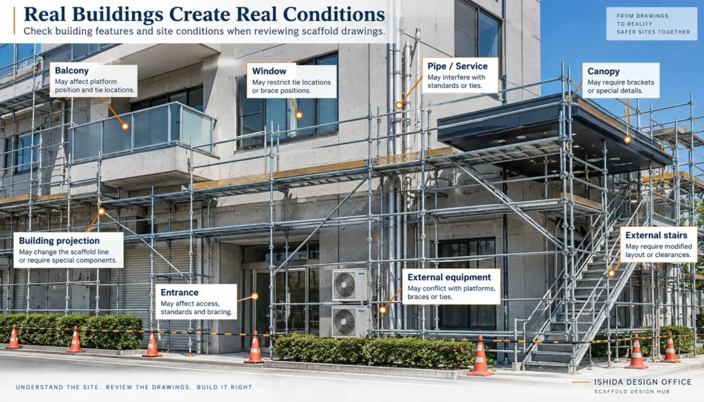
Obstacles and services
Check known:
- pipes;
- signs;
- equipment;
- roof projections;
- canopies;
- external stairs;
- mechanical services;
- and other fixed obstacles.
A scaffold can fit geometrically around a building while still being impractical because a critical component conflicts with an existing object.
Site boundaries
Check the relationship between the scaffold and:
- property boundaries;
- neighbouring structures;
- roads;
- pedestrian routes;
- access routes;
- and available erection space.
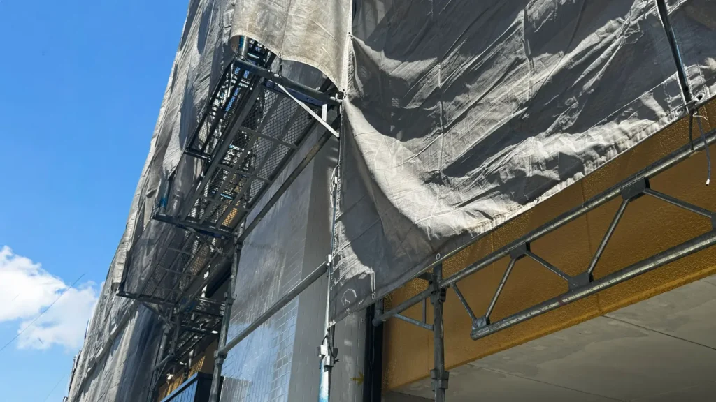
Brackets and projections
Where brackets, extended platforms or other projections are used, make sure they are shown consistently wherever they affect the geometry.
3. Review the Elevations
The elevation reveals issues that may not be visible on plan.
Review each relevant elevation rather than assuming that one façade represents the others.
Overall scaffold height
Check:
- start level;
- top level;
- number of lifts;
- working levels;
- and changes in height along the building.
Top lift
The uppermost part of the scaffold often deserves separate attention.
Confirm that the top condition shown in the elevation corresponds with the building height, roof condition, work area and edge-protection arrangement intended for the project.
Guardrails and edge protection
Where these elements need to be communicated on the drawing, check that they appear on the relevant working levels and exposed edges.
The exact regulatory requirements vary by jurisdiction. For example, OSHA specifies fall-protection and guardrail requirements for scaffolds used in the United States.
Bracing
Check whether the bracing shown in elevation is compatible with:
- openings;
- access;
- platform locations;
- building projections;
- and other scaffold components.
For more detail, see Scaffold Bracing Explained: Types, Layout & Design Principles.
Ties
Do not check ties only as a repeating symbol pattern.
Ask whether the indicated locations correspond with the building geometry and with locations where attachment may actually be possible.
For a detailed introduction to ties, see Scaffold Ties Explained: Types, Spacing & Layout.
4. Check Sections and Details
Sections are essential where the relationship between the scaffold and the building cannot be understood clearly from the plan and elevation alone.
A section may reveal a problem that is almost invisible in the other views.
Building-to-platform relationship
Check the distance and vertical relationship between the working platform and the work face.
Review changes caused by:
- balconies;
- setbacks;
- roofs;
- ledges;
- structural projections;
- and level differences.
Working platforms
Check that the platform arrangement shown in section corresponds with the plan and elevation.
Do not allow a platform to appear in one view but disappear or change position in another.
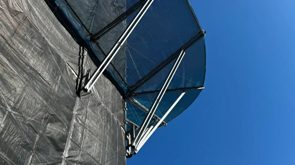
Brackets
Where brackets are used to modify the working width or platform position, the section is often one of the most important views for communicating the arrangement.
Ties
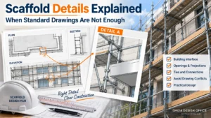
Where the tie connection depends on building geometry, a detail or section may be required to explain what a plan or elevation symbol cannot communicate adequately.
Bases and supporting conditions
Check whether unusual ground, slab, roof or support conditions require additional information.
For background on base plates, sole boards and supporting conditions, see Scaffold Base Design: Base Plates, Sole Boards and Ground Conditions.
Special areas
Do not force an unusual condition into a standard detail if the standard detail no longer explains the actual arrangement.
A project-specific detail may be necessary where there are unusual:
- openings;
- projections;
- transitions;
- support arrangements;
- access interfaces;
- or structural conditions.
5. Review Safety-Related Drawing Information
A pre-issue drawing review should also check whether safety-related features that form part of the planned scaffold have been communicated consistently.
Depending on the project and jurisdiction, these may include:
- guardrails;
- intermediate rails or equivalent protection;
- toe boards;
- working platforms;
- access arrangements;
- open edges;
- openings;
- falling-object protection;
- and required local reinforcement.
This does not mean the drawing reviewer should invent requirements that are not part of the applicable design or regulation.
Instead, the question is:
DRAWING CHECK: Have the relevant safety provisions established for this scaffold been communicated correctly on the drawing?
OSHA, for example, contains specific US requirements for scaffold access, fall protection, guardrails and falling-object protection.
A project elsewhere may be governed by entirely different statutory requirements.
6. Check Loads and Structural Requirements
One of the most important pre-issue checks is the relationship between structural requirements and the drawing.
A calculation and a drawing are not separate worlds.
If a structural review requires a change to the scaffold configuration, the issued drawing should communicate that change wherever necessary.
Confirm the intended use
Check whether the drawing and design information reflect the intended use of the scaffold.
Consider whether the scaffold is intended for:
- personnel access;
- normal working operations;
- material storage;
- material handling;
- loading areas;
- equipment;
- or other project-specific uses.
The load condition should not be guessed when the intended use is unclear.
For a broader explanation, see Scaffold Load Capacity Explained: Dead, Live and Environmental Loads.
Check concentrated or unusual loads
A locally concentrated load can require different consideration from a generally distributed working load.
Areas involving equipment, material concentrations or special loading conditions should therefore be identified and reviewed as individual design conditions where necessary.
Check ties and bracing
Where stability requirements depend on ties, bracing or other stabilising elements, make sure the drawing contains the arrangement that corresponds with the design.
The HSE notes that scaffold design information may include tie spacing, tie duty, maximum leg loads and details of additional elements where relevant.
Check bases and supports
Structural requirements do not end at the lowest standard.
If the scaffold relies on a particular base or support condition, confirm that the drawing communicates the relevant condition rather than assuming that the site team will infer it.
Confirm that calculated reinforcement reached the drawing
This is a particularly important practical check.
A calculation may correctly identify that reinforcement or a configuration change is required, but that does not help the construction team if the final drawing still shows the previous arrangement.
The reviewer should therefore ask:
DRAWING CHECK: Has every relevant structural requirement been transferred into the drawing set?
7. Cross-Check the Drawing Against Material Quantities
Where the drawing is also being used as the basis for estimating or preparing a bill of materials, drawing revisions can affect quantities.
Typical items include:
- standards or uprights;
- ledgers and transoms;
- platforms;
- guardrails;
- braces;
- ties;
- brackets;
- access components;
- and special components.
A change that looks minor graphically can alter several material quantities.
For example, changing:
- the number of bays;
- scaffold height;
- platform arrangement;
- tie arrangement;
- or a special projection
may affect multiple component groups.
This does not mean every drawing issue requires a complete estimating exercise. It means that where material quantities are linked to the drawing, significant design revisions should not be allowed to leave the quantity information behind.
Useful related guides include:
- How to Estimate Scaffold Materials from Drawings
- How to Calculate Scaffolding Quantity: A Step-by-Step Guide
- Scaffolding Bill of Materials (BOM): How to Create an Accurate Material List
Field Experience: Estimates and Drawing Quantities
In my scaffolding drawing work in Japan, I encountered a substantial difference between a broad area-based estimate prepared on site and the quantities required by the actual scaffold arrangement. I also experienced drawing revisions that changed the material quantities. These are two reasons I treat a square-metre estimate as a preliminary approximation, not as confirmation of the components shown on a drawing.
The pre-issue check is not only whether a quantity list exists. It is whether that list reflects the current drawing revision and the components actually specified. The method and level of detail must suit the project.
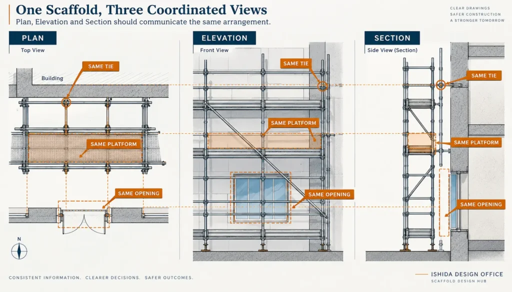
8. Check Consistency Between Plan, Elevation and Section
This is one of the most important parts of a scaffold drawing review.
A plan, elevation and section can each look correct individually while contradicting one another.
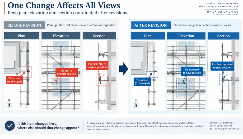
Tie-location mismatch
A tie may appear in a reasonable position on the plan but at a different location on the elevation.
If both drawings are issued, which one should the site follow?
The problem is not necessarily the tie itself. The problem is that the drawing set no longer communicates one coordinated design.
Platform mismatch
A working platform may be shown on the elevation but omitted from the relevant section.
Or a bracket may be added in plan without the resulting platform position being updated in section.
Height mismatch
The number of lifts shown on one elevation may not correspond with the level information shown elsewhere.
Opening mismatch
A building opening may be accommodated on the plan but ignored on the elevation, allowing a brace, tie or other component to pass through the opening graphically.
Revision propagation
A particularly common risk occurs after drawing corrections.
Suppose a project change requires a scaffold bay, tie, platform or other element to move.
The designer updates the plan.
But the same element still appears in its previous position on:
- the elevation;
- the section;
- the detail;
- or another related drawing.
The original correction may have been correct, yet the issued drawing set is now inconsistent because the change was not propagated across every affected view.
A useful review question is therefore:
REVISION CHECK: If this item changed here, where else should that change appear?
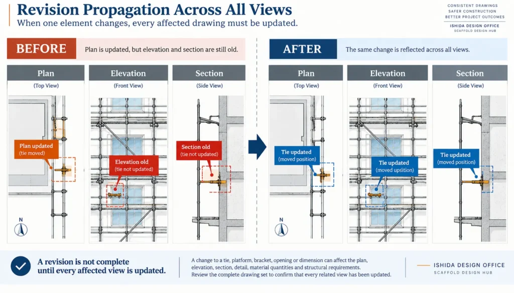
This question is simple, but it catches a different class of error from ordinary drafting checks.
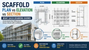
For more background on the role of each drawing view, see Scaffold Plan vs Elevation vs Section: What Each Drawing Shows.
Field Experience: A Change Was Not Carried Across Every View
I have experienced a plan drawing being corrected while the corresponding elevation or section was not updated. I have also found dimensional and component-label errors that required correction. These are not merely drafting issues: conflicting views or labels can leave the recipient unsure which arrangement or component is intended.
For that reason, the question I want a pre-issue review to answer is whether the drawing set communicates one consistent arrangement—not simply whether each sheet looks complete in isolation.
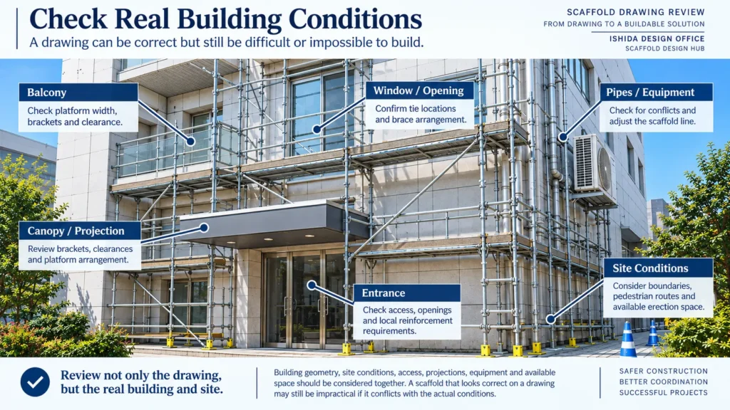
9. Check Whether the Proposed Scaffold Can Actually Be Built
A drawing can be geometrically consistent and still contain an impractical arrangement.
This is why drawing review should include a basic check against known building and site conditions.
Tie locations are a good example
A regular tie pattern may look logical on an elevation.
But the selected locations may coincide with:
- windows;
- openings;
- balconies;
- canopies;
- façade recesses;
- equipment;
- or other areas where the intended connection cannot actually be made.
The drawing should therefore not be reviewed only for graphical regularity.
The reviewer should also consider whether the building offers a realistic interface at the proposed location.
Building geometry, site conditions, access, projections, equipment and available space should be considered together rather than independently.
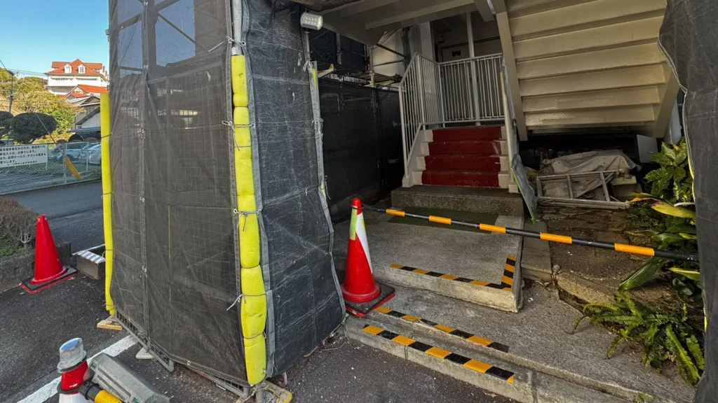
Check access routes
Ask whether ladders, stairs or other intended access arrangements conflict with:
- braces;
- platforms;
- building entrances;
- site traffic;
- or restricted areas.
Check construction space
A completed scaffold may fit within the available footprint but still leave insufficient space for erection, access or a necessary site operation.
That issue belongs mainly to constructability review rather than drawing QA, but obvious conflicts should be identified before issue.
For a more detailed review of this subject, see How to Review Scaffold Drawings for Site Constructability.
10. Check Revisions, Notes and Drawing Information
The technical arrangement may be correct while the document control information is not.
Before issue, check the drawing itself as a controlled document.
Dimensions
Look for:
- missing dimensions;
- duplicated dimensions;
- conflicting dimensions;
- dimensions that no longer match revised geometry;
- and dimensions referring to deleted elements.
Notes
Check whether:
- necessary notes are present;
- obsolete notes remain;
- notes contradict the drawing;
- and revised conditions require revised wording.
Drawing number
Confirm that the intended drawing number is shown and that related sheets are identified correctly.
Revision
Confirm that:
- the current revision is shown;
- revised areas have been updated as required by the project’s document-control procedure;
- obsolete revision information has not accidentally remained;
- and the issued drawing corresponds with the current design information.
Date
Check the issue or revision date in accordance with the project’s documentation system.
Drawing symbols and abbreviations
Symbols should remain consistent and understandable throughout the set.
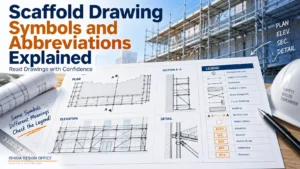
For guidance on common drawing notation, see Scaffold Drawing Symbols and Abbreviations Explained.
Field Experience: Repeated Revisions and Component Differences
On a large construction project in Japan, I had to revise scaffold drawings repeatedly in response to comments from the main contractor and site personnel. Some of the site requirements had not been brought together clearly before the drawing work proceeded. The experience taught me that revision control cannot compensate for unclear instructions: the design conditions and requested changes also need to be confirmed.
I have also made and corrected mistakes involving scaffold components from different manufacturers. In Japan, platform units described by nominal widths such as W500 and W400 are a practical example of why familiar-looking component names should not replace a check of the actual system and dimensions. A width or component-label error can affect both the drawing and the material take-off.
The checklist below is a review aid, not a substitute for project-specific engineering, manufacturer documentation or the applicable requirements.
Final Scaffold Drawing Pre-Issue Checklist
The following checklist can be used as a high-level review sheet before a scaffold drawing is issued.
It should be adapted to the applicable scaffold system, project, jurisdiction, design responsibility and company procedures.
A. Basic information
- ☐ Current building information has been used
- ☐ Scaffold type or system is correctly identified where required
- ☐ Bay arrangement has been reviewed
- ☐ Lift levels have been reviewed
- ☐ Scaffold width has been reviewed
- ☐ Reference levels and elevations are consistent
- ☐ Site boundaries and major constraints have been considered
B. Plan
- ☐ Scaffold follows the intended building geometry
- ☐ Building-to-scaffold relationship is clear
- ☐ Corners have been reviewed
- ☐ Entrances and openings have been considered
- ☐ Known obstacles and equipment have been considered
- ☐ Boundaries and access routes have been considered
- ☐ Brackets or projections are shown consistently
C. Elevations
- ☐ Overall scaffold height is correct
- ☐ Number and position of lifts are consistent
- ☐ Top-lift arrangement has been checked
- ☐ Working platforms are correctly shown
- ☐ Bracing is shown where required by the design
- ☐ Ties are shown where required by the design
- ☐ Openings and façade features correspond with the building information
D. Sections and details
- ☐ Building-to-platform relationship is clear
- ☐ Working-platform positions match other views
- ☐ Brackets are correctly represented
- ☐ Relevant tie interfaces are clear
- ☐ Base/support conditions are shown where necessary
- ☐ Non-standard areas have sufficient detail
E. Safety-related information
- ☐ Relevant edge protection is shown
- ☐ Access arrangements are identified where required
- ☐ Open edges and openings have been considered
- ☐ Applicable project-specific protective measures are reflected
- ☐ Safety-related notes agree with the current drawing configuration
F. Loads and structural requirements
- ☐ Intended scaffold use is understood
- ☐ Relevant load conditions correspond with the design basis
- ☐ Special or concentrated loading areas have been identified where applicable
- ☐ Tie requirements are reflected in the drawing
- ☐ Bracing requirements are reflected in the drawing
- ☐ Base/support requirements are reflected in the drawing
- ☐ Required reinforcement or structural changes from calculations are shown
- ☐ Drawing configuration agrees with the current structural design information
G. Quantities
- ☐ Significant geometry changes have been considered in material quantities
- ☐ Platform quantities correspond with the current drawing
- ☐ Tie and brace quantities correspond with the current arrangement where applicable
- ☐ Special components added or removed by revisions have been considered
- ☐ BOM or material takeoff has been updated where required
H. Drawing coordination
- ☐ Plan and elevations agree
- ☐ Plan and sections agree
- ☐ Elevations and sections agree
- ☐ Details agree with the general arrangement
- ☐ Tie positions are consistent across relevant views
- ☐ Platform positions are consistent across relevant views
- ☐ Bracing positions are consistent across relevant views
- ☐ All affected drawings reflect the latest design changes
I. Constructability
- ☐ Proposed tie locations correspond with realistic building interfaces
- ☐ Bracing does not obviously conflict with access or openings
- ☐ Platforms do not obviously conflict with building projections
- ☐ Access arrangements are compatible with the scaffold configuration
- ☐ Known site constraints have been considered
J. Document control
- ☐ No important dimensions are missing
- ☐ No contradictory dimensions remain
- ☐ Notes are current
- ☐ Obsolete information has been removed
- ☐ Drawing number is correct
- ☐ Revision is correct
- ☐ Date is correct
- ☐ Symbols and abbreviations are consistent
- ☐ The complete drawing set represents one coordinated design
What a Pre-Issue Drawing Review Does Not Replace
A checklist improves consistency, but it does not replace engineering judgment.
It also does not replace:
- required structural calculations;
- manufacturer instructions;
- project specifications;
- applicable regulations;
- competent or qualified design input where legally required;
- site-specific engineering assessment;
- erection procedures;
- or inspection of the erected scaffold.
For example, HSE states that temporary structures must be designed, installed and maintained to withstand foreseeable loads and used for their intended purpose.
Similarly, OSHA requires scaffolds within its jurisdiction to be designed by a qualified person and constructed and loaded in accordance with that design.
A drawing checklist is therefore a communication and coordination control, not a substitute for the underlying design process.
FAQ
What should be checked before a scaffold drawing is issued?
At minimum, review the basic design conditions, scaffold geometry, plan, elevations, sections, platforms, ties, bracing, bases, access, relevant safety information, load-related requirements, revisions and consistency between all affected drawings.
The exact scope depends on the scaffold, jurisdiction, project specifications and design responsibility.
Why should plan, elevation and section be checked together?
Because a revision may affect more than one view.
A tie, platform, bracket, opening or scaffold dimension can be corrected on one drawing while remaining unchanged elsewhere. Reviewing the views together helps identify these coordination errors.
Should the scaffold drawing be checked against the structural calculation?
Where a structural calculation forms part of the design, the final drawing should reflect relevant calculated design requirements.
A calculation that requires a configuration change or reinforcement is not fully communicated if the issued drawing still shows the previous arrangement.
Can a scaffold drawing be correct but still be difficult to build?
Yes.
A drawing may be geometrically consistent while a tie, brace, standard, platform or access component conflicts with the actual building or site condition.
Constructability therefore deserves separate consideration.
Should quantities be reviewed before the drawing is issued?
Where quantities or a bill of materials are derived from the drawing, significant revisions should be checked for corresponding quantity changes.
This is particularly relevant when changes affect scaffold length, height, platforms, ties, braces, brackets or special components.
Is this checklist valid in every country?
No.
The checklist provides general drawing-review principles. Regulatory requirements, terminology, responsibilities, dimensional rules and design requirements vary between countries and projects.
Always confirm the applicable law, project documentation, manufacturer instructions and engineering requirements.
Related Topics
How to Read Scaffold Drawings: Plan, Elevation, Section & Details
Understand what each scaffold drawing view communicates before reviewing the complete set.
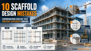
10 Common Scaffold Design Mistakes and How to Avoid Them
Explains common design errors; this article focuses instead on how to review a drawing set before issue.
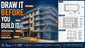
How to Create a Scaffold Drawing: Step-by-Step Design Workflow
Covers creation of the drawing; the present article focuses on the final review stage.
How to Review Scaffold Drawings for Site Constructability
The logical next step after checking drawing completeness and consistency is to review whether the proposed arrangement can actually be constructed under site conditions.
Scaffold Drawing Revisions: How to Manage Changes Without Creating Site Errors
This guide examines revision control and change propagation in more detail.
Key Takeaways
- Do not review a scaffold plan, elevation or section as an isolated drawing.
- Check whether the complete drawing set communicates one consistent scaffold arrangement.
- Confirm that ties, bracing, platforms, bases and other structural requirements shown on the drawing correspond with the current design information.
- After a design change, check every affected plan, elevation, section, detail and associated quantity document.
- A tie or other component can look correct on a drawing but still conflict with the actual building or site condition.
- A pre-issue checklist improves drawing coordination but does not replace structural design, project requirements, manufacturer guidance or applicable regulations.
- The most useful final question is simple: Does every part of this drawing set describe the same scaffold?
Conclusion
A good scaffold drawing review is not simply a search for missing dimensions.
It is a final coordination check between the scaffold geometry, building, site conditions, structural requirements and every drawing used to communicate the design.
Plan, elevation, section and detail should tell the same story.
When a change is made, that story must change consistently everywhere it is affected.
The checklist on this page can serve as a practical starting point for that review. The next useful step is to examine site constructability—whether the coordinated design shown on the drawings can actually be assembled around the real building and site constraints.
Official References
UK Health and Safety Executive — Scaffolds
Authority: Health and Safety Executive
Jurisdiction: Great Britain
Used for: General access scaffold design information, including scaffold configuration, loading, tie requirements and additional scaffold elements.
HSE — Scaffolds
UK Health and Safety Executive — Temporary Works
Authority: Health and Safety Executive
Jurisdiction: Great Britain
Used for: The general requirement that temporary structures withstand foreseeable loads and are used for their intended purpose.
HSE — Temporary Works
OSHA — 29 CFR 1926.451 General Requirements
Authority: Occupational Safety and Health Administration
Jurisdiction: United States
Used for: Scaffold design, capacity, platform construction, access, stability and fall-protection requirements under US federal construction regulations.
OSHA — 29 CFR 1926.451
Last Verified
Last Verified: September 2026
Regulations, official guidance and manufacturer documentation may change. Always confirm the current requirements applicable to the project location, scaffold system and intended use.
This article is general technical information and is not a substitute for project-specific engineering, applicable law, contract documents, project specifications, manufacturer instructions or competent professional review.
About the Author
ISHIDA DESIGN OFFICE brings more than 30 years of practical experience in Japan, specializing in scaffolding design, temporary works planning, CAD drafting, quantity estimation, and construction support.
Drawing on experience from residential, commercial, and industrial projects, he shares practical insights that emphasize not only sound engineering design but also buildability, safety, and real-world jobsite application.
At Scaffold Design Hub, he combines practical experience from Japan with official guidance and technical resources from government agencies, manufacturers, and industry organizations around the world to provide reliable, practical information for construction professionals.
To learn more, visit the About page. For questions or project inquiries, please use the Contact page.