A scaffold drawing can look clean, complete and technically organised while still containing details that become problems when the scaffold reaches the site.
The difficult details are not always the largest or most complicated parts of the scaffold. They are often small differences between the drawing and reality: a building line that changes on an upper floor, a ground level that is not what the available drawings suggested, an entrance that must remain usable, a pipe that occupies the intended scaffold position, or a reference point interpreted differently during erection.
These details matter because a scaffold is not simply a pattern of standards, ledgers, platforms and ties drawn around a building. It has to work with the actual building, actual ground, actual components, actual work activities and actual site constraints.
Having worked in scaffold and temporary works design since 1998, I have learned that drawing review needs to go beyond asking whether the CAD geometry looks correct.
Does the scaffold shown on the drawing correspond with the conditions that will actually exist on site?
1. Changes in Building Geometry Between Floors
One of the easiest mistakes is to understand the building primarily from one floor plan.
Buildings do not necessarily maintain the same external line at every level. Upper floors may step back, project outward, include balconies or canopies, or have completely different relationships with the scaffold.
A scaffold arrangement that looks straightforward at one level may therefore become difficult at another.
Do Not Assume One Floor Represents the Whole Building
When I review information for a scaffold drawing, changes between floor plans deserve particular attention.
A small recess on one floor may affect the working distance. A projection may interfere with a standard or platform. A balcony may change both the horizontal and vertical relationship between the scaffold and the working face.
The important point is not simply to identify that the building has an irregular shape. It is to understand that the scaffold-building interface may change as the scaffold rises.
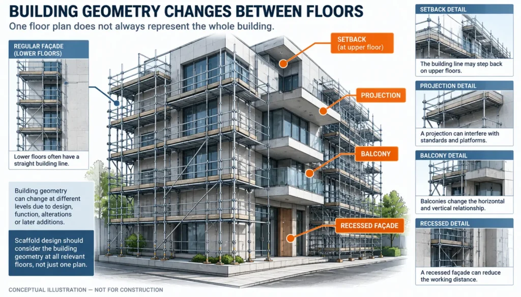
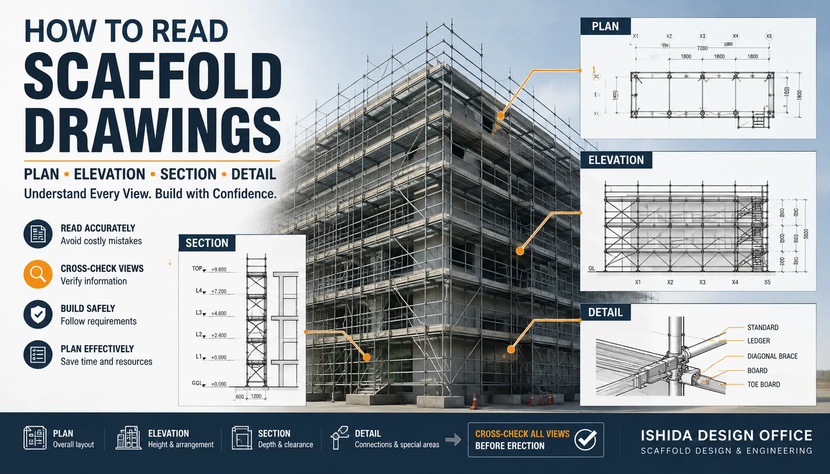
This is why plan, elevation and section information should be read together rather than independently.
Alterations and Existing Conditions Matter
There is another complication: the building on site may not exactly match the drawings being used for planning.
Alterations, extensions and later additions can change the geometry significantly.
A drawing may accurately represent the information originally provided and still fail to represent the building as it exists today.
Where existing conditions are important to the scaffold arrangement, current site information becomes part of the design problem.
2. Ground Levels That Do Not Match the Information Used for Design
On an elevation drawing, the ground may appear as a single reference line. On site, that line can conceal changes in level that affect the scaffold arrangement.
The ground can rise, fall, step or change around the perimeter of a building. Finished levels may also differ from information available during the drawing stage.
Safe Work Australia guidance identifies foundations, ground conditions and the load-bearing capacity of the supporting surface among the matters that should be considered in scaffolding work. These are Australian guidance considerations and should not be treated as universal requirements.
A First-Hand Lesson from Practice
In one project I worked on, the ground conditions encountered on site differed significantly from the information used to prepare my scaffold drawing.
The drawing was consistent with the reference information available at the time. The problem was the difference between that information and the conditions actually present on site. This is why I do not regard a tidy elevation as confirmation that the ground geometry has been established.
A dimensionally clean drawing is not evidence that the site itself is equally regular.
Ground conditions therefore deserve attention not only as a foundation issue but also as a geometry and coordination issue.
This article does not attempt to explain how uneven ground should be structurally resolved. That depends on the scaffold system, site conditions, supporting surface, applicable requirements and engineering design.
The first task is simpler: identify the discrepancy before assuming that the drawing can be erected exactly as shown.
For a deeper discussion of support conditions, see Scaffold Base Design: Base Plates, Sole Boards and Ground Conditions.
3. The Reference Point Used on the Drawing and the Starting Point Used on Site
A less obvious problem is the relationship between the drawing reference and the point from which erection actually begins.
A difference in reference points may appear minor when reviewing a single bay, but its effect can become clearer across the full scaffold arrangement.
I have experienced a case where the scaffold drawing was arranged from one reference point, while erection on site effectively began from a different point. As the scaffold progressed, the difference accumulated and the physical arrangement increasingly failed to correspond with the drawing.
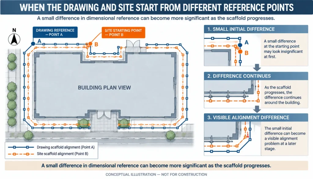
I do not take this experience to mean that every scaffold should be erected from a prescribed starting point. The important issue is whether the drawing and the site arrangement use compatible references.
DRAWING CHECK: The dimensional logic of the drawing and the dimensional logic being followed on site need to correspond. If they do not, a small initial difference can become a much more visible problem farther around the building.
This is the type of issue that can be difficult to recognise by looking only at individual scaffold bays. The complete arrangement has to be considered.
4. The Distance Between the Scaffold and the Building
The relationship between the inside edge of the scaffold and the working face is another detail that deserves careful review.
It is tempting to think of this as one dimension repeated around the building.
Real façades rarely behave that simply.
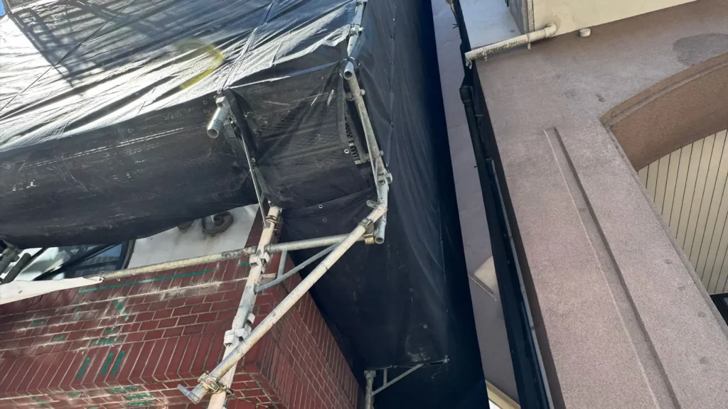
Columns, balconies, recesses, projections, architectural finishes and other features can change the effective working face.
Check the Actual Working Face
The relevant question is not simply:
What distance was drawn between the scaffold and the building line?
It is also:
What will the worker actually be facing at this location?
The answer may change along the same elevation.
For example, the structural line shown on one drawing may not represent the final external surface at every location. A façade finish, projection or local feature may change the practical relationship between the platform and the work.
Requirements also vary by jurisdiction. In the United States, for example, OSHA 29 CFR 1926.451 contains specific platform and working-face provisions, including conditions and exceptions. Those U.S. requirements should not be treated as universal dimensions for projects elsewhere.
The applicable local requirements, scaffold system, work activity and project conditions should always be checked.
Projections and Recesses Change the Relationship
A scaffold line that appears regular in plan can interact with an irregular building in very different ways at different locations.
That is why the distance from the building should not be treated as an isolated dimension.
It is part of the scaffold-building interface.
5. Openings Are More Than Empty Spaces on a Plan
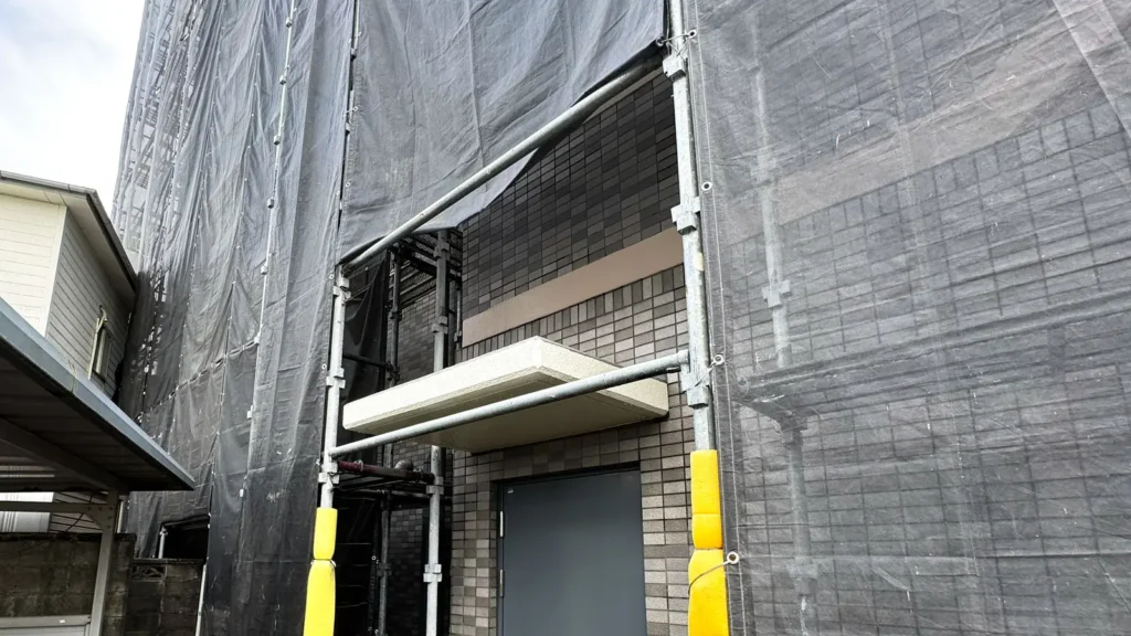
Doors, entrances and other openings often appear as simple gaps in architectural drawings.
For scaffold planning, they can affect much more than geometry.
An opening may be part of a worker route, building access, material movement or another activity that needs to continue while the scaffold is present.
Worker Movement Matters
A scaffold arrangement should not be reviewed only as a static structure.
People need to use it.
When looking at openings, I therefore consider whether the proposed arrangement has properly accounted for how workers will move through the scaffold and how the relevant area will be used.
Safe access is also identified as a design consideration in Safe Work Australia guidance, while OSHA has jurisdiction-specific requirements governing scaffold access in the United States.
The exact solution depends on the project and applicable requirements.
The important drawing-review question is whether access has actually been considered rather than merely whether an opening has been drawn.
Entrances and Access Routes Need Context
A doorway on a plan tells you that a door exists.
It does not necessarily tell you:
- how frequently it is used;
- whether workers or the public need to pass through it;
- whether materials need to move through it;
- what vertical clearance is required;
- what temporary conditions may exist during construction.
That additional context can change the scaffold planning problem.
For a detailed discussion, see Scaffold Openings and Obstructions: How to Plan Around Real Site Conditions.
6. Pipes, Canopies, Glass, Drains and Other Easily Missed Site Conditions
Architectural and structural drawings are essential sources of information, but they do not necessarily show every condition relevant to a scaffold.
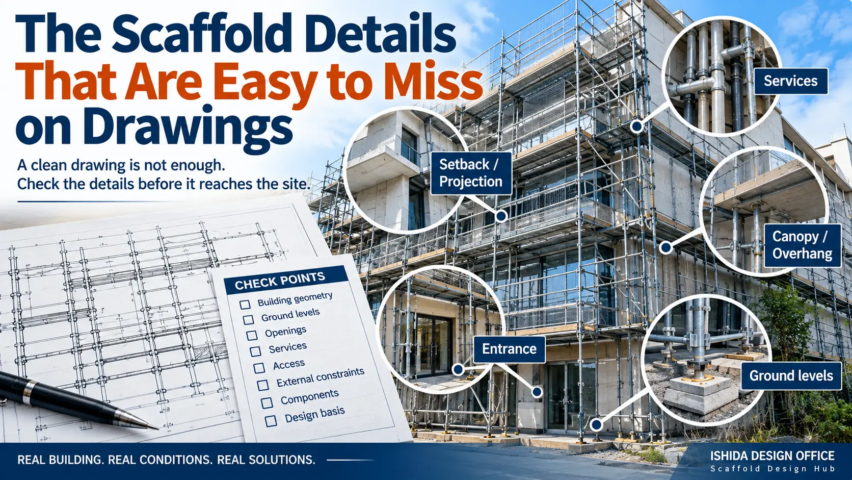
In practice, some of the details that require attention include:
- service pipes;
- canopies;
- glazing;
- drainage channels;
- changes in ground level;
- external finishes;
- loading or delivery entrances;
- existing equipment;
- later building alterations.
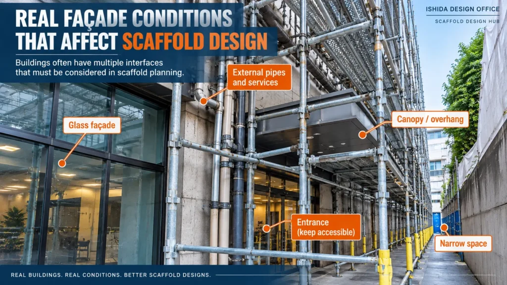
Any one of these may occupy space that looked available when the scaffold was first considered.
Architectural Drawings Do Not Always Tell the Whole Story
This does not mean architectural drawings are unreliable.
It means they were created for purposes that are not necessarily identical to scaffold planning.
The scaffold designer may therefore need information from several sources to understand the interface properly.
That can include plans, elevations, sections, site information, photographs and project-specific information.
Photographs Help, but They Are Not Always Enough
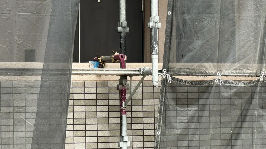
Site photographs can reveal conditions that are difficult to understand from drawings.
They are particularly useful for seeing façade features, services, existing structures and restricted areas.
But photographs also have limitations.
A photograph may hide depth, dimensions, level differences or objects outside the camera angle. A condition that looks clear from one viewpoint may be very different when considered in three dimensions.
Photographs should therefore be treated as useful evidence, not as an automatic substitute for the dimensional information required for design.
7. Ground Conditions, Boundaries and External Constraints
Some important scaffold details are not part of the scaffold or the building.
They are around them.
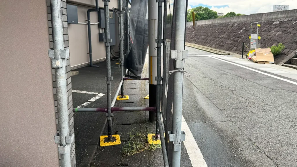
Property boundaries, roads, adjacent structures, overhead electrical lines, poles and other site features can limit where a scaffold can physically be placed.
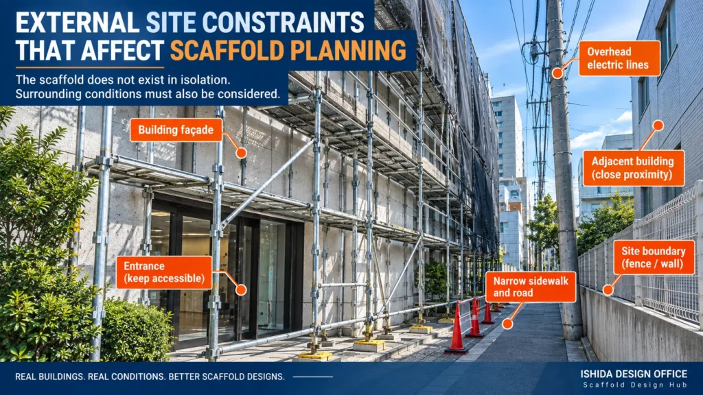
Safe Work Australia guidance identifies electrocution from work near power lines among the risks associated with scaffolding work and provides separate guidance concerning scaffolding work near overhead electric lines.
Site Boundaries
A CAD model gives the designer an almost unlimited drawing space.
A construction site does not.
The available area may end at a property boundary, roadway, neighbouring structure or another restricted zone.
A scaffold that fits around the building geometrically may therefore still fail to fit within the space actually available for the work.
Boundary information should consequently be treated as a real design constraint rather than background information.
Power Lines, Poles and Other External Features
Electrical infrastructure requires particular attention because it introduces hazards that cannot be resolved simply by moving a line on a scaffold drawing.
The relevant authority requirements, utility requirements and project controls need to be identified for the jurisdiction and site concerned.
IMPORTANT: Do not stop reviewing at the outside edge of the scaffold. The surrounding environment is part of the scaffold planning problem.
8. CAD Geometry Is Not the Same as Understanding Scaffold Components
Modern CAD makes it possible to produce extremely clean drawings.
That is valuable.
But the ability to draw a scaffold and the ability to understand a scaffold are not the same skill.
A line in CAD has almost no physical consequences. A real scaffold component has dimensions, connections, orientation and limitations.
If the person preparing the drawing does not understand how the actual components relate to one another, interfaces can be difficult to evaluate properly.
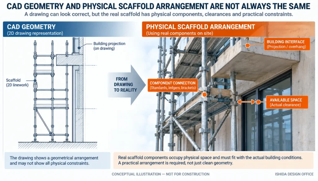
Knowing the Components Changes How You Read the Drawing
This becomes especially important where several conditions meet:
- a change in building geometry;
- an opening;
- a projection;
- an access route;
- a change in level;
- a tie location;
- another scaffold component.
The question is no longer simply whether the lines intersect correctly.
The question becomes whether the physical components can form the arrangement represented by those lines.
This is one reason scaffold drawing should not be treated as CAD drafting alone.
A useful drawing represents a buildable physical arrangement, not just clean geometry.
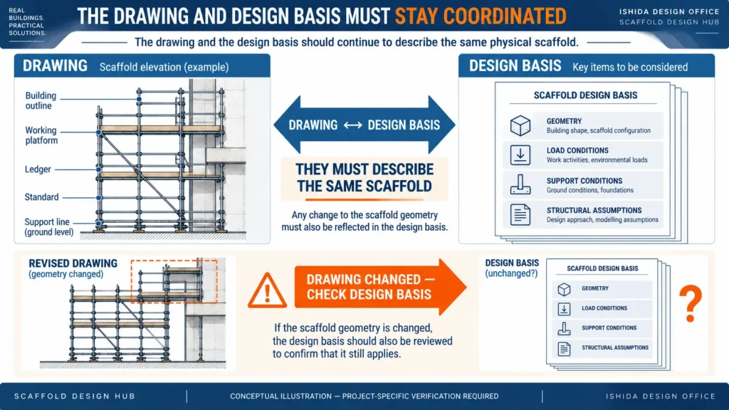
9. The Drawing and Structural Verification Must Describe the Same Scaffold
Another easy-to-miss issue appears when the drawing and the structural verification gradually become two separate documents.
A calculation may be based on a particular scaffold arrangement, loading condition, support condition or structural assumption.
If the drawing changes, the relevant design basis needs to remain consistent with what is actually being shown.
In the United States, OSHA 29 CFR 1926.451 states that scaffolds must be designed by a qualified person and constructed and loaded in accordance with that design. In Great Britain, HSE scaffold design guidance explains that scaffolds outside a recognised standard configuration require bespoke calculation by a competent person, and it identifies project information needed for an accurate design process. These are jurisdiction-specific examples rather than universal rules.
DRAWING CHECK: The drawing should not represent one scaffold while the structural verification is effectively checking another.
This article deliberately does not explain calculation procedures or internal calculation-review methods. That subject deserves separate treatment.
Field Experience: Why One Drawing Revision Can Affect the Entire Drawing Set
In my scaffold drawing work in Japan, revisions to one drawing often require changes to several related documents.
For example, when a scaffold arrangement is modified on the plan, the corresponding elevation, section, details and material quantities may also need to be reviewed.
This is not an unusual situation in practical drawing work. A single correction can affect multiple parts of the drawing set.
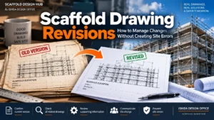
For this reason, I do not consider a revision complete simply because the original drawing has been corrected. I also check which other drawings and documents may be affected by that change.
My practical rule is simple: A drawing revision is not complete until its effects on the related drawings and documents have been checked.
This is one of the most important lessons I have learned from working with scaffold drawings since 1998.
10. Experience Changes What You Notice
Experience has changed my drawing reviews less by making the CAD work faster than by changing which uncertainties I notice in the information supplied.
Before developing a scaffold arrangement, I try to form a mental picture of the scaffold as a complete three-dimensional structure rather than seeing it only as separate plan and elevation lines.
That perspective has developed through repeated drawing work, not through CAD proficiency alone.
Understanding the scaffold components also matters. Without knowing how the components actually relate to one another, it is difficult to understand complicated interfaces simply from CAD geometry.
The same applies to regulations, project requirements, manufacturer instructions and structural design information. Drawing skill cannot replace the need to understand the conditions that govern the scaffold.
Experience does not eliminate mistakes. It does, however, change the questions I ask when checking the available information.
Instead of asking only:
Can I draw the scaffold here?
the review gradually becomes:
Does this arrangement make sense as a complete scaffold under the actual conditions of this project?
That distinction is at the heart of detailed scaffold drawing review.
A Practical Easy-to-Miss Detail Review
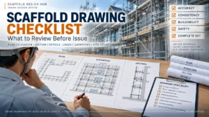
This is not intended to replace a formal design review or the full Scaffold Drawing Checklist: What to Review Before Issue.
It is a short prompt for conditions that can disappear when attention is focused too heavily on the main scaffold geometry.
| Review Area | Question to Ask |
|---|---|
| Floor geometry | Does the building line change between levels? |
| Existing building | Does current site information match the drawings being used? |
| Ground | Are levels and supporting conditions understood? |
| Reference geometry | Is the site arrangement based on the same dimensional logic as the drawing? |
| Building interface | Does the working face change because of recesses or projections? |
| Openings | Has actual use and movement around the opening been considered? |
| Services | Are pipes, equipment and other services affecting the scaffold space? |
| Access | Can workers reach and move through the required work areas? |
| External constraints | Are boundaries, roads, neighbouring structures, poles or electrical lines relevant? |
| Components | Does the arrangement make sense with the actual scaffold components? |
| Structural verification | Does the design basis correspond with the scaffold shown? |
| Information quality | Is additional site information needed before the drawing is finalised? |
If several answers are uncertain, the solution is not to make the CAD drawing look more complete.
The missing information should be identified. That is often the more valuable outcome of a drawing review.
FAQ
What scaffold drawing details are most commonly overlooked?
There is no universal list because the critical details depend on the building, scaffold system, work activity and site. However, changes in building geometry, ground levels, openings, working-face distance, services, access routes, boundaries and other site constraints deserve particular attention because they can be understated in simplified drawings.
Can a scaffold drawing be technically correct but still be difficult to build?
Yes. A drawing may be internally consistent while relying on building geometry, ground conditions or site information that differs from actual conditions. Constructability should therefore be considered separately from CAD accuracy.
Are site photographs enough to prepare a scaffold drawing?
Photographs are valuable for understanding existing conditions, but they do not necessarily provide reliable dimensions, depth, hidden conditions or complete coverage. They should be used together with the other project information needed for the design.
Why is the scaffold starting or reference point important?
If the dimensional reference used on the drawing differs from the logic followed during erection, differences can accumulate as the scaffold progresses. The drawing and site need a consistent dimensional basis.
Should calculations and scaffold drawings be reviewed together?
Where structural verification is required, the arrangement and relevant design assumptions need to remain coordinated. Exact responsibilities and requirements depend on the jurisdiction, scaffold system, project and applicable documentation.
Does knowing CAD make someone a scaffold designer?
CAD proficiency is valuable for producing drawings, but scaffold design also requires understanding the physical system, interfaces, site conditions and applicable technical requirements. CAD is a tool for representing the design; it is not the entire design process.
Related Topics
- Scaffold Drawing Checklist: What to Review Before Issue — a broader pre-issue review framework.
- How to Review Scaffold Drawings for Site Constructability — a deeper look at whether the proposed scaffold can actually be erected on site.
- Scaffold Openings and Obstructions: How to Plan Around Real Site Conditions — more detail on openings, access and site obstructions.
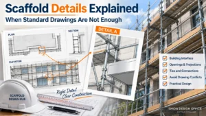
- Scaffold Details Explained: When Standard Drawings Are Not Enough — when additional detail drawings become necessary.
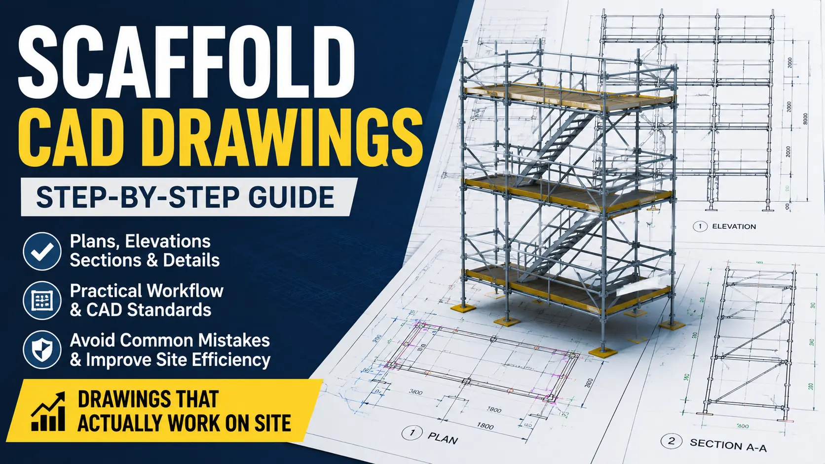
- How to Create a Scaffold Drawing: Step-by-Step Design Workflow — the broader scaffold drawing workflow.
Key Takeaways
- A clean CAD drawing can still fail to represent actual site conditions.
- Building geometry should be understood across floors rather than from one plan alone.
- Differences in ground conditions or dimensional reference points can create significant alignment problems.
- Openings, access, services, boundaries and external infrastructure are part of the scaffold planning problem.
- Site photographs are valuable, but they do not automatically provide all the dimensional and three-dimensional information needed.
- Understanding real scaffold components is different from simply drawing their geometry.
- Where structural verification is required, the scaffold represented by the drawing needs to remain consistent with the relevant design basis.
Conclusion
The two situations I have described—ground conditions differing from the drawing information and a site starting point differing from the drawing reference—show why apparently minor assumptions deserve attention. Other interfaces, including openings, services and building projections, need the same care.
The practical lesson is to look beyond whether the drawing itself is neat and complete. The building, site, scaffold components, work requirements and relevant design information need to describe the same physical reality.
The natural next question is not simply “What else should be on the drawing?”
It is:
“When I first receive or review a scaffold drawing, what should I look at first?”
That question will be addressed separately in What I Check First When Reviewing a Scaffold Design.
Official References
The following official sources were used in preparing and verifying this article.
- Occupational Safety and Health Administration (OSHA), United States — 29 CFR 1926.451, General Requirements for Scaffolds. Used for U.S.-specific statements concerning scaffold design, platform and working-face provisions, and access requirements. OSHA 29 CFR 1926.451
- Health and Safety Executive (HSE), Great Britain — Scaffolds / Scaffold Design. Used for the distinction between recognised standard configurations and scaffolds requiring bespoke calculation, and for scaffold design-input information. HSE Scaffold Design Guidance
- Safe Work Australia — Scaffolds and Scaffolding Work General Guide. Used for guidance concerning ground conditions, foundations, access and other scaffolding-work considerations. Safe Work Australia Scaffolding Guidance
- Safe Work Australia — Scaffolding Work Near Overhead Electric Lines Information Sheet. Used for guidance concerning scaffolding work near overhead electric lines. Safe Work Australia — Overhead Electric Lines
Last Verified
Last Verified: September 2026
Regulations, official guidance and manufacturer documentation may change. Always confirm the current requirements applicable to the project location, scaffold system and intended use.
This article is general technical information and is not a substitute for project-specific engineering, applicable law, contract documents, project specifications, manufacturer instructions or competent professional review.
About the Author
ISHIDA DESIGN OFFICE brings more than 30 years of practical experience in Japan, specializing in scaffolding design, temporary works planning, CAD drafting, quantity estimation, and construction support.
Drawing on experience from residential, commercial, and industrial projects, he shares practical insights that emphasize not only sound engineering design but also buildability, safety, and real-world jobsite application.
At Scaffold Design Hub, he combines practical experience from Japan with official guidance and technical resources from government agencies, manufacturers, and industry organizations around the world to provide reliable, practical information for construction professionals.
To learn more, visit the About page. For questions or project inquiries, please use thethe Contact page.