If you work with scaffold drawings regularly, the words plan, elevation, and section probably sound basic.
But basic does not mean unimportant.
I have worked with scaffold and temporary works drawings for more than 30 years, and one lesson has stayed with me:
Many drawing problems do not begin with complicated engineering. They begin when someone looks at only one view and assumes they understand the whole scaffold.
A plan can look correct while hiding a vertical problem.
An elevation can look clean while hiding a clearance problem.
And a section can work perfectly at one location while telling you very little about what happens around the next corner.
The simplest way I explain the difference is:
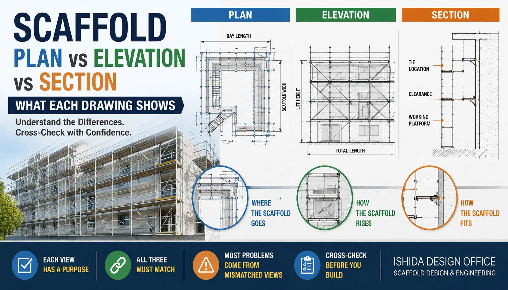
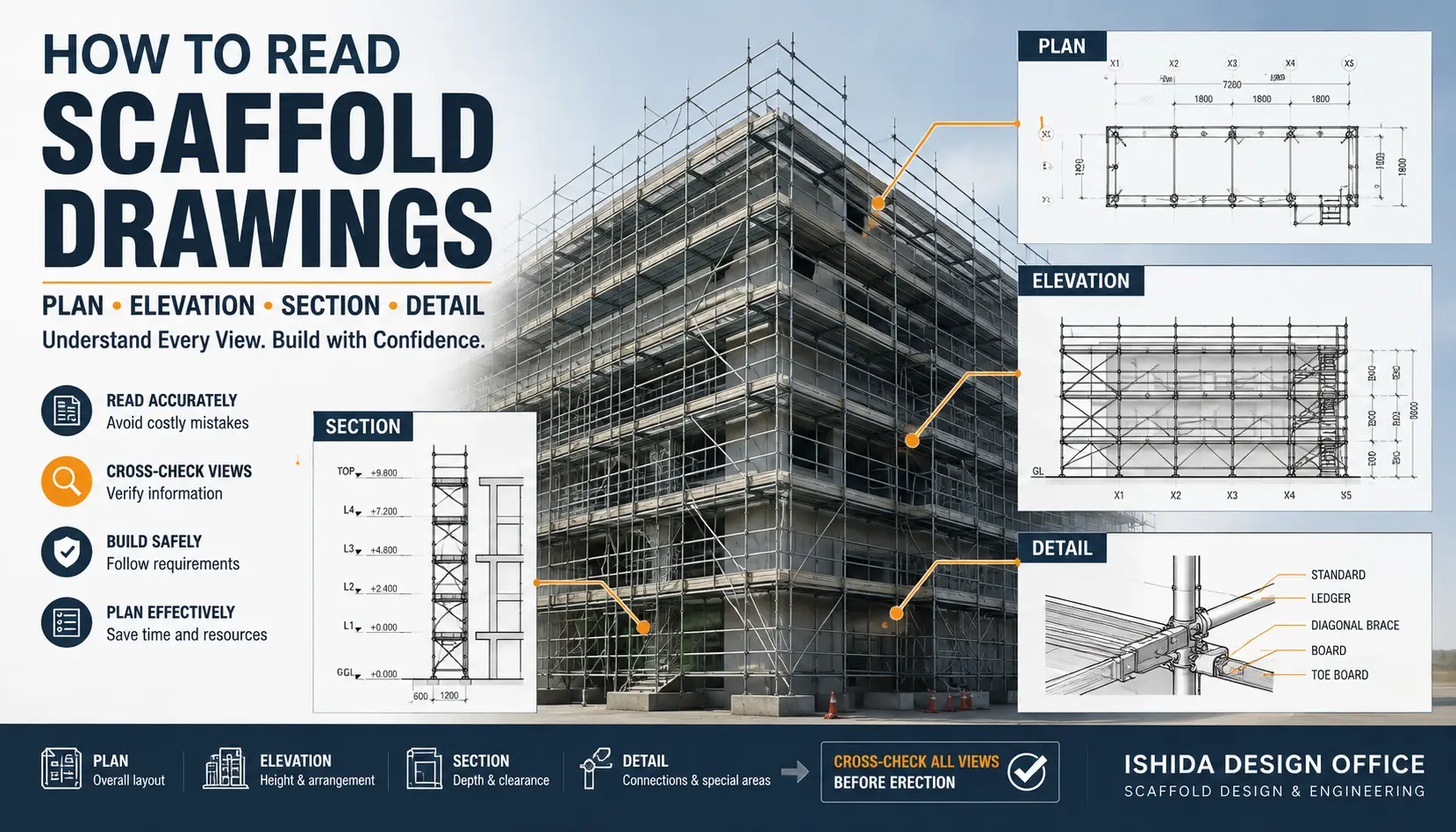
- Plan = where the scaffold goes
- Elevation = how the scaffold rises
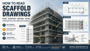
- Section = how the scaffold fits against the building
But the real skill is not memorising those definitions.
It is learning to read the same scaffold through all three views.
That is what this guide is about.
Practical Tip: If you want to understand how a complete scaffold drawing set fits together before focusing on these three views, see How to Read Scaffold Drawings.
Why Plan, Elevation and Section Matter on a Real Scaffold Project
A scaffold drawing is more than a picture of standards, ledgers and platforms. It is a communication tool between designers, scaffold contractors, supervisors, engineers and the people who will actually work around the scaffold.
In my drawing work, I do not only ask whether the drawing looks neat on the screen.
I ask:
Can the person using this drawing understand what is supposed to happen on site?
That is a much more important question.
A drawing can contain individually correct lines and still fail as a coordinated drawing.
For example:
- the plan shows one bay arrangement while the elevation shows another
- an entrance appears on the plan but is ignored in the elevation
- a balcony appears in the section but is not reflected in the scaffold layout
- a tie looks reasonable in elevation but conflicts with an opening
- diagonal bracing interferes with access
- one view belongs to a different revision
These may look like small CAD problems.
On site, they can become:
- additional labour
- additional materials
- delayed erection
- redesign
- lost access
- coordination problems
- unsafe improvisation
- avoidable cost
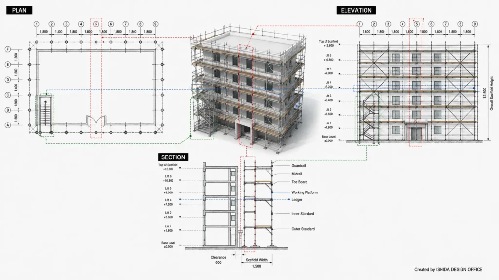
That is why I prefer to think of plan, elevation and section as:
Key Idea: One scaffold shown from three directions.
Scaffold Plan Drawing — Looking at the Scaffold from Above
A scaffold plan shows the horizontal relationship between the scaffold, building and surrounding site. It is usually the best view for understanding the overall footprint before concentrating on height.
Think of yourself above the building, looking straight down.
What a Scaffold Plan May Show
Depending on the project, a scaffold plan may include:
- building footprint
- façade line
- inner and outer scaffold standards
- bay arrangement
- bay lengths
- scaffold width
- façade offset
- corners
- returns
- entrances
- stair towers
- ladder access
- loading bays
- pedestrian routes
- restricted areas
- openings
- projecting structures
- grid lines
- key dimensions
- section callouts
- elevation references
- north arrow where relevant
Not every project requires every item.
The purpose of the drawing is not to fill empty space with information.
The purpose is to communicate what the people using the drawing need to understand.
What I Check First on a Scaffold Plan
When I review a plan, I do not begin by inspecting every scaffold component.
I look at the building first.
Where does the façade turn?
Where does it move inward or outward?
Where are the entrances?
Where are the narrow areas?
Where do workers, occupants, materials or vehicles need to pass?
Only after I understand the building do I concentrate on the scaffold.
That sequence matters.
A scaffold should respond to the actual building and actual work.
The building should not be forced into an idealised rectangular scaffold grid.
How Bay Arrangement Appears on the Plan
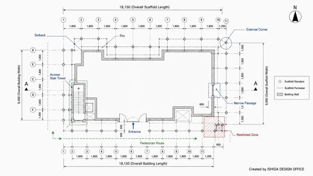
One of the most useful things a plan communicates is the bay arrangement.
A long elevation may look simple.
But the plan may reveal:
- a short final bay
- an irregular corner
- a setback
- a narrow passage
- a doorway
- a scaffold return
- a stair tower
- a loading area
Those conditions often influence other parts of the design.
Common English Names for Scaffold Plan Drawings
Depending on the contractor, designer or country, you may see terms such as:
- Scaffold Plan
- Scaffold Layout
- Scaffold Layout Plan
- General Arrangement Plan
- GA Plan
The terminology varies.
Do not judge the drawing only by its title.
Ask:
What information is this view intended to communicate?
Scaffold Elevation Drawing — Understanding Height and Vertical Arrangement
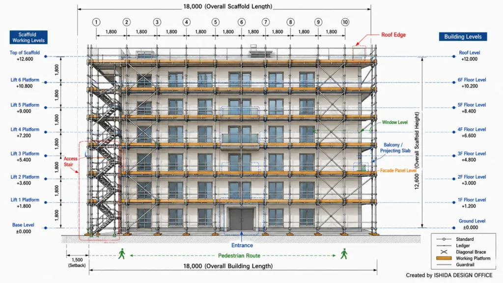
An elevation shows the scaffold vertically from the front or side. This is usually the easiest view for understanding lifts, working levels, bracing, ties and the relationship between the scaffold and building floors.
If the plan answers “Where?”, the elevation answers:
“How high, and what happens vertically?”
What a Scaffold Elevation May Show
A scaffold elevation may include:
- overall height
- lift heights
- working platform levels
- standards
- ledgers
- guardrails
- toe boards where applicable
- diagonal bracing
- façade bracing
- scaffold ties
- stairs
- openings
- bridges
- loading bays
- floor levels
- roof level
- changes in building height
- temporary protection where applicable
- vertical dimensions
How Building Levels Relate to the Scaffold Elevation
I pay particular attention to the relationship between scaffold lifts and the building.
A scaffold does not exist simply to form a neat geometric frame.
Someone has to work from it.
The working platforms therefore need to make sense in relation to the work area, which might include:
- windows
- façade panels
- roof edges
- balconies
- slabs
- cladding
- painting areas
- inspection zones
A visually regular elevation is not automatically a useful working scaffold.
How Bracing and Ties Appear on an Elevation
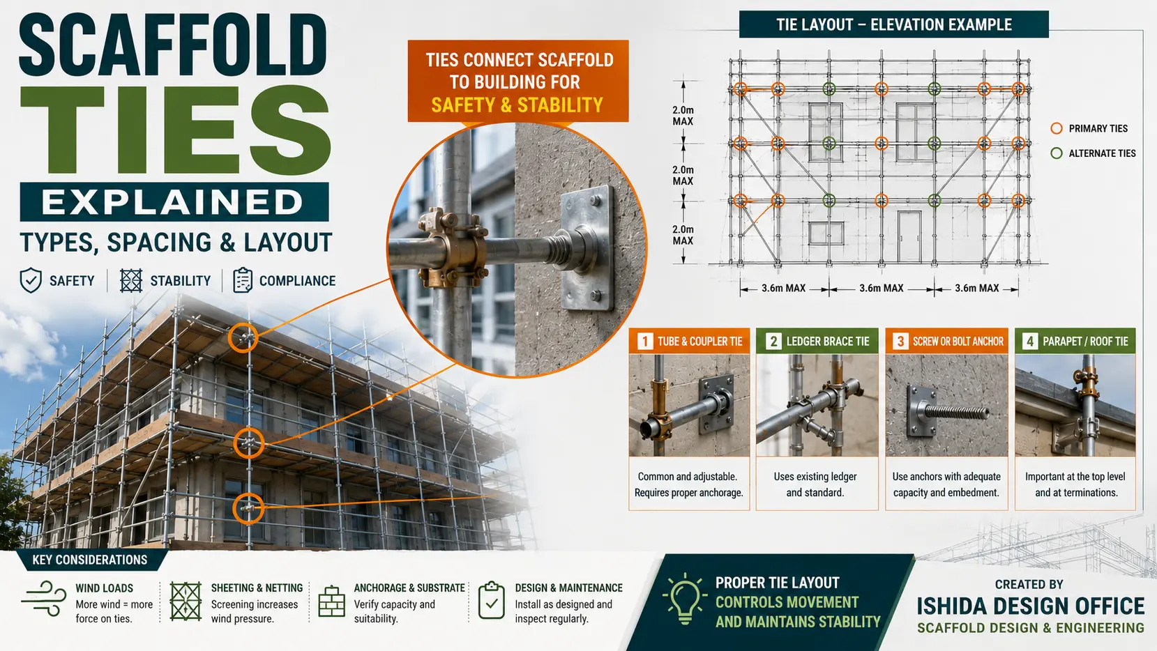
Elevation drawings are also very useful for understanding the intended bracing and tie layout.
However, there is an important limitation.
DRAWING CHECK: A tie symbol shown on an elevation does not prove that a suitable anchorage exists at exactly that physical location. Always ask: What is behind the symbol?
The building could contain:
- glazing
- an opening
- a void
- a weak or unsuitable substrate
- another architectural feature
This is where the plan, section, detail or structural information becomes important.
One view alone rarely tells the complete story.
If you need to go deeper into these two elements, continue with Scaffold Bracing Explained and Scaffold Ties Explained: Types, Spacing & Layout.
Scaffold Section Drawing — Understanding Width, Clearance and Interfaces
A scaffold section cuts vertically through the scaffold and building. It is often the view that reveals why an apparently simple scaffold is not simple at all.
Plan gives location.
Elevation gives height.
Section gives depth and relationship.
What a Scaffold Section May Show
Depending on the project, the section may include:
- building wall
- inside standard
- outside standard
- scaffold width
- working platform
- inside platform or bracket
- façade clearance
- guardrails
- toe boards
- floor slab
- parapet
- balcony
- canopy
- roof edge
- projecting sill
- base plate
- base or foundation condition
- tie relationship
- brackets
- overhead obstructions
The practical question behind the section is:
Can the scaffold actually fit here and still do the job?
Why the Section Can Reveal Hidden Problems
Imagine that the plan is straight.
Nothing looks unusual.
The elevation is also regular.
Then you look at the section.
A balcony projects into the scaffold zone.
Now the problem becomes visible.
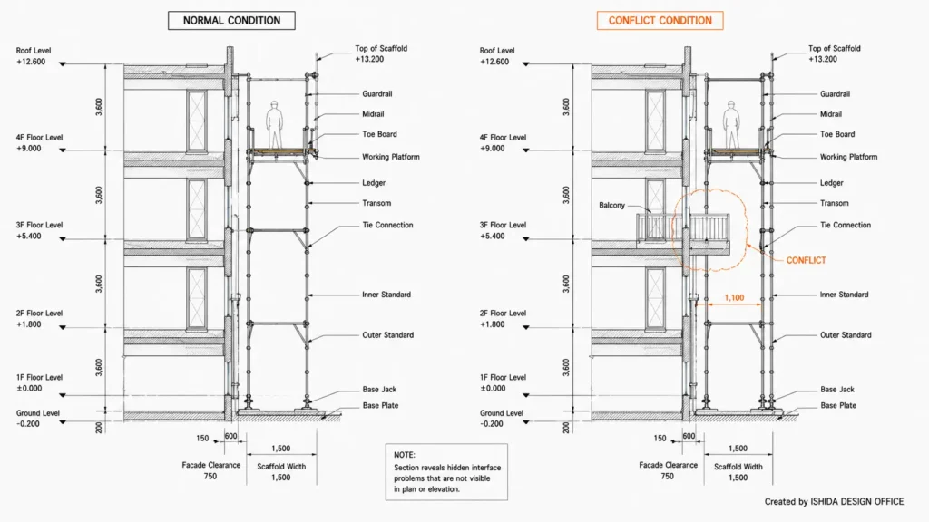
Depending on the scaffold system and project-specific design, that condition may affect:
- scaffold width
- standard position
- platform layout
- inside boards
- brackets
- bridging
- ties
- loading
- erection sequence
- engineering requirements
A relatively small section drawing can therefore explain a large site problem before erection starts.
A Section Is Location-Specific
This is another point that is easy to overlook.
One section does not necessarily represent the entire building.
A building may need different sections at:
- normal façade
- balcony
- entrance canopy
- roof
- setback
- loading bay
- projecting architecture
Whenever I see the words Typical Section, I still ask:
Where does the typical condition stop being typical?
That is a useful question on almost any project.
Scaffold Plan vs Elevation vs Section — Quick Comparison
The three views describe the same three-dimensional scaffold from different directions. Understanding the main question answered by each view makes drawing review much faster.
| Drawing | View Direction | Main Purpose | Typical Information | Main Question |
|---|---|---|---|---|
| Plan | From above | Horizontal layout | Bays, footprint, corners, access | Where is it? |
| Elevation | From front or side | Vertical arrangement | Lifts, platforms, braces, ties | How high is it? |
| Section | Cut through scaffold | Depth and interface | Width, clearance, building relationship | How does it fit? |
You can also think about the three views through the X, Y and Z axes:
- Plan = X + Y
- Elevation = X + Z
- Section = Y + Z
Together, the drawings allow you to reconstruct the scaffold mentally in three dimensions.
That is the real objective.
You should not simply see three separate technical drawings.
You should begin to see the scaffold in your head.
Once the three views make sense, the next step is understanding the dimensions you are checking in each one. See Scaffold Dimensions Explained: Bay Length, Lift Height, Width & Standards.
How I Cross-Check Plan, Elevation and Section
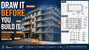
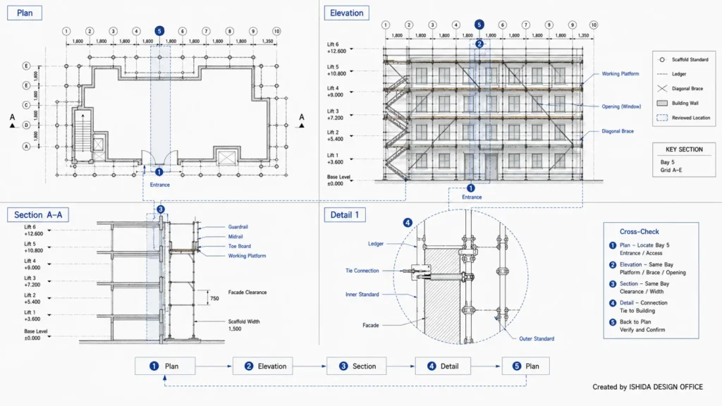
One of the most useful habits in scaffold drawing review is to choose a physical location and follow that same location through every relevant view.
I find this much more reliable than randomly moving around a crowded drawing sheet.
Step 1 — Check the Drawing Information
Before looking closely at the scaffold, check:
- project
- drawing number
- revision
- drawing status
- issue date
- designer
- checker where applicable
- scale
- relevant notes
A technically good drawing can still cause problems if someone is looking at the wrong revision.
Step 2 — Understand the Plan
Identify:
- building geometry
- scaffold footprint
- bay layout
- corners
- returns
- entrances
- access
- stairs
- loading areas
- unusual locations
First understand where the scaffold goes.
Step 3 — Follow the Same Area into the Elevation
Now check:
- lift arrangement
- platforms
- ties
- bracing
- building openings
- access
- roof
- vertical changes
Ask:
Is this the same scaffold that I just understood in plan?
Step 4 — Find the Relevant Section
Check:
- scaffold width
- façade clearance
- platform position
- building projections
- brackets
- base condition
- special geometry
Step 5 — Read Details and Notes
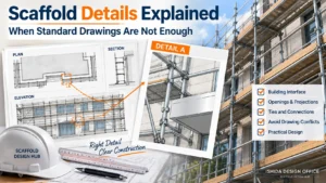
Unusual conditions often need enlarged details.
Look for references such as:
- Detail A
- Detail 1
- Section A–A
- Section B–B
- Typical Detail
- Enlarged Detail
Step 6 — Return to the General Arrangement
Finally, return to the main drawing.
Ask:
Does everything still agree?
For me, drawing review is not a straight line.
It is a cycle:
Plan → Elevation → Section → Detail → Back to Plan
Japanese Practice Note
My scaffold drawing experience has mainly developed through Japanese construction projects, where the scaffold often has to be coordinated closely with the building, neighbouring properties, pedestrian movement, delivery routes and the actual work sequence.
One practical habit I have carried from that experience is to check the building first and the scaffold second.
Before concentrating on individual scaffold components, I look for changes in the façade, entrances, balconies, roof projections, narrow access zones and other site conditions that may influence the layout.
I also prefer to coordinate the plan, elevation and section before relying heavily on the drawing for material quantities. A small coordination error can become a quantity problem later if materials are taken off from a layout that is not yet fully resolved.
This principle is not uniquely Japanese.
It works anywhere:
The scaffold drawing should reflect the actual building, actual access, actual work and actual site constraints—not an idealised scaffold geometry.
Japanese drawing conventions and construction practices are not identical to those in the US, UK, Australia or other regions.
Requirements vary by country, jurisdiction and project. Always follow local regulations, project specifications and the scaffold manufacturer’s current instructions.
What You May See on English-Language Scaffold Drawings
English-language engineering drawings use terminology that may differ slightly between companies and countries. Understanding several common terms can make a scaffold drawing much easier to navigate.
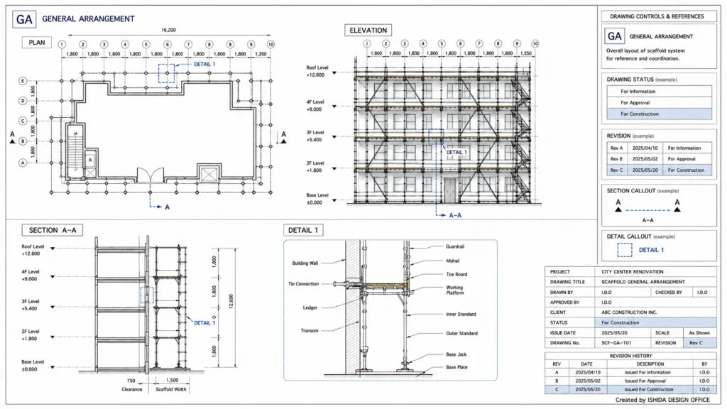
General Arrangement — GA
You may see:
General Arrangement
or simply:
GA
A GA drawing normally communicates the overall intended arrangement.
For scaffold work, a GA drawing package may contain:
- plans
- elevations
- sections
- details
- dimensions
- notes
- references to calculations
- references to other drawings
The GA tells you the overall design intent.
A detail may explain how a particular unusual location is resolved.
Drawing Status
Never ignore the drawing status.
Depending on the company’s document-control system, you may see wording such as:
- Preliminary
- For Information
- For Approval
- For Construction
- As Built
The exact terminology varies between organisations.
That is why the project drawing procedure matters.
A drawing can look complete and still not be authorised for construction.
Revision
Common systems include:
- Rev A
- Rev B
- Rev C
or:
- Rev 01
- Rev 02
- Rev 03
The important thing is not whether the drawing uses letters or numbers.
The important thing is that everyone is using the same current revision.
Section Callout
A section reference may appear as:
A–A
The marker normally tells you:
- where the imaginary cut passes through the drawing
- which direction the section is viewed from
That connection between plan and section is important.
A section without a clearly understood location can easily be misinterpreted.
Detail Callout
A detail enlarges a location that needs more explanation.
Examples may include:
- special tie
- beam arrangement
- bracket
- bridge
- loading bay
- base condition
- roof interface
A simple way to remember the relationship is:
GA = where
Detail = how
What Information Should Appear on a Scaffold Drawing?
There is no single universal drawing layout that applies to every scaffold in every country. The required information depends on the system, project complexity, design scope, manufacturer guidance, contractual requirements and local regulations.
However, a useful working drawing should reduce unnecessary assumptions.
Drawing Control Information
Where appropriate:
- project name
- drawing title
- drawing number
- revision
- drawing status
- issue date
- scale
- designer
- checker
- relevant notes
Geometry and Key Dimensions
The drawing may need to communicate:
- scaffold length
- scaffold height
- scaffold width
- bay arrangement
- lift arrangement
- critical clearances
- changes in geometry
Structural Arrangement
Where relevant:
- standards
- ledgers
- transoms or bearers
- platforms
- braces
- ties
- beams
- brackets
- special components
Access and Work Areas
Depending on scope:
- stair towers
- ladders
- access bays
- loading bays
- working platforms
- pedestrian interfaces
- restricted areas
Building and Site Interfaces
This is an area I do not like to leave vague.
Show enough information to understand the relationship with:
- building façade
- roof
- balconies
- entrances
- ground
- public routes
- plant
- adjacent structures
- other site restrictions
A scaffold does not exist in empty space.
The interfaces are often where the most important coordination problems appear.
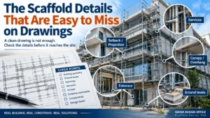
Common Scaffold Drawing Coordination Mistakes
Most of these problems are not dramatic.
That is exactly why they are easy to miss.
A small inconsistency on a drawing can become an expensive inconvenience once erection has started.
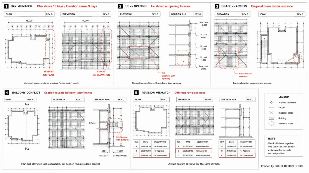
1. Plan and Elevation Have Different Bay Counts
For example:
Plan: 10 bays
Elevation: 9 bays
Do not simply decide which drawing “looks right.”
Find the reason.
Possible causes include:
- revision mismatch
- drafting error
- omitted bay
- changed building geometry
- modified bay layout
2. The Elevation Shows a Tie Where the Building Cannot Accept One
A tie symbol appears on the drawing.
But what is behind it?
At the corresponding location there may be:
- glazing
- an opening
- a void
- an architectural feature
- unsuitable substrate
- another structural restriction
Tie arrangement must be coordinated with the actual building, scaffold system, design requirements and applicable regulations.
3. A Brace Blocks an Entrance
The elevation looks reasonable.
Then you check the plan.
The brace crosses an access point.
This is exactly the type of issue that should be resolved during drawing coordination rather than improvised during erection.
4. A Balcony or Canopy Is Missed
The main façade may be flat.
Then one floor suddenly projects outward.
The elevation may not communicate the problem clearly.
The section usually does.
5. Different Revisions Are Used Together
For example:
Plan: Rev C
Elevation: Rev B
Section: Rev C
REVISION CHECK: The drawings may look almost identical. Almost is not enough. Confirm that the plan, elevation, section and details belong to the same current drawing set before relying on them.
6. One Typical Section Is Used Everywhere
A typical section is useful only while the geometry remains typical.
Once the façade changes, the section may no longer represent the real condition.
7. Too Much Information Is Put on One View
More information does not automatically mean a better drawing.
If every component, note and dimension is crowded onto one view, the important information becomes difficult to find.
Technical drawings need hierarchy.
8. The Scaffold Is Shown but the Building Problem Is Not
This is a conceptual mistake that matters.
A scaffold drawing should not show a scaffold floating in an empty white space.
Include enough of the real building and surroundings to explain why the scaffold is arranged that way.
International Perspective — Drawings Support Compliance, but They Are Not the Regulation
Plan, elevation and section are ways of communicating design information. They do not replace the engineering, manufacturer requirements or regulations that apply to the scaffold.
This distinction is particularly important for international readers.
United States — OSHA
In the United States, 29 CFR Part 1926 Subpart L — Scaffolds contains federal construction requirements relating to scaffolds.
It includes provisions covering areas such as:
- capacity
- scaffold construction
- access
- use
- fall protection
- training
- specific scaffold types
OSHA also publishes Appendix E to Subpart L — Drawings and Illustrations.
The appendix contains drawings of scaffold types and components, together with illustrations of bracing and tie-spacing patterns.
Importantly, OSHA identifies Appendix E as non-mandatory visual guidance.
So I would not say:
“OSHA requires every scaffold to have a plan, elevation and section drawing.”
That would be too broad.
A plan, elevation and section are better understood as practical methods of communicating and coordinating a project-specific scaffold arrangement.
United Kingdom — HSE and NASC
UK guidance makes an important distinction between scaffolds erected to a recognised standard configuration and scaffolds requiring project-specific design.
HSE explains that strength and stability calculations are required unless suitable calculations already cover the structural arrangement or the scaffold is assembled in accordance with a generally recognised standard configuration.
Depending on complexity, an assembly, use and dismantling plan may also need to be prepared by a competent person.
For tube-and-fitting scaffolding, NASC publishes TG20 guidance.
For system scaffolding, NASC now publishes TG30, developed with manufacturers and suppliers.
This is especially relevant to drawing work.
As the scaffold moves away from a standard configuration, clear project-specific communication becomes increasingly important.
Australia — Safe Work Australia
Safe Work Australia’s guidance explains that scaffold designers should consider the purpose of the scaffold and hazards affecting people who erect, dismantle, use or work near it.
The guidance also highlights issues such as:
- foundations
- ground conditions
- supporting surfaces
- intended use
- safe design
- project-specific risks
Safe Work Australia develops national WHS policy and guidance, while the Commonwealth, states and territories regulate and enforce WHS requirements.
That distinction matters.
Always confirm the requirements that apply in the relevant jurisdiction.
One International Principle
The regulations differ.
The drawing conventions differ.
The terminology may differ.
But one practical principle remains useful almost everywhere:
Understand the real scaffold, communicate the intended arrangement clearly, and do not rely on assumptions where site-specific conditions matter.
IMPORTANT: Requirements vary by country, jurisdiction and project. Always follow local laws, project specifications and the scaffold manufacturer’s instructions.
Practical Example Scenario — When the Elevation Looks Fine
The following is an example scenario used to explain drawing coordination. It is not presented as a specific real project.
Imagine a renovation scaffold around a multi-storey building.
The front elevation looks straightforward.
It shows:
- regular bay arrangement
- regular lifts
- working platforms
- bracing
Nothing immediately appears difficult.
First — Check the Elevation
The scaffold looks reasonable.
But this is only one direction.
Second — Check the Plan
Now you notice a main building entrance near the centre of the elevation.
That changes the coordination problem.
The scaffold has to work around an important access route.
Third — Check the Section
The section reveals a projecting canopy above the entrance.
Now the full problem becomes visible.
Depending on the scaffold system and project-specific design, the solution could affect:
- bay arrangement
- bridging
- standard position
- bracing
- working platforms
- ties
- access
- loading
- erection sequence
Project-specific engineering may also be necessary depending on the final configuration.
The Lesson
The elevation was not necessarily wrong.
It was simply not enough on its own.
That is the difference between:
looking at a drawing
and
understanding the scaffold.
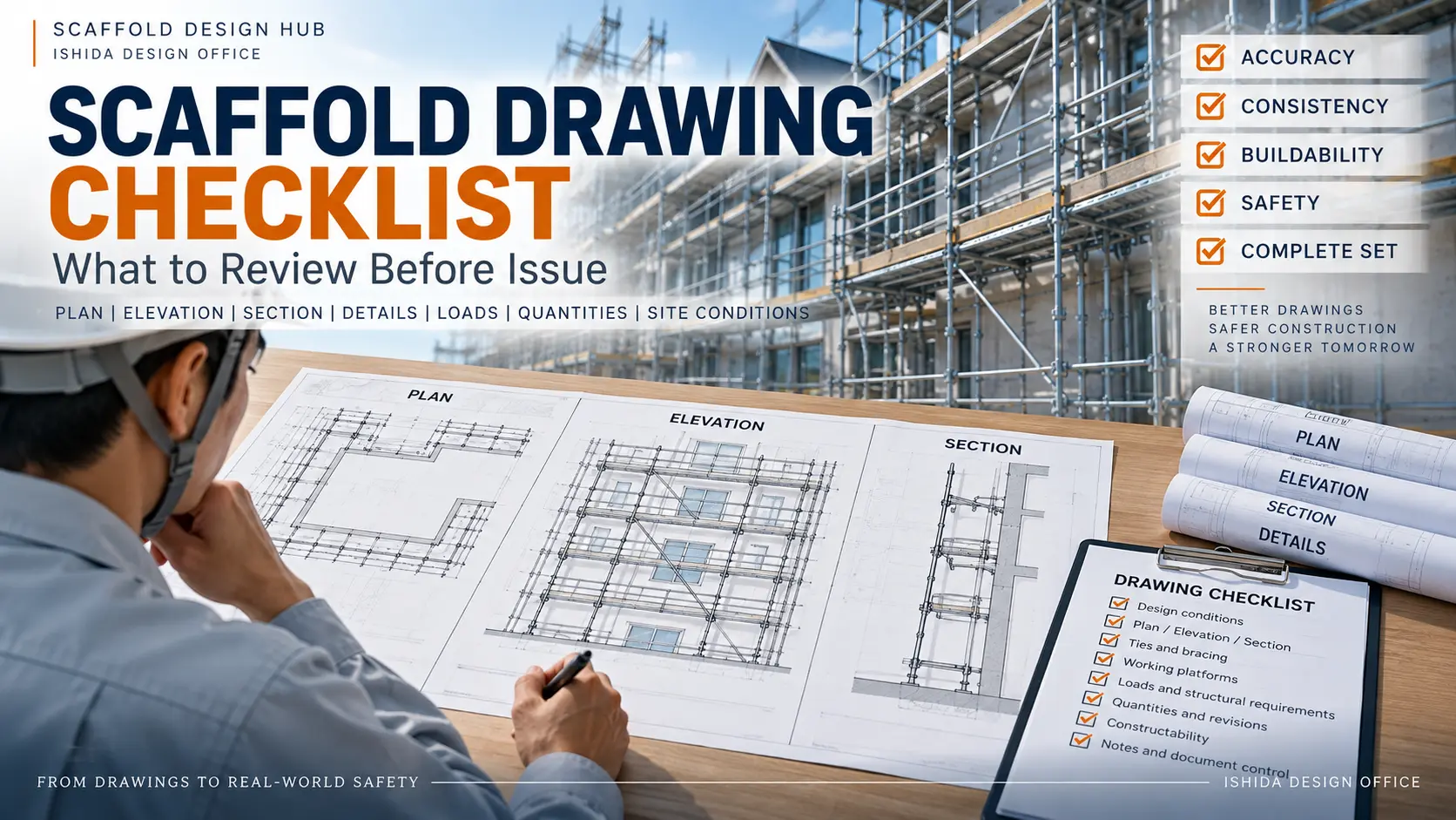
Practical Scaffold Drawing Review Checklist
A checklist does not replace experience.
Its purpose is to make sure experienced people do not lose time to simple omissions.
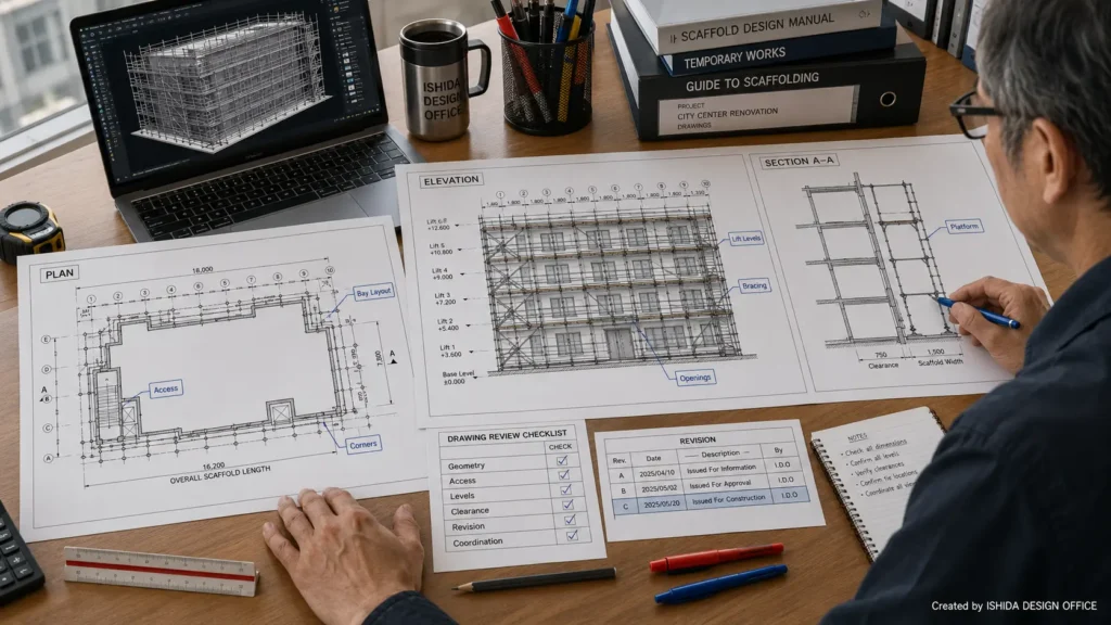
Drawing Control
- Correct project?
- Correct drawing number?
- Current revision?
- Appropriate drawing status?
- Relevant notes checked?
- Scale understood where applicable?
Plan
- Building footprint understood?
- Scaffold footprint clear?
- Bay arrangement coordinated?
- Corners resolved?
- Returns resolved?
- Entrances identified?
- Access identified?
- Loading areas considered?
- Major obstructions shown?
- Section locations clear?
Elevation
- Overall height understood?
- Lift arrangement coordinated?
- Working levels clear?
- Bracing coordinated?
- Ties coordinated?
- Building openings considered?
- Access arrangement clear?
- Roof and height changes considered?
Section
- Scaffold width understood?
- Façade clearance checked?
- Platform relationship clear?
- Balconies considered?
- Canopies considered?
- Roof projections considered?
- Base condition understood?
- Special brackets or details identified?
Final Cross-Check
- Bay counts agree between views?
- Dimensions agree?
- Levels agree?
- Section locations agree with the plan?
- Tie locations are coordinated?
- Bracing does not create obvious access conflicts?
- Details agree with the GA?
- Revisions agree across the drawing set?
If one answer is No, understand why before treating the drawing as coordinated.
DRAWING CHECK: Do not let the site become the place where the drawing is finally coordinated.
How My Japanese Scaffold Drawing Samples Use These Views
On the Japanese ISHIDA DESIGN OFFICE website, I have published examples of scaffold drawings from my own drawing work.
These include:
- external scaffold plans
- external scaffold elevations
- scaffold sections
- enlarged section details
The notation, scaffold systems and construction practices may differ from those used on projects in the US, UK or Australia.
But the basic drawing logic is the same.
The building is three-dimensional.
The scaffold is three-dimensional.
The drawing sheet is two-dimensional.
Plan, elevation, section and detail are how we bridge that gap.
After decades of preparing scaffold drawings, I still consider that one of the most important fundamentals.
The better you can reconstruct the actual scaffold from the drawing, the more useful that drawing becomes.
If you want to see how site conditions are translated into a practical working drawing, continue with How to Create Scaffold CAD Drawings That Actually Work on Site.
FAQ
What is the difference between a scaffold plan and elevation?
A scaffold plan is normally viewed from above and primarily communicates horizontal layout, including bays, footprint, corners and access.
An elevation shows the scaffold vertically from the front or side and is better for understanding height, lifts, platforms, ties and bracing.
They should be read together.
What does a scaffold section drawing show?
A section cuts vertically through the scaffold and building.
It is particularly useful for understanding:
- scaffold width
- façade clearance
- platform position
- balconies
- canopies
- roof edges
- brackets
- base conditions
A section often reveals relationships that are difficult to understand from plan and elevation alone.
Do I need plan, elevation and section drawings for every scaffold?
Not necessarily.
The required documentation depends on:
- scaffold type
- complexity
- jurisdiction
- manufacturer guidance
- recognised standard configurations
- project requirements
- contractual requirements
- site conditions
A simple scaffold erected within an accepted standard configuration may require different documentation from a large bespoke temporary works structure.
Which scaffold drawing should I check first?
I normally begin with the drawing control information and overall arrangement.
Then I use this sequence:
Plan → Elevation → Section → Details → Cross-check
The exact order is less important than making sure the views tell the same story.
Does OSHA require plan, elevation and section drawings?
OSHA Subpart L establishes scaffold requirements and responsibilities relating to scaffold construction, capacity, access, use, training and other issues.
OSHA Appendix E also provides non-mandatory scaffold drawings and illustrations.
However, this should not be interpreted as a universal requirement that every scaffold must have a drawing package containing a plan, elevation and section.
Project-specific documentation depends on the scaffold and applicable requirements.
Can a scaffold be erected directly from any drawing?
No.
Before treating a drawing as construction information, check its purpose and status.
Depending on the project, review:
- drawing status
- revision
- design requirements
- calculations where required
- method statement or work plan
- manufacturer instructions
- local regulations
Never assume that a preliminary, tender or approval drawing is automatically suitable for erection.
Related Topics
Understanding plan, elevation and section is only one part of reading a complete scaffold drawing.
If your next question is how to review the entire drawing package, continue with:
Once the views make sense, the next question is often what dimensions you should check:
Scaffold Dimensions Explained: Bay Length, Lift Height, Width & Standards
When you see tie symbols in the elevation and want to understand their function and arrangement:
Scaffold Ties Explained: Types, Spacing & Layout
And when diagonal members appear in the elevation:
Scaffold Bracing Explained: Types, Layout & Design Principles
These topics belong together.
Plan, elevation and section tell you where to look.
Dimensions, ties, bracing and details tell you what to evaluate there.
Key Takeaways
If you remember only five things from this guide, remember these:
- Plan shows where the scaffold goes.
- Elevation shows how the scaffold rises.
- Section shows how the scaffold fits against the building.
- The three views should be cross-checked, not read independently.
- A good drawing removes uncertainty before uncertainty reaches the site.
There is no need to make the basic method complicated.
Start with the building.
Find the scaffold.
Follow the same location through the plan, elevation and section.
Then check the details.
One scaffold. Three views. One coordinated design.
Conclusion
After more than 30 years working with scaffold and temporary works drawings, I still believe that some of the most valuable checks are surprisingly simple.
A small difference between a plan and an elevation may look insignificant on a monitor.
On site, that same difference can mean additional materials, lost time, difficult access, redesign or a problem that should have been resolved earlier.
That is why I keep returning to the same approach:
Look carefully. Cross-check the views. Understand the real building.
I hope this article helps make your next drawing review easier, your scaffold planning safer and your site coordination smoother.
If you found it useful, I hope you will visit ISHIDA DESIGN OFFICE again.
There is always another drawing to understand, another detail to improve and another small problem we can catch before it becomes a large one.
References
Occupational Safety and Health Administration — OSHA
29 CFR Part 1926 Subpart L — Scaffolds
Federal US construction scaffold requirements, including general requirements, specific scaffold types and training provisions.
Appendix E to Subpart L — Drawings and Illustrations
OSHA identifies Appendix E as non-mandatory visual guidance. It contains scaffold and component drawings together with illustrations of bracing and tie-spacing arrangements.
Health and Safety Executive — HSE, United Kingdom
HSE explains the distinction between recognised standard configurations and scaffolds requiring design calculations, and discusses information needed during scaffold planning.
National Access & Scaffolding Confederation — NASC
TG20 — Tube and Fitting Scaffolding
NASC provides recognised configuration guidance for tube-and-fitting and system scaffolding respectively.
Safe Work Australia
Scaffolds and Scaffolding Work General Guide
Guidance covering scaffold design, planning, erection, use, dismantling and risk management.
ISHIDA DESIGN OFFICE — First-Hand Drawing Examples
Published examples include external scaffold plans, elevations, sections and section details.
Additional practical examples of scaffold plan, elevation, section and detail drawings.
Last Verified: August 2026
Official references and guidance used in this article were checked at the time of writing.
Regulations, standards, manufacturer requirements and industry guidance can change.
Requirements vary by country, jurisdiction and project. Always confirm current requirements through the relevant official authority, project documentation and scaffold manufacturer before applying this information to a specific scaffold.
About the Author
ISHIDA DESIGN OFFICE brings more than 30 years of practical experience in Japan, specializing in scaffolding design, temporary works planning, CAD drafting, quantity estimation, and construction support.
Drawing on experience from residential, commercial, and industrial projects, he shares practical insights that emphasize not only sound engineering design but also buildability, safety, and real-world jobsite application.
At Scaffold Design Hub, he combines practical experience from Japan with official guidance and technical resources from government agencies, manufacturers, and industry organizations around the world to provide reliable, practical information for construction professionals.
To learn more, visit the About page. For questions or project inquiries, please use the Contact page.