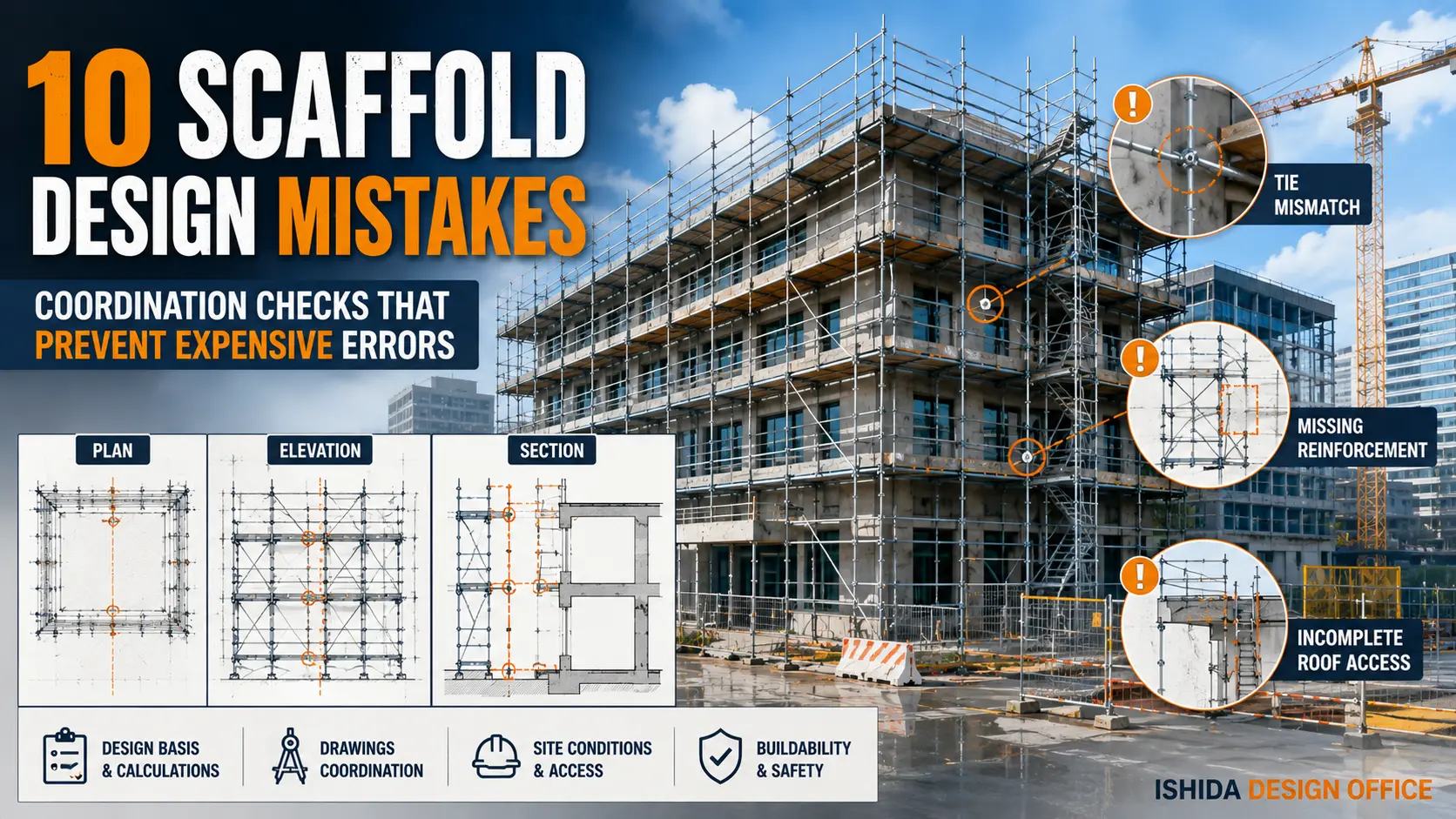
A scaffold drawing can look complete and still contain serious design coordination problems.
The problem is not always an obviously missing component. A tie may appear in both the plan and elevation but at different locations. A structural calculation may identify a required stability provision that never appears on the final drawing. An access route may work on plan but fail when the roof level or building section is considered.
For this reason, reviewing a scaffold design means more than checking whether the expected components appear somewhere on the drawing.
The design basis, calculations, plan, elevation, section, site conditions, access requirements and applicable rules must describe a compatible scaffold.
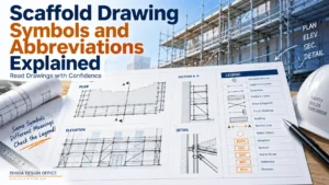
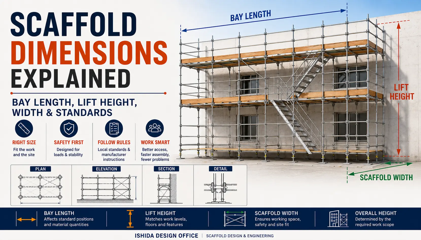
If you are still building confidence in interpreting the different views and information contained in scaffold drawings, see How to Read Scaffold Drawings: Plan, Elevation, Section & Details.
This guide examines 10 common scaffold design and drawing mistakes, focusing particularly on the interface between:
Design Basis → Calculation → Drawing → Site Conditions → Buildability
Important: Scaffold requirements vary by jurisdiction, scaffold system, manufacturer, project and site condition. This article provides general technical guidance and does not replace project-specific engineering, applicable legislation, project specifications, manufacturer instructions or review by appropriately competent professionals.
Why Scaffold Design Mistakes Are Often Coordination Problems
Some scaffold problems are obvious when a drawing is opened. Others appear only when separate pieces of design information are compared.
A plan may look reasonable on its own. The elevation may also appear correct. The structural calculation may be internally consistent.
That does not necessarily mean all three describe the same scaffold.
Under OSHA requirements in the United States, scaffolds must be designed by a qualified person and constructed and loaded in accordance with that design. OSHA also contains specific requirements for the capacity and stability of supported scaffolds.
HSE guidance in Great Britain similarly requires strength and stability calculations unless the scaffold is covered by an existing calculation or recognised standard configuration. It also identifies critical dimensions, working loads, access, restrictions on tie locations, support conditions and building information as relevant inputs to scaffold planning and design.
A useful scaffold drawing review therefore asks two different questions:
Is the required information shown?
Does that information agree with the rest of the design?
The distinction is fundamental to the mistakes that follow.
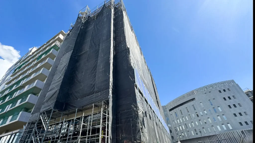
1. Tie Locations Do Not Match Between Plan and Elevation
Scaffold ties create a physical relationship between the scaffold and the supporting structure. That relationship must remain consistent when represented in different drawing views.
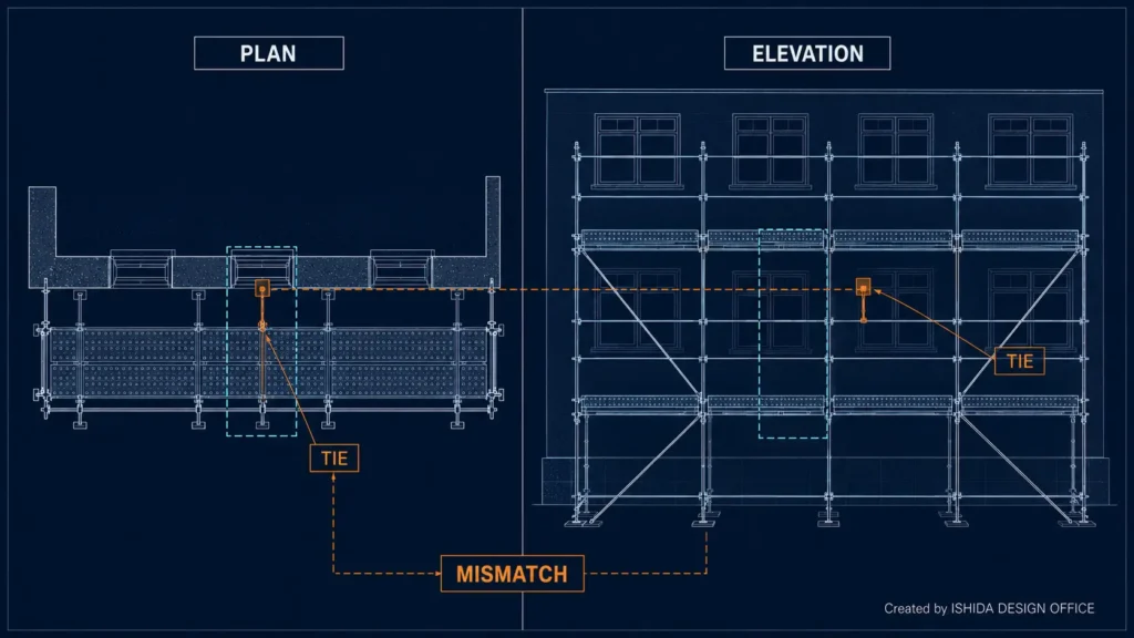
One coordination error occurs when a tie is shown at one scaffold bay in plan but appears at another position in elevation.
Both drawings may look individually plausible, yet together they describe different arrangements.
Why It Matters
The person using the drawing should not have to decide which tie position was intended.
Tie arrangements can form part of the scaffold’s stability system. They must also correspond to locations where an appropriate connection can actually be made to the structure.
OSHA contains specific requirements concerning guys, ties and braces for supported scaffolds in defined circumstances. Those requirements are specific to the United States and should not be treated as universal tie-spacing rules.
Other jurisdictions, scaffold systems and manufacturers may specify different requirements.
For a more detailed explanation of tie types, positioning and the factors that influence tie layouts, see Scaffold Ties Explained: Types, Spacing & Layout.
Better Approach
Before issue, compare tie locations across every relevant drawing view.
- the same scaffold bay is being referenced;
- horizontal and vertical positions remain consistent;
- changes made in one drawing are reflected in other affected views; and
- the final arrangement remains compatible with the applicable design basis.
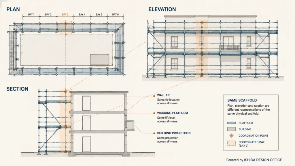
The plan and elevation should be reviewed as two representations of the same scaffold, not as independent drawings.
2. The Drawing Does Not Match the Structural Calculation
A structural calculation and a scaffold drawing perform different functions, but the design conditions they describe must remain compatible.
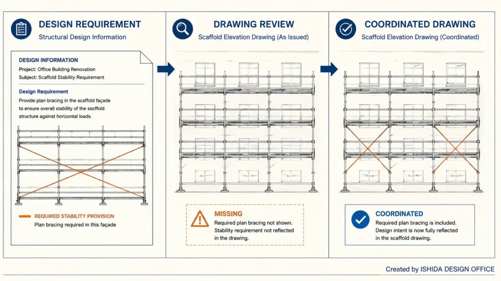
A calculation may identify a loading condition, stability requirement or additional structural provision. If that requirement is not reflected where necessary in the issued drawing, the drawing may no longer represent the design on which it is based.
Why This Gap Matters
A correct calculation does not automatically produce a correct drawing.
The drawing communicates information that will be interpreted by people involved in planning, erection, use or review. If critical design requirements remain only in the calculation package, an information gap can develop between engineering and construction documentation.
Under OSHA 1926.451(a)(6), scaffolds in the United States must be designed by a qualified person and constructed and loaded in accordance with that design.
HSE guidance in Great Britain requires bespoke calculation for scaffolds outside recognised standard configurations and explains that relevant design information may include maximum bay lengths, lift heights, loads, tie spacing and additional designed elements.
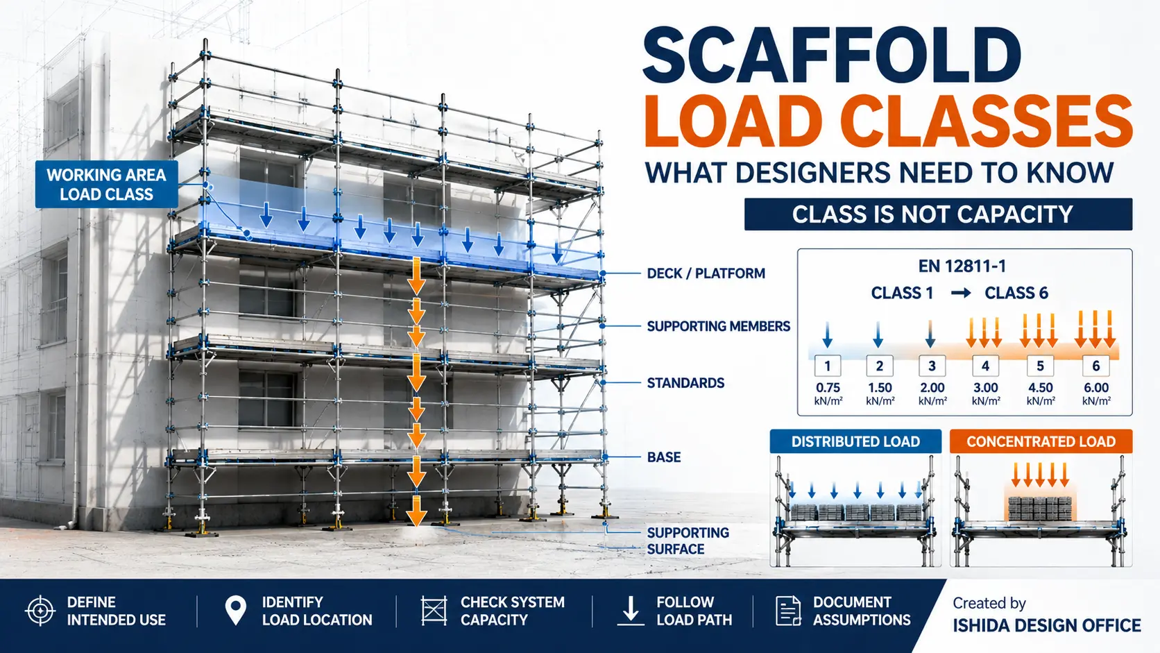
Loading terminology can also be misunderstood when information passes from calculation to drawing. For a focused explanation, see Scaffold Load Classes Explained: What Designers Need to Know.
Better Approach
Before a drawing is issued, compare the final drawing package with the design information that affects what must actually be communicated.
- loading assumptions;
- stability provisions;
- additional structural elements;
- scaffold configuration;
- critical dimensions; and
- project-specific restrictions.
The internal calculation process does not need to be reproduced on the drawing.
What matters is that the scaffold shown remains consistent with the design that supports it.
From my design work: I have seen a case where reinforcement required by the structural calculation was missing from the corresponding scaffold drawing. This is why I compare the design requirements with the information actually shown for construction. The reinforcement type and arrangement must be determined for each project; this example is not a standard detail.
3. Ties Are Shown Where They Cannot Actually Be Installed
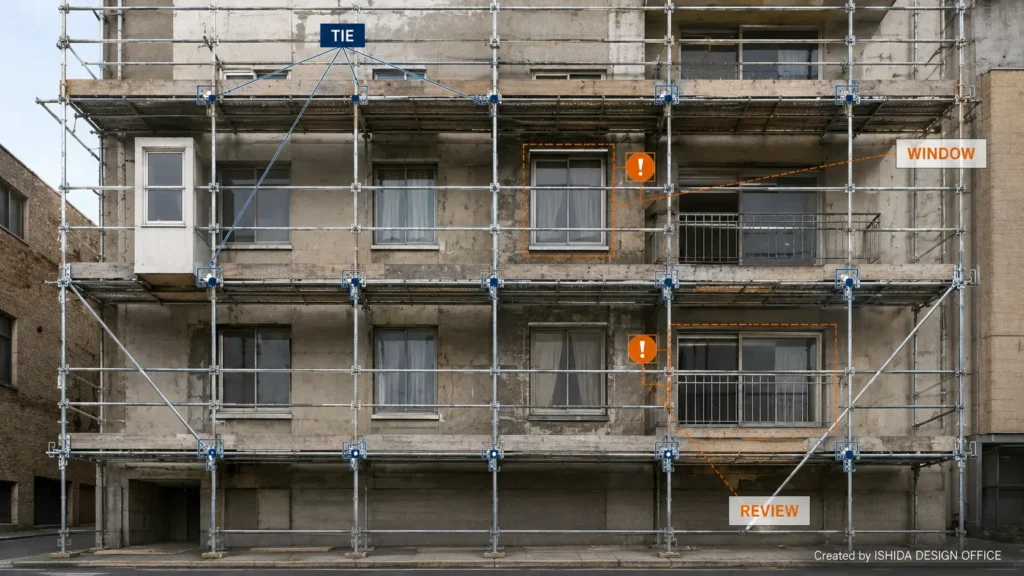
A regular tie pattern can look convincing on an elevation and still be impractical when compared with the building.
Windows, balconies, façade recesses, projecting elements, equipment, cladding systems or other building conditions may prevent a proposed connection from being installed where the drawing shows it.
This is why tie planning cannot be reduced to drawing a repeating grid.
Why It Matters
A graphical tie symbol is not the same thing as a workable physical connection.
HSE guidance identifies restrictions on tie locations as information that may need to be considered during scaffold planning. It also states that proprietary system scaffolds must be erected and tied according to manufacturers’ instructions.
WorkSafe New Zealand guidance further notes within its own jurisdiction that ties must not block access along working platforms and access ways and explains that tie spacing is often determined by design.
The exact technical requirements vary, but the broader design principle remains useful:
Tie positions should be coordinated with the actual building interface, not only with the scaffold grid.
Better Approach
Review proposed tie locations against the available building information.
- windows and other openings;
- balconies;
- façade recesses and projections;
- roof interfaces;
- equipment and services;
- changes in external wall geometry; and
- areas where the supporting structure may differ from what is assumed.
If the intended tie position cannot be used, the solution should be returned for appropriate review rather than being moved arbitrarily during erection.
Related first-hand lesson: I have encountered a situation in which a planned scaffold tie position could not be used and the arrangement required a change in tie position and additional reinforcement. The important point for this review is the need to identify the conflict and return the revised arrangement for appropriate design checks—not to assume that a tie can be moved without consequences. See also Scaffold Design Lessons for the wider practical lessons.
4. Applicable Safety Requirements Are Not Properly Considered
Scaffolding requirements are not identical around the world.
A numerical requirement, terminology or standard configuration used in one jurisdiction should not automatically be transferred to another project.
Requirements can differ according to:
- jurisdiction;
- scaffold type;
- scaffold system;
- height and geometry;
- intended use;
- loading;
- access method;
- manufacturer instructions; and
- project specifications.
Why It Matters
There is no single international set of scaffold dimensions, tie spacings, load limits or other numerical rules that can simply be applied to every project.
OSHA requirements apply within the relevant United States regulatory context. HSE guidance operates within the Great Britain framework. Safe Work Australia provides national policy and guidance while Australian states and territories regulate and enforce WHS laws. New Zealand has its own regulatory framework and WorkSafe guidance.
Even terms such as qualified person and competent person can have jurisdiction-specific legal meanings.
Better Approach
Before applying a numerical rule or treating a configuration as mandatory, establish the relevant design and regulatory context.
- legislation and regulations;
- government or regulator guidance;
- project specifications;
- recognised standards;
- manufacturer documentation; and
- project-specific engineering requirements.
A rule from one jurisdiction should not be presented as a universal scaffold requirement.
5. Roof Access Is Missing or Incomplete
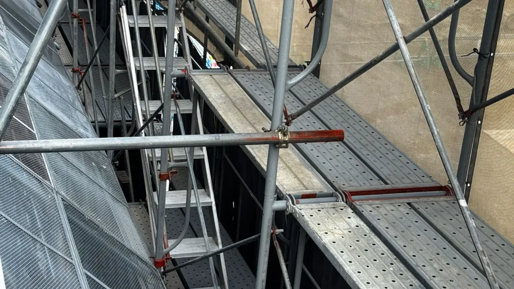
A scaffold can provide effective access to the façade while still failing to show how workers are expected to reach a roof or another required upper work area.
The stair or ladder route may simply terminate at the highest scaffold platform even though the intended destination lies beyond it.
Why It Matters
Access should be considered as part of scaffold planning rather than automatically being left for the site team to resolve after the scaffold configuration has been established.
For scaffolds covered by OSHA in the United States, 1926.451 contains specific access requirements. Where a scaffold platform is more than 2 ft (0.6 m) above or below a point of access, an approved means of access is required. OSHA also prohibits the use of cross braces as a means of access or egress on tubular welded frame scaffolds.
HSE guidance in Great Britain identifies the type of access onto the scaffold as information to establish during planning and recommends safe access to working platforms.
These are jurisdiction-specific requirements, but they demonstrate why access must be deliberately considered in the design information.
Better Approach
Identify the worker’s required destination, not merely the uppermost scaffold lift.
Where roof access is required, review the transition between the scaffold and the roof or other destination.
- building geometry;
- working-platform levels;
- guardrails and edge protection;
- stair or ladder locations;
- roof level and parapets;
- openings; and
- applicable fall-protection requirements.
The purpose of the drawing is not necessarily to prescribe a universal access detail, but it should avoid leaving a critical access relationship unresolved.

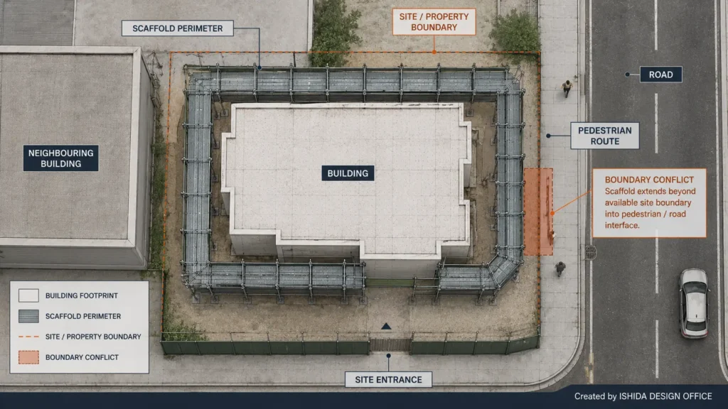
6. Site Boundaries Are Ignored
A scaffold does not exist in empty drawing space.
Property boundaries, site limits, adjacent buildings, roads, pavements, pedestrian routes, equipment and neighbouring land can restrict where a scaffold can actually be placed.
A scaffold plan may therefore be geometrically correct around the building while remaining unsuitable for the available site.
Why It Matters
Designers naturally examine the relationship between the building and the inner face of the scaffold.
The outer face matters too.
HSE guidance on protecting the public addresses construction-site boundaries and the need to prevent hazards such as falling objects from extending beyond the site boundary. Its wider construction guidance also emphasises interaction with pedestrians and vehicles around construction sites.
The exact legal and permission requirements will depend on the project and jurisdiction, but the spatial problem exists wherever the available working area is restricted.
Check the Space Beyond the Scaffold
Where relevant to the scaffold arrangement, show and review the available site limits.
Building → Scaffold → Available Boundary → Surrounding Environment
- adjacent structures;
- roads and pavements;
- pedestrian routes;
- vehicle movement;
- site entrances;
- neighbouring land; and
- limited installation space.
If the boundary or available working area is uncertain, obtain the necessary project information rather than assuming that additional space is available.
What site experience has taught me: I have reviewed scaffold arrangements that looked workable on paper but needed reconsideration once the available space around the building was checked. Roads, neighbouring properties and site boundaries are not secondary details: they can change the arrangement itself. I therefore check the space outside the scaffold perimeter before treating a layout as final.
7. Required Reinforcement or Stability Provisions Are Missing from the Drawing
Mistake 2 concerns the overall consistency between the calculations and the drawing package. This mistake is narrower: even when the general arrangement is coordinated, a specific required brace, tie or reinforcement detail may be missing from the information used for erection.
The engineering assessment may be correct while the issued construction information remains incomplete.
Why It Matters
A scaffold built or reviewed from a drawing needs to correspond to its design basis.
If a design-critical provision exists only in the calculation and is absent from the documentation that communicates what must be installed, the connection between analysis and execution may be lost.
Current HSE guidance states that scaffolds should be braced and tied into a permanent structure or otherwise stabilised and that extra support should be provided where necessary. It also explains that scaffolds outside recognised standard configurations require appropriate design calculations and that relevant design information should be provided before installation.
The type, location and extent of any additional provision are project-specific matters that depend on the structural design, scaffold system, loading and site conditions.
Check What the Site Team Will Actually See
Check the actual installation information: where is the required provision shown, how is it identified, and which drawing or detail tells the site team what must be installed?
Confirm that design-critical elements that need to be installed are communicated in the appropriate project documents.
This does not mean publishing internal calculation procedures, reinforcement algorithms or proprietary design methods.
What has been designed must not disappear when the design becomes a drawing.
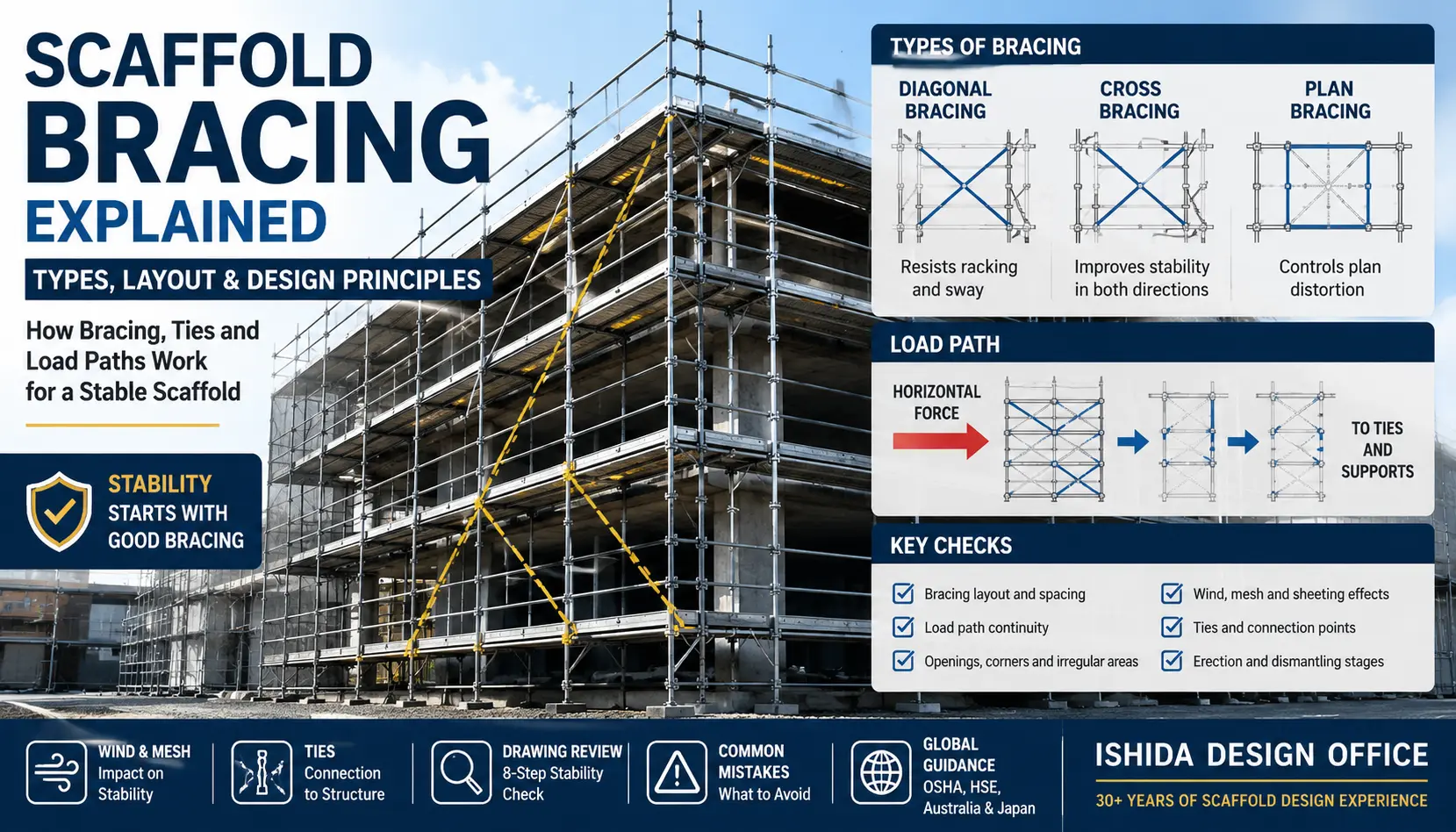
8. Bracing Conflicts with Openings, Access or Other Components
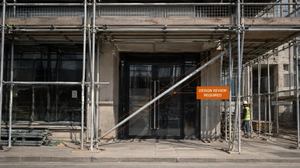
Bracing contributes to scaffold stability, but it also occupies physical space within the scaffold and around the building.
A brace drawn across an entrance, stair route, loading area or other required feature can create a practical conflict.
Why It Matters
A diagonal line may look perfectly acceptable on an elevation until the drawing is compared with the actual building openings or access arrangement.
The opposite response can be equally problematic: removing or relocating a brace simply because it is inconvenient.
Under OSHA requirements in the United States, supported scaffold poles, legs, posts, frames and uprights must be plumb and braced to prevent swaying and displacement, and ties, guys, braces or outriggers are required in specified stability conditions.
HSE guidance likewise emphasises adequate bracing, tying and stabilisation of scaffolds within its applicable context.
For a deeper explanation of how bracing relates to scaffold stability, openings and layout, see Scaffold Bracing Explained: Types, Layout & Design Principles.
Better Approach
Coordinate bracing with the other functional requirements of the scaffold and building.
- entrances;
- staircase and ladder locations;
- loading areas;
- building openings;
- projecting architectural elements;
- working platforms;
- material movement routes; and
- other scaffold components.
Where a conflict is found, return the condition for appropriate design review.
Do not assume that relocating or removing a stability component has no structural consequence.
9. Plan, Elevation and Section Are Not Properly Cross-Checked
A scaffold is three-dimensional.
Most scaffold drawings divide that three-dimensional arrangement into two-dimensional views.
Unlike Mistake 1, which focuses on tie positions, this review covers the full relationship between plan, elevation and section—including levels, clearances, access and changes across drawing revisions.
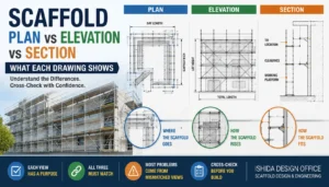
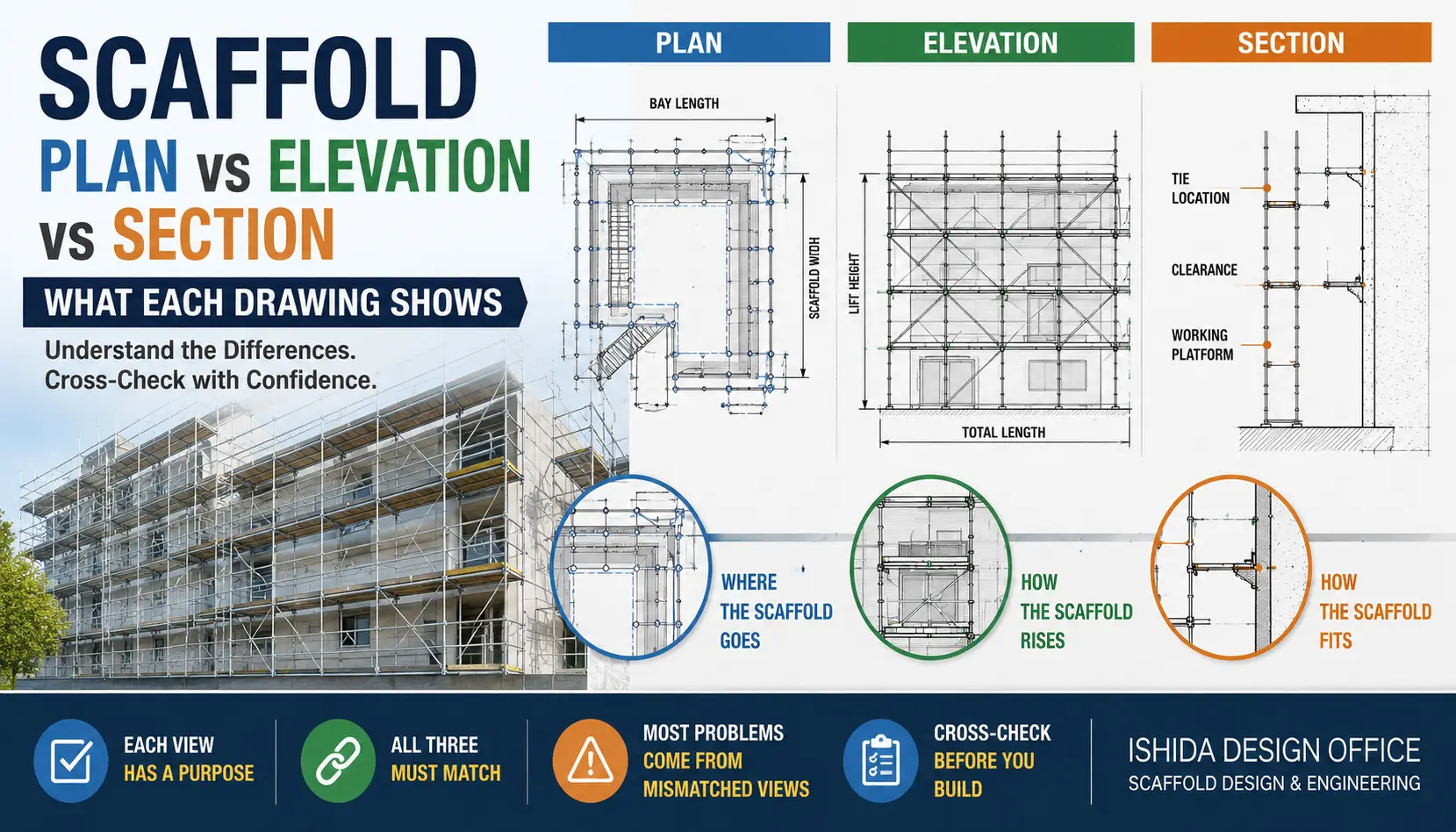
The role of each view is examined in more detail in Scaffold Plan vs Elevation vs Section: What Each Drawing Shows.
Why It Matters
Each view reveals different information.
Plan primarily shows horizontal geometry, scaffold position, bay arrangement and relationships around the building.
Elevation communicates vertical arrangement, lift levels, façade relationships and components distributed along the height and length.
Section can reveal scaffold width, building clearance, projections, work-platform relationships and vertical conditions that may not be obvious in the other views.
Reviewing each view independently can therefore hide conflicts.
A working platform that appears correct on an elevation might conflict with a balcony visible in section. A tie position that appears reasonable in plan may correspond to an unsuitable façade condition when the elevation is checked.
Cross-Check Every Affected View
Treat every drawing view as a representation of one physical scaffold. For each revision, check whether it affects:
My drawing-review practice: When one drawing view changes, I check the corresponding locations and dimensions in the other views. This is especially important when an adjustment affects a bay, working level, tie, brace or access route. A revision should not leave the drawing set describing two different arrangements.
- another drawing view;
- scaffold dimensions;
- ties;
- bracing;
- access;
- working platforms;
- building clearances; or
- other project-specific design information.
The review question should not be:
“Is each drawing individually correct?”
It should be:
“Do all the drawings describe the same buildable arrangement?”
10. The Design Is Based on Assumptions Instead of Confirmed Site Information
Incomplete information can create pressure to continue drawing.
Missing dimensions, uncertain openings, unclear boundaries, unknown roof geometry or incomplete building information may gradually be replaced with assumptions simply so that the drawing can be completed.
The finished drawing can then look more certain than the information on which it was based.
Why It Matters
HSE guidance identifies a broad range of information that may be required at the beginning of scaffold planning, including site location, intended use, critical dimensions, working loads, scaffold access, restrictions on tie locations, supporting conditions and information or drawings relating to the building.
HSE’s temporary-works guidance also notes that assumptions behind a standard solution need to remain valid for the particular site conditions in which it is being used.
Uncertainty should be identified rather than hidden by a finished-looking drawing.
Better Approach
If information that materially affects the scaffold is missing, obtain or clarify it before treating the relevant part of the design as final.
- architectural drawings;
- structural drawings;
- critical dimensions;
- photographs;
- façade information;
- site or property boundaries;
- roof geometry;
- access requirements;
- loading requirements;
- scaffold-system information; and
- clarification from the relevant project party.
A drawing from a previous project should not be assumed applicable merely because the buildings appear similar.
Each scaffold must be considered against the actual conditions that affect that project.
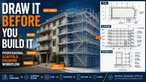
For the wider sequence from project information and design decisions through to a coordinated drawing package, see How to Create a Scaffold Drawing: Step-by-Step Design Workflow.
A Practical Scaffold Drawing Review Checklist
The following checklist is deliberately high-level.
It is intended to help identify coordination issues before a scaffold drawing is issued. It does not replace structural calculations, statutory inspections, manufacturer requirements or project-specific design procedures.
Drawing Coordination
- ☑ Do the plan, elevation and section describe the same scaffold arrangement?
- ☑ Are tie locations consistent between all relevant views?
- ☑ Are major dimensions coordinated across the drawing package?
- ☑ Are scaffold levels and building levels clearly coordinated?
- ☑ Are revisions reflected in every affected drawing or detail?
Calculation and Design Information
- ☑ Does the drawing remain consistent with the relevant design basis?
- ☑ Are design-critical stability provisions communicated where required?
- ☑ Are relevant loading assumptions reflected in the documentation?
- ☑ Have drawing changes been checked against affected design information?
- ☑ Are non-standard conditions clearly identified for appropriate review?
Ties and Bracing
- ☑ Can the proposed ties actually be installed at the locations shown?
- ☑ Have windows, balconies, projections and façade changes been considered?
- ☑ Are tie locations coordinated between plan and elevation?
- ☑ Does bracing conflict with entrances, access routes or loading areas?
- ☑ Have project-specific restrictions affecting ties or bracing been identified?
Access
- ☑ Is safe access to required working levels considered?
- ☑ Is roof access addressed where the work requires roof-level access?
- ☑ Are stair and ladder locations coordinated with platforms and building geometry?
- ☑ Are access routes affected by ties, braces or other components?
Site Conditions
- ☑ Are relevant site or property boundaries identified?
- ☑ Is sufficient physical space available for the scaffold shown?
- ☑ Have adjacent structures been considered?
- ☑ Have pedestrian and vehicle routes been considered where relevant?
- ☑ Have significant building projections or obstructions been checked?
- ☑ Do available site conditions support the assumptions used in the drawing?
Information and Compliance
- ☑ Is the applicable jurisdiction and design basis identified?
- ☑ Have relevant manufacturer instructions been considered?
- ☑ Are project specifications and engineering requirements reflected where applicable?
- ☑ Have unsupported universal assumptions been avoided?
- ☑ Are unresolved conditions clearly identified?
- ☑ Is additional information required before the drawing can be considered final?
FAQ
What is one of the most common scaffold drawing coordination problems?
One important problem is inconsistency between different drawing views.
Tie locations, dimensions, platforms, access arrangements or other components can appear differently between plan, elevation and section. These drawings should be treated as different representations of the same scaffold rather than as independent documents.
Should a scaffold drawing be checked against the structural calculation?
Where structural calculations form part of the scaffold design, the calculation and drawing should describe compatible design conditions.
Design-critical requirements that need to be installed should not disappear during the transition from engineering analysis to the final drawing package.
Can a wall tie simply be moved if the location shown on the drawing cannot be used?
Not automatically.
Changing a tie location may affect the design assumptions or stability arrangement. The appropriate response depends on the scaffold system, structural design, building, manufacturer requirements, applicable rules and site conditions.
If the intended location cannot be used, the change should be subject to the appropriate project-specific review.
Why are plan, elevation and section all important?
They communicate different aspects of the same scaffold.
Plan is particularly useful for horizontal geometry and positioning. Elevation shows vertical arrangement and façade relationships. Section can reveal scaffold width, building clearance, projecting elements and working-level relationships.
Cross-checking the views can expose conflicts that are difficult to identify from one drawing alone.
Are scaffold design requirements the same in every country?
No.
Legal requirements, official guidance, terminology, standards and accepted configurations vary between jurisdictions.
Requirements may also depend on the scaffold system, manufacturer, intended use, project specifications and site conditions. The rules applicable to the actual project should therefore be identified before numerical requirements or configurations are applied.
Related Scaffold Design Guides
If you want to continue from design review into the individual elements of scaffold drawing preparation, the following guides provide the most relevant next steps.
- How to Read Scaffold Drawings: Plan, Elevation, Section & Details
- Scaffold Plan vs Elevation vs Section: What Each Drawing Shows
- Scaffold Ties Explained: Types, Spacing & Layout
- Scaffold Bracing Explained: Types, Layout & Design Principles
- Scaffold Load Classes Explained: What Designers Need to Know
- How to Create a Scaffold Drawing: Step-by-Step Design Workflow

Final Thoughts
A good scaffold drawing review is not just a visual check for missing lines or dimensions.
It is a coordination check.
When these questions are considered together, a scaffold drawing becomes more than a collection of plans, elevations and sections.
It becomes a coordinated technical description of one scaffold.
A drawing should not merely look complete. Its information should agree.
Official References
The following official sources were used to verify regulatory and guidance statements in this article.
U.S. Occupational Safety and Health Administration (OSHA)
29 CFR 1926.451 — General Requirements for Scaffolds. Used for U.S.-specific requirements concerning scaffold design, capacity, stability, ties, braces and access.
OSHA — 29 CFR 1926.451 General Requirements for Scaffolds
UK Health and Safety Executive (HSE)
Scaffolds — Construction Guidance. Used for Great Britain-specific guidance concerning scaffold planning information, strength and stability calculations, bespoke design, ties, access, loading and information to be communicated by the scaffold designer.
Protecting the Public. Used for construction-site boundary and public-interface considerations.
Temporary Works — Frequently Asked Questions. Used to support the principle that assumptions behind standard solutions must remain valid for the actual site conditions in which they are used.
Safe Work Australia
Guide to Scaffolds and Scaffolding. Used to confirm the Australian national guidance context and the role of state and territory WHS regulators.
Safe Work Australia — Guide to Scaffolds and Scaffolding
WorkSafe New Zealand
Scaffolding in New Zealand. Used for New Zealand-specific guidance concerning scaffold ties, access and stability.
WorkSafe New Zealand — Scaffolding in New Zealand
Last Verified:
September 2026
Regulations, official guidance, standards and manufacturer documentation can change. Always confirm the current requirements applicable to the jurisdiction, scaffold system, project and site conditions.
This article provides general technical information only. Applicable legislation, contract documents, project specifications, manufacturer instructions and project-specific engineering requirements take precedence.
About the Author
ISHIDA DESIGN OFFICE was established in Japan in 1998 and provides scaffolding design, temporary works planning, CAD drafting, quantity estimation, and construction support.
Drawing on experience from residential, commercial, and industrial projects, its founder shares practical insights that emphasize buildability, safety, and real-world jobsite application alongside engineering design.
At Scaffold Design Hub, he combines practical experience from Japan with official guidance and technical resources from government agencies, manufacturers, and industry organizations around the world to provide reliable, practical information for construction professionals.
To learn more, visit the About page. For questions or project inquiries, please use the Contact page.