
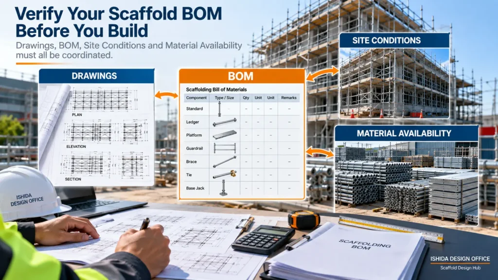
A scaffolding bill of materials (BOM) is more than a total count of standards, ledgers, platforms, guardrails, ties and other components. A useful BOM must identify the correct components, in the correct types and sizes, for the scaffold shown on the current drawings and intended for the actual project conditions.
This is where errors can occur even after the basic quantity calculation appears complete.
In scaffold design work since 1998, I have learned that some of the most important BOM checks are not complicated calculations. They are practical cross-checks: Are the inner and outer guardrails being treated correctly? Can the specified ties actually be installed where they are shown? Have corner components been counted twice? Does the BOM still match the latest drawing and site information? Are the listed component types actually available for the project?
This guide explains how to move from scaffold drawings and calculated quantities to a material list that can be checked systematically before it is used for planning, allocation or procurement.
What Is a Scaffolding Bill of Materials?
A scaffolding bill of materials is an organized list of the components required for a defined scaffold arrangement.
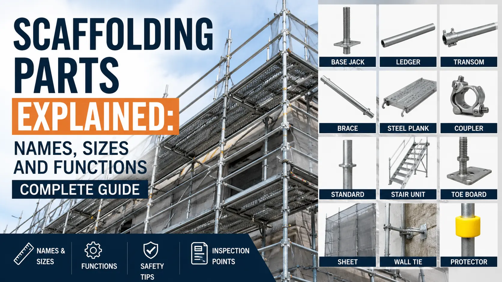
Depending on the scaffold system and project, the list may include:
- standards or vertical members,
- ledgers or horizontal members,
- transoms,
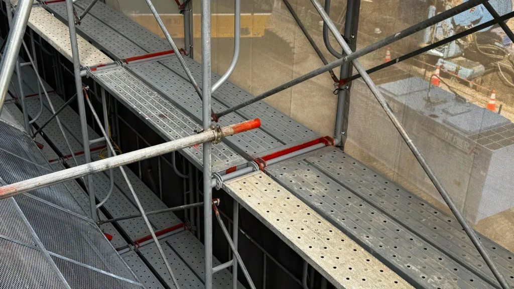
- working platforms or decks,
- guardrails,
- braces,
- ties and anchoring-related components,
- base components,
- brackets,
- access components,
- stairs or ladders,
- toe boards or edge-protection components,
- and other system-specific or project-specific items.
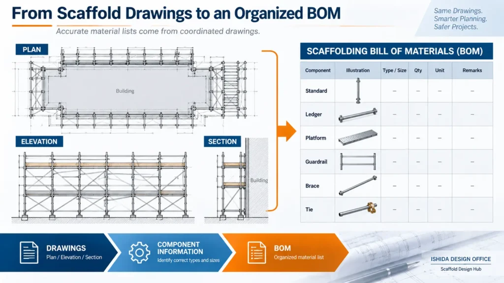
A useful BOM should normally distinguish components by more than name alone. Where relevant, type, size, length, quantity, unit and remarks should also be recorded.
For example, writing only:
Standards — 120 pcs
may not provide enough information if several standard types or lengths are required.
The objective is not simply to produce a large table. It is to create a list that corresponds clearly to the scaffold arrangement being planned.

A Material Takeoff and a BOM Are Not Exactly the Same Thing
Material takeoff and BOM are closely related, but it is useful to distinguish their roles.
A material takeoff is primarily the process of identifying and counting components from drawings and other project information.
A bill of materials organizes those results into a structured material list that can be reviewed and used for subsequent planning.
A simplified workflow is:
Drawings → Material Takeoff → Classification → BOM → Verification
This distinction matters.
You may correctly determine that a scaffold requires a certain number of vertical members, but the BOM can still be wrong if those members are classified under the wrong type or size.
Similarly, the total number of guardrails may look reasonable while the inner and outer sides of the scaffold actually require different arrangements.
An accurate takeoff is therefore essential, but it does not eliminate the need for BOM verification.
What Information Should Be Checked Before Creating a Scaffold BOM?
The quality of a BOM depends heavily on the information used to create it.
Before finalizing the material list, check the available project information, which may include:
- scaffold plan,
- scaffold elevations,
- sections,
- detail drawings,
- scaffold dimensions,
- working levels,
- access arrangements,
- tie layout,
- bracing layout,
- building geometry,
- openings and projections,
- scaffold system or manufacturer information,
- drawing revision status,
- and relevant site information.
Do not rely on one drawing view when another view changes the interpretation.
A plan may show the overall scaffold footprint, but it may not fully communicate vertical changes. An elevation may show lift arrangements and ties, while a section may clarify platform widths, brackets, inner-side conditions or interfaces with the structure.
The BOM should therefore be treated as an output of coordinated information, not as a quantity table created from one drawing in isolation.
What Should a Scaffolding BOM Include?
There is no single universal BOM format suitable for every scaffold system and every project.
However, a practical structure commonly needs fields such as:
| Field | Purpose |
|---|---|
| Item / Component | Identifies the component |
| Type | Distinguishes system-specific variants |
| Size / Length | Prevents different sizes being combined |
| Quantity | Records required count |
| Unit | Clarifies pcs, sets or other units |
| Drawing / Zone | Helps trace the quantity to an area |
| Remarks | Records relevant qualifications or checks |
For more complex scaffolds, separating the list by elevation, zone, level or scaffold area can make checking easier.
The important point is traceability.
If a quantity looks suspicious during the final review, someone should be able to determine where that quantity came from rather than having to recreate the entire takeoff.
How to Create a Scaffolding BOM Step by Step
Step 1: Work From the Current Scaffold Drawings
Start by confirming which drawings and revisions the takeoff is based on.
This sounds basic, but it becomes increasingly important as a project changes. A quantity calculated correctly from an obsolete drawing is still the wrong quantity for the current arrangement.
Plan, elevation and section should be cross-checked where they contain information relevant to the material list.
If a later revision changes scaffold length, height, access, brackets, ties or another material-related feature, the effect on the BOM should be reviewed.
Step 2: Divide the Scaffold Into Logical Areas
For a simple rectangular scaffold, quantities may be relatively straightforward.
Real buildings are often less uniform.
There may be:
- different elevations,
- corners,
- setbacks,
- changes in height,
- projections,
- entrances,
- balconies,
- roofs,
- access towers,
- loading areas,
- or locally modified scaffold arrangements.
Dividing the scaffold into logical areas can make the takeoff easier to review.
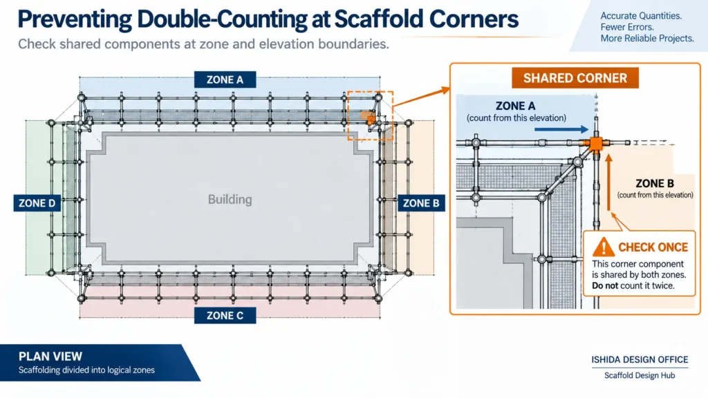
However, this introduces another risk: components at the boundary between two areas can be counted twice.
Zone-based counting therefore needs a boundary check before totals are combined.
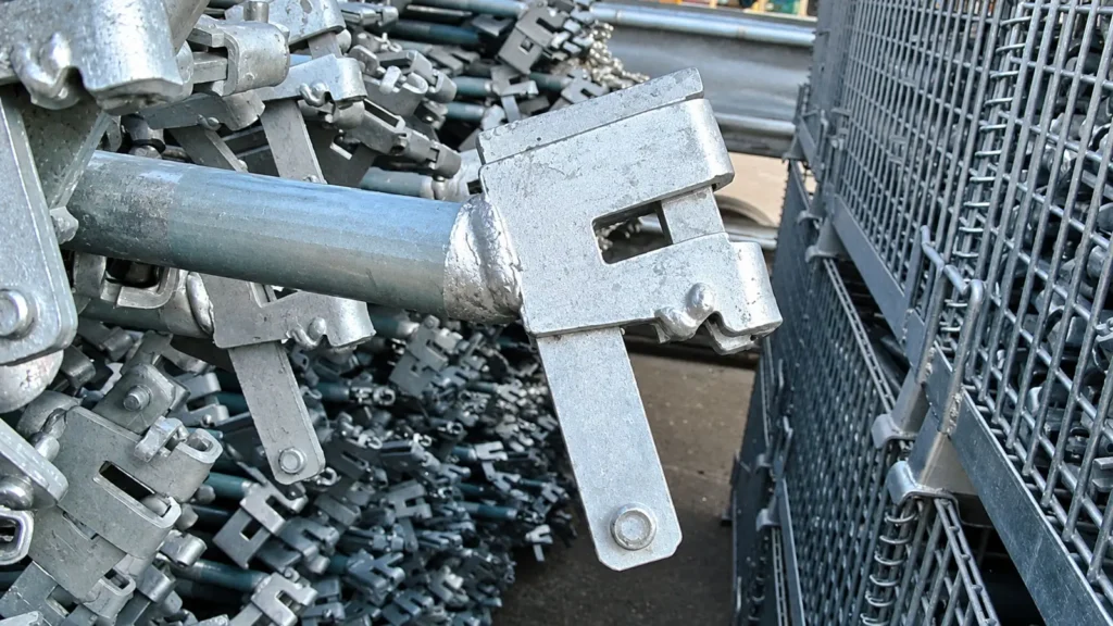
Step 3: Identify Component Types and Sizes
Do not group components simply because they perform a similar function.
A scaffold may contain several lengths or types of standards, ledgers, platforms, brackets or other system components.
The BOM should preserve the distinctions that matter for the scaffold being planned.
This is especially important for standards.
A total standard count can appear correct while the breakdown by type is incorrect. That error may not become obvious until material allocation or erection planning.
Component identification should therefore be checked before the final totals are accepted.
Step 4: Count Repetitive Components Carefully
Repetition is one of the reasons scaffold material estimation can be efficient, but it can also create false confidence.
A long regular elevation may contain many repeated bays and lifts. Once the repeating arrangement is understood, the main components can be counted systematically.
But first identify where the repetition stops.
Exceptions may include:
- ends,
- corners,
- height changes,
- access areas,
- openings,
- brackets,
- special bays,
- top levels,
- or other non-standard arrangements.
Do not apply a standard repeating count through an area where the geometry or scaffold arrangement has changed.
Step 5: Check Guardrails and Working Levels
Guardrail quantities deserve a separate check.
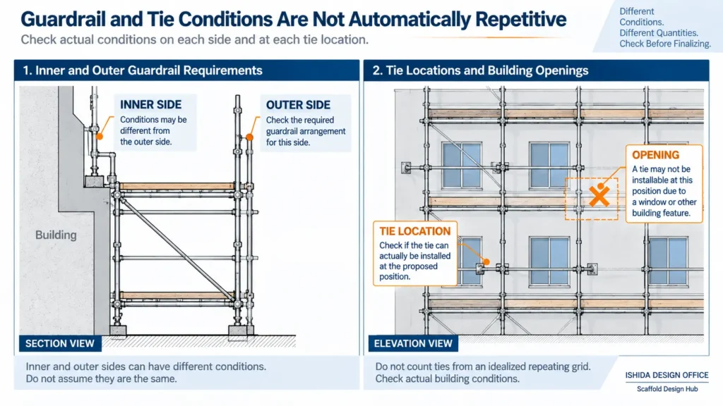
One practical source of error is assuming that the inner and outer sides of the scaffold use the same guardrail arrangement.
That is not always the case.
The building interface, working platform arrangement, project requirements and scaffold configuration may result in different conditions on each side.
Instead of applying one guardrail quantity automatically to both sides, check the relevant drawing and project requirements.
This is a good example of why a BOM cannot be created reliably from scaffold area alone.
Step 6: Check Ties and Bracing From Their Actual Layout
Ties should not simply be converted from scaffold area into a convenient estimated quantity when a project-specific layout is available or required.
The actual arrangement matters.
A particularly important practical issue is installation feasibility.
A tie may appear possible when looking only at a regular scaffold grid, but the corresponding building location may contain an opening or another condition that prevents the assumed connection from being made as intended.
The tie quantity should therefore correspond to a reviewed layout and applicable project requirements, not just a theoretical repeating pattern.
The same general principle applies to bracing: identify the arrangement from the relevant design information rather than treating bracing as an arbitrary percentage of the scaffold.
Where tie or bracing design requires engineering assessment, follow the applicable project requirements, manufacturer information and relevant local rules.
Step 7: Review Corners and Non-Standard Areas
Corners are a common place for quantity errors.
If Elevation A is counted independently and Elevation B is counted independently, the shared corner can accidentally appear in both totals.
The individual calculations may each look reasonable.
The error becomes visible only when the combined BOM is checked as one scaffold.
This is why the final takeoff should include a specific check for:
- shared corner components,
- interfaces between zones,
- scaffold ends,
- transitions,
- brackets,
- access areas,
- and other non-standard geometry.
The purpose is not merely to confirm arithmetic. It is to confirm that the physical scaffold has been counted once.
Step 8: Organize the Quantities Into the BOM
Once the component quantities have been reviewed, organize them into a consistent list.
For example:
| Component | Type / Size | Quantity | Unit | Remarks |
|---|---|---|---|---|
| Standard | Type / length as applicable | — | pcs | Verify by level/zone |
| Ledger | Length as applicable | — | pcs | Separate different lengths |
| Platform | Type / length as applicable | — | pcs | Check working levels |
| Guardrail | Type / length as applicable | — | pcs | Check inner/outer conditions |
| Brace | System-specific | — | pcs | Confirm against layout |
| Tie | System/project-specific | — | pcs | Confirm actual locations |
| Bracket | Type / width as applicable | — | pcs | Check local conditions |
| Access component | As applicable | — | pcs/set | Check access arrangement |
The quantities above are intentionally blank because the correct values depend on the actual scaffold.
A generic example should never be mistaken for a project quantity.
Real Project Example: Scaffold Material Quantity Schedule from Japan
The following material quantity schedule comes from a building renovation project for which I prepared the scaffold design in Japan. It provides a practical example of how the required components can be separated by product code and quantity rather than grouped into a single approximate total.
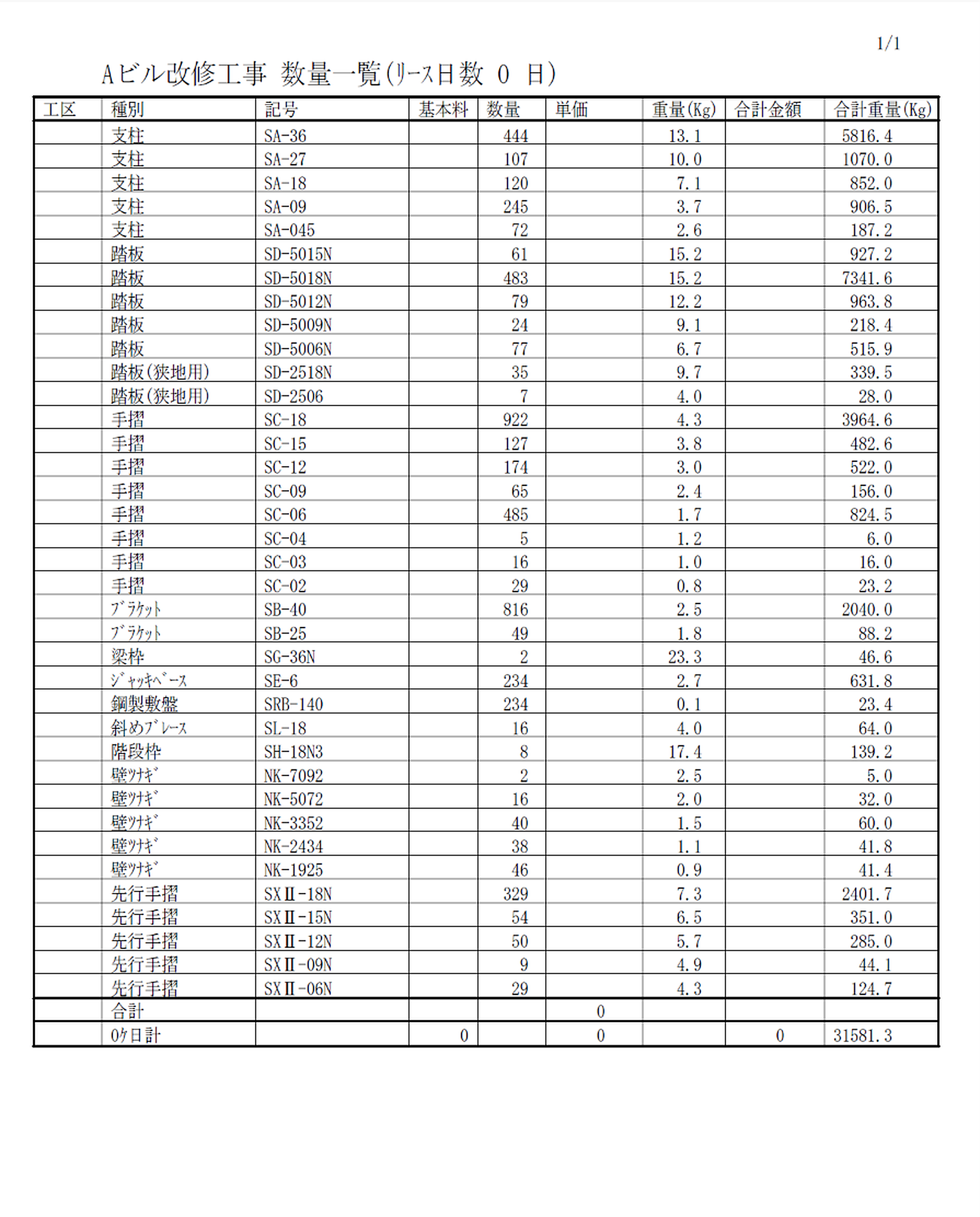
For example, the schedule lists several standard sizes (SA-36, SA-27, SA-18, SA-09 and SA-045) separately. It also distinguishes platform types, guardrails, brackets, base components, braces, stair frames, wall ties and advanced guardrail components. This is why a material list needs to preserve product specifications: an overall count alone cannot show whether the correct components have been allocated.
The original Japanese schedule includes columns for quantities, unit weights and total weights, with a displayed overall weight of 31,581.3 kg. Its lease-period and pricing fields are not populated for a meaningful cost estimate; the example is presented to illustrate component identification and material quantities, not rental pricing. The schedule is a record of one project, not a universal BOM or a substitute for checking the current drawings, approved design and manufacturer specifications.
How I Verify a BOM After 3D CAD Quantity Calculation
In my scaffold design work, I first model the planned scaffold in 3D CAD and use the model to calculate component quantities automatically. I then check the resulting material schedule against the drawings and the requirements of the actual project before issuing it. An automatically generated list is a starting point for my final review, not a finished BOM.
Top-level guardrails are one of my priority checks. I review the guardrail arrangement at the highest working level to confirm that it meets the applicable national safety requirements, the relevant company or scaffold-system rules, and the client’s requirements. I do not assume that the arrangement at the top is identical to the typical levels below.
Buildings with many entrances and openings need particular care. These interruptions can make the scaffold layout less repetitive, increasing the risk of missing components or accepting incorrect quantities. I check these locations individually against the 3D model and drawings rather than relying only on the overall automated total.
My final check is whether the quantities in the schedule actually describe the scaffold I have designed. 3D CAD makes counting more efficient, but I still review the details that can be missed when a material list is accepted without checking.
Step 9: Check Material Availability
This step is easy to overlook because it sits between design information and site logistics.
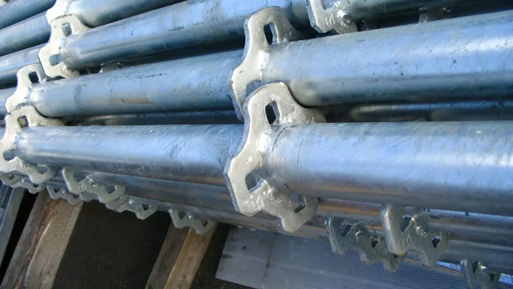
A BOM can be internally consistent and still be difficult to use if it assumes a component type that is not actually available for the project.
In practice, the distinction should be clear between:
what the scaffold arrangement requires
and
what material is currently available or allocated.
Do not silently change the design requirement simply to match stock.
Instead, identify the mismatch and have the appropriate person review how it should be resolved in accordance with the scaffold system, design requirements and project procedures.
This prevents a stock problem from being hidden inside what appears to be a completed BOM.
Step 10: Cross-Check the BOM Against the Latest Drawings
The final check should return to the source information.
Do not finish with the spreadsheet.
Finish with the scaffold.
Review the BOM against:
1. the latest plan, 2. the latest elevations, 3. relevant sections and details, 4. the tie and bracing arrangements where applicable, 5. current site information, 6. and the component types intended for use.
A useful question is:
If this list were handed to another experienced person, could they trace the important quantities back to the scaffold shown on the drawings?
If not, the BOM may need more structure or documentation.
Six Practical BOM Problems I Have Learned to Watch For
The following problems are based on issues I have learned to watch for through long-term scaffold drawing and design work. They are not universal rules for every scaffold system, but they are useful practical review points.
1. Confusing Inner and Outer Guardrail Requirements
Mistake: Applying the same guardrail arrangement automatically to both sides of the scaffold.
Why it matters: The inner side and outer side can have different conditions. Treating them as identical can produce incorrect quantities.
Better approach: Check each side against the relevant scaffold section, elevation and project requirements before combining the quantities.
2. Counting Ties Where They Cannot Actually Be Installed
Mistake: Counting ties from an idealized repeating grid without checking the building interface.
Why it matters: Some assumed positions may conflict with openings or other site conditions, meaning the intended attachment cannot be made there.
Better approach: Review the actual proposed tie locations against the structure and relevant project information. Where necessary, the arrangement should be reviewed by the appropriate responsible person rather than simply moving a tie for quantity convenience.
3. Drawings and Site Conditions No Longer Match
Mistake: Continuing to use a BOM after the drawing or site condition has changed.
Why it matters: Even a correctly prepared original BOM can become obsolete.
Better approach: Maintain a clear relationship between drawing revision, site information and BOM revision. When a material-related change occurs, identify which parts of the BOM may be affected.
4. Double-Counting Components at Corners
Mistake: Counting two elevations independently and including a shared corner component in both.
Why it matters: The error may survive individual elevation checks because each local count appears logical.
Better approach: After zone or elevation totals are combined, perform a separate interface and corner review.
5. Counting the Wrong Type of Standard
Mistake: Getting the total number of standards approximately right but assigning them to the wrong component type or length.
Why it matters: A BOM is not accurate simply because its grand total looks reasonable.
Better approach: Keep relevant component types and sizes separate throughout the takeoff and final list.
6. Listing Components That Are Not Actually Available
Mistake: Preparing the material list on the assumption that a required component type is available when it is not available for the actual project allocation.
Why it matters: The BOM may be correct as a theoretical requirement but unusable as an immediate material-allocation list.
Better approach: Compare the required BOM with actual availability as a separate control step. If there is a mismatch, identify it explicitly rather than changing the design requirement informally.
Example Scaffolding BOM Structure
A simple professional BOM might use columns such as:
| Item No. | Component | Type / Size | Zone | Quantity | Unit | Drawing Revision | Remarks |
|---|---|---|---|---|---|---|---|
| 01 | Standard | As specified | A | — | pcs | Rev. — | — |
| 02 | Ledger | As specified | A | — | pcs | Rev. — | — |
| 03 | Platform | As specified | A | — | pcs | Rev. — | Working level |
| 04 | Guardrail | As specified | A | — | pcs | Rev. — | Outer side |
| 05 | Guardrail | As specified | A | — | pcs | Rev. — | Inner side |
| 06 | Brace | As specified | A | — | pcs | Rev. — | Check layout |
| 07 | Tie | As specified | A | — | pcs | Rev. — | Check locations |
The exact structure should suit the project and scaffold system.
The important principle is that the table should help verification, not merely store numbers.
A Practical Scaffold BOM Final Review Checklist
Before releasing or using a scaffolding BOM, consider the following checks.
Drawing Control
- Is the BOM based on the current drawing revision?
- Have plan, elevation and relevant sections been reviewed?
- Have drawing changes that affect materials been reflected in the BOM?
- Are special details or non-standard areas included?
Component Identification
- Are component types identified correctly?
- Are different lengths and sizes kept separate?
- Have standards been classified correctly?
- Are brackets and access components included where required?
Guardrails and Platforms
- Have inner and outer guardrail conditions been checked separately?
- Has the top-level guardrail arrangement been checked against applicable rules and client requirements?
- Are working levels identified correctly?
- Have platform-related components been checked against the actual arrangement?
Ties and Bracing
- Does the tie quantity correspond to the reviewed arrangement?
- Have actual attachment locations and building interfaces been considered?
- Has bracing been checked against the relevant drawing or design information?
Geometry
- Have corners been checked for double-counting?
- Have zone boundaries been checked?
- Have height changes and setbacks been considered?
- Have entrances, openings and other exceptions been reviewed?
- Have quantities at buildings with numerous entrances or openings been checked individually?
Material and Site Coordination
- Does the BOM correspond to current site information?
- Are the specified component types actually available for the intended project allocation?
- Are unavailable components clearly identified rather than silently substituted?
- Can important quantities be traced back to the drawings?
Final Review
- Does the BOM describe the scaffold shown on the latest drawings?
- Are assumptions clearly identified?
- Have unusual quantities been rechecked?
- Has the final list been reviewed as one complete scaffold rather than only as separate zones?
Japanese Practice Note
In my scaffold design work in Japan since 1998, I have found that material-list accuracy depends heavily on coordination between drawings, component identification and actual project conditions.
This is particularly noticeable where a scaffold cannot be treated as a uniform repeating grid. Corners, building openings, different inner and outer conditions, changes in scaffold geometry and actual tie locations can all affect the final list.
Another practical distinction is the difference between the components required by the planned scaffold and the components currently available for allocation. These should not be confused. A shortage or stock limitation does not automatically change what the scaffold design requires.
This is a practical perspective rather than a universal international rule. Scaffold systems, terminology, responsibilities and regulatory requirements vary between countries, manufacturers and projects. Always check the applicable local regulations, project specifications, approved design information and manufacturer instructions.
Frequently Asked Questions
What does BOM mean in scaffolding?
BOM means Bill of Materials. In scaffold planning, it is a structured list of the components required for a defined scaffold arrangement.
Is a scaffold BOM the same as a material takeoff?
They are closely related but not identical.
Material takeoff is the process of identifying and counting the required components. The BOM organizes those quantities into a structured list for checking and subsequent use.
Can scaffolding quantities be calculated from area alone?
Area can be useful for preliminary estimation, but it does not describe all the information needed for a detailed BOM.
Actual scaffold geometry, lift arrangement, component sizes, guardrails, ties, bracing, access, corners and non-standard areas can all affect the component list.
Why should inner and outer guardrails be counted separately?
Because the two sides do not necessarily have identical conditions or arrangements.
Checking them separately helps prevent an assumption that produces the wrong quantity.
Why can tie quantities be difficult to estimate?
Because the theoretical scaffold grid does not by itself prove that every assumed attachment position is usable.
The proposed arrangement needs to be coordinated with the actual structure, openings, project requirements and relevant design information.
How do you prevent double-counting at scaffold corners?
One useful control is to review the boundaries between separately counted elevations or zones after their quantities have been combined.
The final check should consider the scaffold as one physical arrangement rather than only as separate drawing areas.
Should material availability affect the BOM?
Material availability should be checked, but it should not silently redefine the design requirement.
If the required component and available stock do not match, the difference should be identified and reviewed through the appropriate project process.
When should a scaffold BOM be updated?
Whenever a change to the scaffold drawings, geometry, component arrangement or relevant site information can affect the required materials, the BOM should be reviewed for corresponding changes.
Related Topics
For a deeper understanding of how scaffold quantities and drawings connect to a final BOM, the following guides are the most useful next references:
- How to Estimate Scaffold Materials from Drawings — The material takeoff stage that comes before BOM organization and verification.
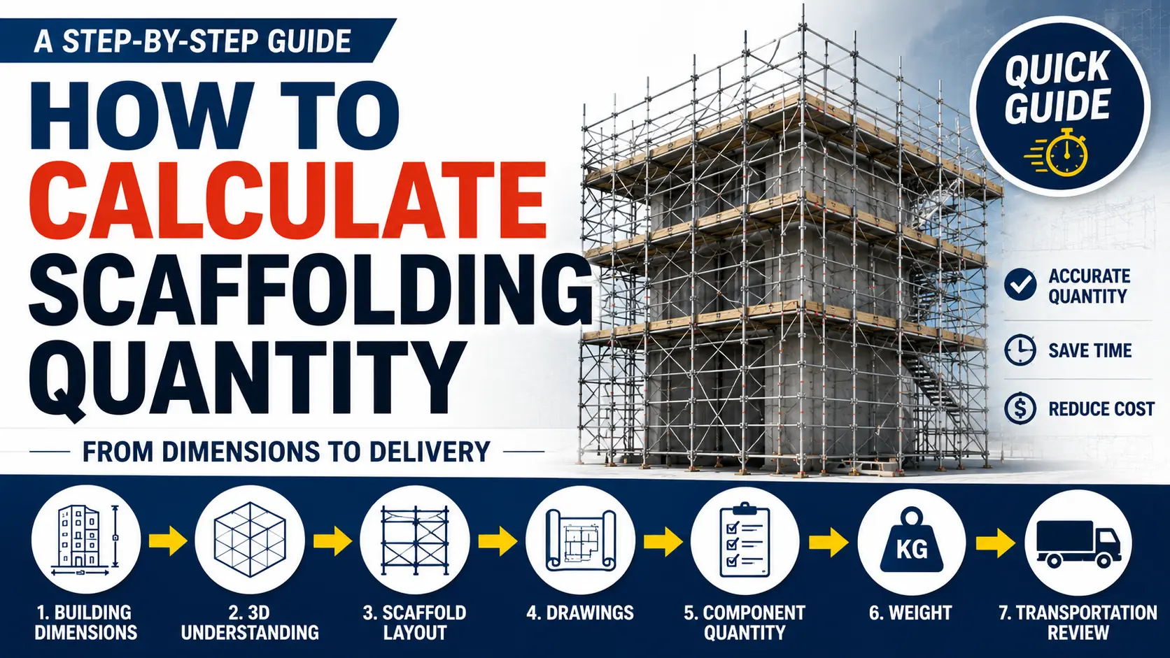
- How to Calculate Scaffolding Quantity: A Step-by-Step Guide — A broader guide to scaffold quantity calculation before quantities are organized into a BOM.
- Scaffold Ties Explained: Types, Spacing & Layout — Useful when reviewing whether tie quantities correspond to the intended and feasible layout.
- Scaffold Plan vs Elevation vs Section: What Each Drawing Shows — Helps explain why BOM verification should not rely on a single drawing view.


Key Takeaways
An accurate scaffolding BOM is not simply a spreadsheet containing component totals.
It should maintain a clear relationship between:
Drawings → Physical Scaffold → Component Types → Quantities → Site Conditions → Material Availability
The most important checks are often found where these pieces of information meet.
In practical scaffold planning, pay particular attention to:
- differences between inner and outer guardrail arrangements,
- actual tie locations,
- drawing and site revisions,
- corner double-counting,
- correct standard and component types,
- and the difference between required materials and currently available stock.
The goal is not just to make the numbers add up.
The goal is to create a material list that accurately represents the scaffold being planned and that can be checked against the information on which that scaffold is based.
Conclusion
A scaffolding BOM should be treated as the final organized representation of the materials required by the planned scaffold, not simply as a spreadsheet of totals.
The most reliable BOMs maintain traceability from the current drawings to the physical scaffold arrangement, component types and sizes, calculated quantities, actual site conditions and material availability. Particular care is needed at interfaces such as corners, changes in geometry, inner and outer guardrail conditions, tie locations and drawing revisions.
Before a BOM is released for planning, allocation or procurement, it should therefore be checked against the latest approved project information and the scaffold arrangement it is intended to represent.
Official References
The following official sources support the general scaffold-planning, design, tie, stability, guardrail and manufacturer-instruction principles referenced in this article. They do not replace project-specific design information, local regulations or manufacturer requirements.
- Health and Safety Executive (HSE), Great Britain — “Scaffolds”
https://www.hse.gov.uk/construction/safetytopics/scaffoldinginfo.htm
Supports the need to coordinate scaffold design with site information, drawings, restrictions on tie locations, manufacturer instructions, bracing, ties, stability and project-specific conditions.
- Occupational Safety and Health Administration (OSHA), United States — 29 CFR 1926.451, “General requirements”
https://www.osha.gov/laws-regs/regulations/standardnumber/1926/1926.451
Supports U.S.-specific requirements concerning scaffold design, supported-scaffold stability, ties, braces, platforms and guardrail systems.
Article updated: October 28, 2026. Original publication date: see the WordPress post date.
Last Verified
Last Verified: September 2026
Regulations, official guidance and manufacturer documentation may change. Always confirm the current requirements applicable to the project location, scaffold system and intended use.
This article is general technical information and is not a substitute for project-specific engineering, applicable law, contract documents, project specifications, manufacturer instructions or competent professional review.
About the Author
ISHIDA DESIGN OFFICE brings practical experience in Japan since 1998, specializing in scaffolding design, temporary works planning, CAD drafting, quantity estimation, and construction support.
Drawing on experience from residential, commercial, and industrial projects, he shares practical insights that emphasize not only sound engineering design but also buildability, safety, and real-world jobsite application.
At Scaffold Design Hub, he combines practical experience from Japan with official guidance and technical resources from government agencies, manufacturers, and industry organizations around the world to provide reliable, practical information for construction professionals.
To learn more, visit the About page. For questions or project inquiries, please use the Contact page.