Scaffold load capacity is often discussed as if it were a single number: “How much weight can this scaffold hold?”
In practice, that question is too simple.
A scaffold must support its own weight, the people and materials placed on it, and loads created by environmental conditions such as wind. Just as importantly, a designer needs to understand where those loads act and how they are transferred through the scaffold structure.
A working platform may have an allowable load, but that does not mean every component below it can automatically support any arrangement of that load. Standards, ledgers, transoms, brackets, ties, braces, base components and the supporting ground or structure all form part of the load path.
This is why scaffold load capacity should be considered as a system rather than as a single kilogram or pound value.
I have worked in scaffold and formwork support design in Japan since 1998. One principle I consider particularly important is that the designer must understand what work will actually be carried out on the scaffold before assessing the loads. A scaffold used mainly for access is not necessarily subjected to the same loading conditions as one used to support workers, tools, stored materials or lifting operations.
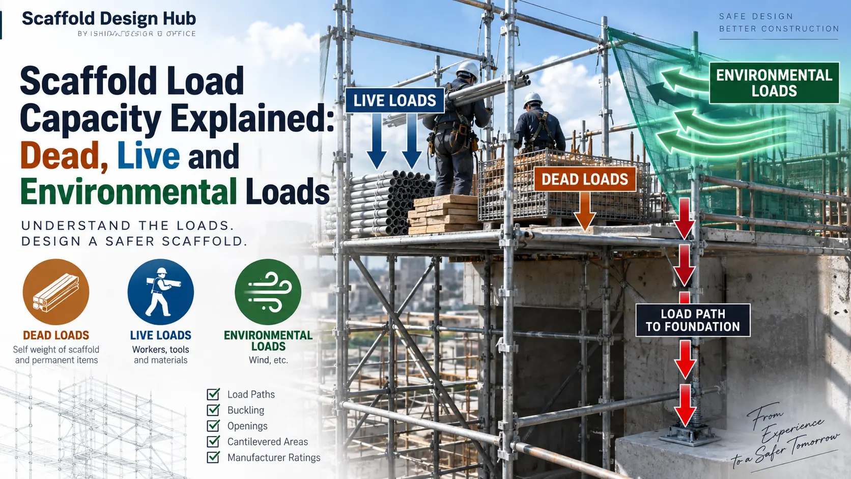
This guide explains the three fundamental categories of scaffold loading—dead loads, live loads and environmental loads—and shows how designers should think about load paths, concentration, buckling, openings and cantilevered areas.
IMPORTANT: This article explains general design principles. Actual allowable loads and design requirements depend on the scaffold system, manufacturer data, configuration, applicable standards and regulations, site conditions and intended use. Always verify the requirements applicable to the actual scaffold being designed.
What Does Scaffold Load Capacity Mean?
Scaffold load capacity describes the ability of a scaffold, or an individual scaffold component, to safely resist the loads applied or transmitted to it under the relevant design conditions.
The important words here are applied or transmitted.
Loads placed on a working platform do not remain on that platform. They travel through the supporting members and eventually into the foundation, supporting structure or ground.
Workers and materials → platform → supporting horizontal members → standards → base components → supporting ground or structure
The actual load path can become considerably more complicated where a scaffold contains:
- brackets,
- loading bays,
- openings,
- bridging members,
- cantilevered sections,
- multiple working lifts,
- hoists or lifting equipment,
- changes in bay geometry,
- or other non-standard arrangements.
For this reason, the capacity of one component should not be confused with the capacity of the scaffold as a whole.
This distinction is also reflected in OSHA requirements. Under 29 CFR 1926.451, scaffold components must be capable of supporting their own weight and the required multiple of the maximum intended load applied or transmitted to that component. The regulation also requires scaffolds to be designed by a qualified person and loaded in accordance with that design.
The Three Main Types of Scaffold Loads
For a basic understanding of scaffold loading, it is useful to divide loads into three broad categories:
- Dead loads
- Live loads
- Environmental loads
These categories help designers identify where loads originate.
However, identifying the type of load is only the beginning. The designer must then consider how the load acts on the scaffold and how it travels through the structure.
1. Dead Loads
A dead load is generally the permanent or relatively constant weight associated with the scaffold structure itself and components that remain installed.
Depending on the scaffold configuration, dead load may include the weight of:
- standards,
- ledgers,
- transoms,
- frames,
- working platforms or decks,
- guardrails,
- toe boards,
- brackets,
- braces,
- stair units,
- ladders,
- loading-bay components,
- and other permanently installed scaffold components.
As the scaffold becomes taller, the cumulative self-weight carried by the lower parts of the structure can become increasingly important.
The load acting on a lower standard is not necessarily the same as the load acting on a standard near the top of the scaffold.
Lower components may receive loads transmitted from multiple levels above them.
Therefore, designers should not look only at the weight of individual components. They need to understand how the complete scaffold configuration transfers its dead load downward.
2. Live Loads
Live loads are loads that can change during scaffold use.
Typical examples include:
- workers,
- tools,
- construction materials,
- equipment,
- materials temporarily stored on working platforms,
- and other loads associated with the work being performed.
This is where understanding the intended use of the scaffold becomes essential.
Before assessing scaffold loading, a designer should know what type of work will take place.
- Will the scaffold mainly provide access?
- Will workers carry hand tools?
- Will cladding, masonry materials or other construction materials be stored on the platform?
- Will materials be lifted onto a loading area?
- Will several working levels be used simultaneously?
These questions can materially change the design conditions.
My Practical Approach
From my experience in scaffold design, I do not think it is sufficient to begin with a generic platform load and assume that it represents the actual site condition.
The designer should first understand what work will be carried out and what is realistically expected to be placed on the scaffold.
The same scaffold geometry can be subjected to very different loading conditions depending on its intended use.
If the load conditions are unclear, they should be clarified rather than simply assumed.
Manufacturer-Rated Capacity Must Be Verified
Another fundamental distinction is the difference between:
- the load expected in the design, and
- the rated or allowable capacity of the actual scaffold components and system.
These are not interchangeable.
The designer needs to verify the technical information for the scaffold system and components actually being used.
Manufacturer documentation may define rated capacities, allowable loads, configuration limits and other conditions that affect how components can be used.
A value taken from another scaffold system, another component or a generic reference should not automatically be assumed to apply.
OSHA likewise states that scaffolds and scaffold components must not be loaded beyond their maximum intended loads or rated capacities, whichever is less.
For manufactured systems, the manufacturer’s technical data should therefore be treated as an important part of the design information.
Load Distribution Matters as Much as Total Weight
Consider two working platforms carrying the same total amount of material.
On the first platform, the material is spread relatively evenly.
On the second, most of the material is concentrated in a small area.
The total weight may be identical, but the effect on individual supporting members can be very different.
This is the difference between thinking only about total load and thinking about load distribution.
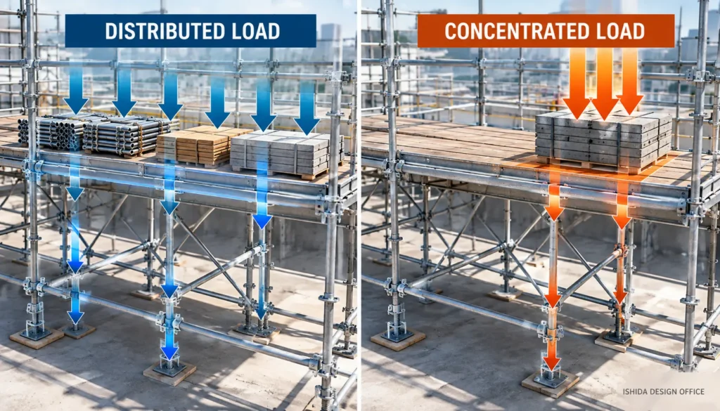
Designers should consider:
- where materials will be placed,
- how large the loaded area will be,
- whether loads may become concentrated,
- which members directly support the loaded area,
- and where those loads will travel next.
This becomes especially important around loading areas, brackets, openings and other locations where the structural arrangement differs from the regular scaffold bays.
Understanding the Load Path
A scaffold should be viewed as a connected structural system.
Suppose materials are placed on a working platform.
The load may first be carried by the deck, then transferred into supporting horizontal members, then into standards, and finally into the bases and supporting surface.
In a regular scaffold arrangement, that path may be relatively straightforward.
But if the scaffold contains an opening, bracket or cantilever, the load path changes.
Where does this load go next?
Following the load through the structure is more meaningful than looking at one component in isolation.
Buckling Requires Particular Attention
Standards and other compression members do not fail only because a material has reached a simple compressive strength limit.
Long, slender compression members can also be vulnerable to buckling.
Buckling behavior is influenced by factors such as:
- member geometry,
- effective unsupported length,
- restraint conditions,
- connection conditions,
- applied axial force,
- eccentricity,
- and the overall scaffold configuration.
For scaffold designers, this means that checking a nominal load value alone may not be sufficient.
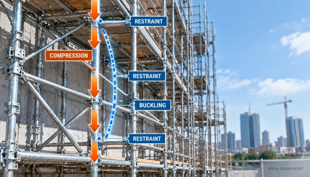
A Practical Design Principle
In my design work, I consider it important to understand the actual loading condition and pay particular attention to the stability of members subjected to compression.
The designer should not assume that a standard is acceptable simply because a load appears to be below a single published number. The actual configuration and the manufacturer’s technical requirements need to be considered.
The purpose here is not to provide a universal buckling calculation—because the required method depends on the scaffold system, member properties and applicable design rules—but to highlight that compression stability must not be overlooked.
Openings Can Change the Load Path Completely
Openings are one of the areas where load transfer deserves special attention.
Scaffold openings may be required for:
- building entrances,
- vehicle access,
- material movement,
- pedestrian routes,
- equipment access,
- or other site requirements.
In a regular scaffold, vertical loads can normally continue downward through a relatively continuous arrangement of standards.
An opening interrupts that arrangement.
Loads from the scaffold above the opening may therefore need to be transferred across the opening and into supporting members or standards at its sides.
This can create substantially different forces from those in a regular bay.
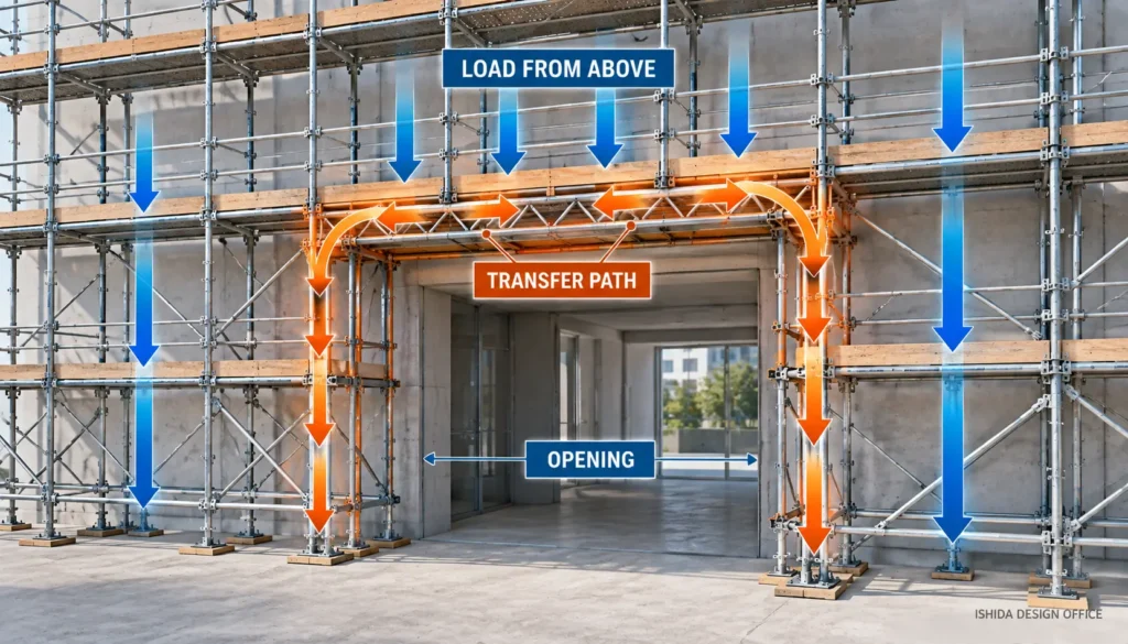
What I Check Around Openings
From my practical design experience, an opening should not be treated simply as “removing a standard.”
The important question is whether all relevant loads from the scaffold above the opening can be safely transferred through the structure around the opening.
That requires consideration of the load path and the capacities of the members involved.
The exact solution depends on the scaffold system, opening geometry, loading condition, manufacturer requirements and applicable design criteria. For that reason, non-standard openings may require a specific structural assessment rather than an assumption based on a typical bay.
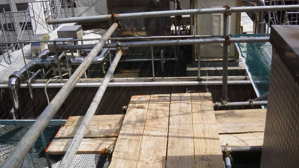
Cantilevered Areas Require Special Assessment
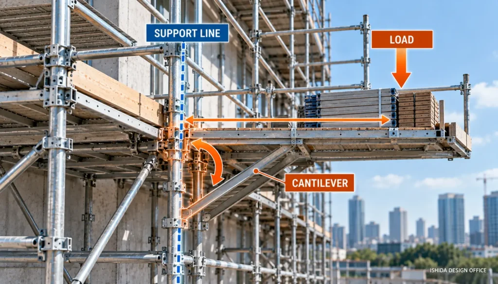
Cantilevered or bracket-supported areas are another situation where simple load assumptions can become dangerous.
A cantilever places load away from the primary support line.
This can introduce:
- bending,
- eccentric loading,
- increased reactions,
- overturning effects,
- and additional forces in connected scaffold components.
The farther a load acts from its support, the more important its position can become.
OSHA specifically recognises eccentric loading in supported scaffolds and requires measures such as ties, guys, braces or outriggers to prevent tipping where applicable.
My Rule for Cantilevered Loading
DO NOT ASSUME: In my design practice, I treat cantilevered loading as a condition that requires positive verification.
I do not consider it sufficient to assume that because the main scaffold is adequate, a projecting portion is automatically adequate as well.
The load, support condition and resulting forces need to be assessed, and the safety of the arrangement must be confirmed using the appropriate design calculation and the relevant system information.
The exact calculation method is outside the scope of this article and depends on the scaffold system and applicable design requirements.
3. Environmental Loads
Scaffolds are also exposed to loads that do not come from workers or materials.
These are commonly described as environmental loads.
Depending on the location, scaffold configuration and applicable design rules, environmental effects may include:
- wind,
- snow,
- ice,
- rain-related effects,
- and other site-specific environmental conditions.
Among these, wind is particularly important for many external scaffolds.
Wind Loads on Scaffolding
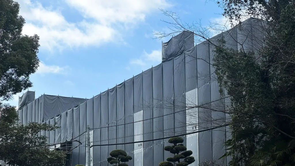
An open scaffold and a scaffold covered with sheeting do not necessarily behave the same way in wind.
Sheeting, tarpaulins, debris containment and some types of netting can significantly change how wind acts on the scaffold.
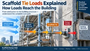
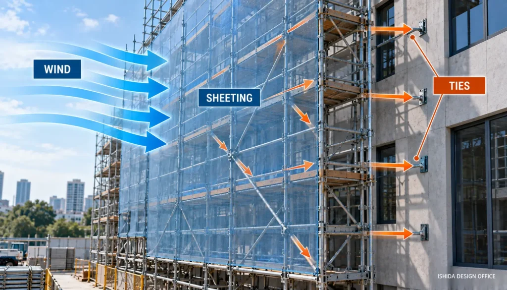
The wind force must then be resisted and transferred through the scaffold’s lateral stability system and ultimately into suitable supports or the supporting structure.
This is one reason why ties and bracing cannot be considered separately from environmental loading.
The UK Health and Safety Executive specifically warns that sheeting increases the effect of wind on scaffolding and the load transferred to the building. It also advises that those responsible for the scaffold design should be informed before sheeting or debris netting is attached.
OSHA similarly requires a scaffold using wind screens to be secured against the anticipated wind forces.
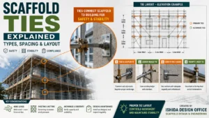
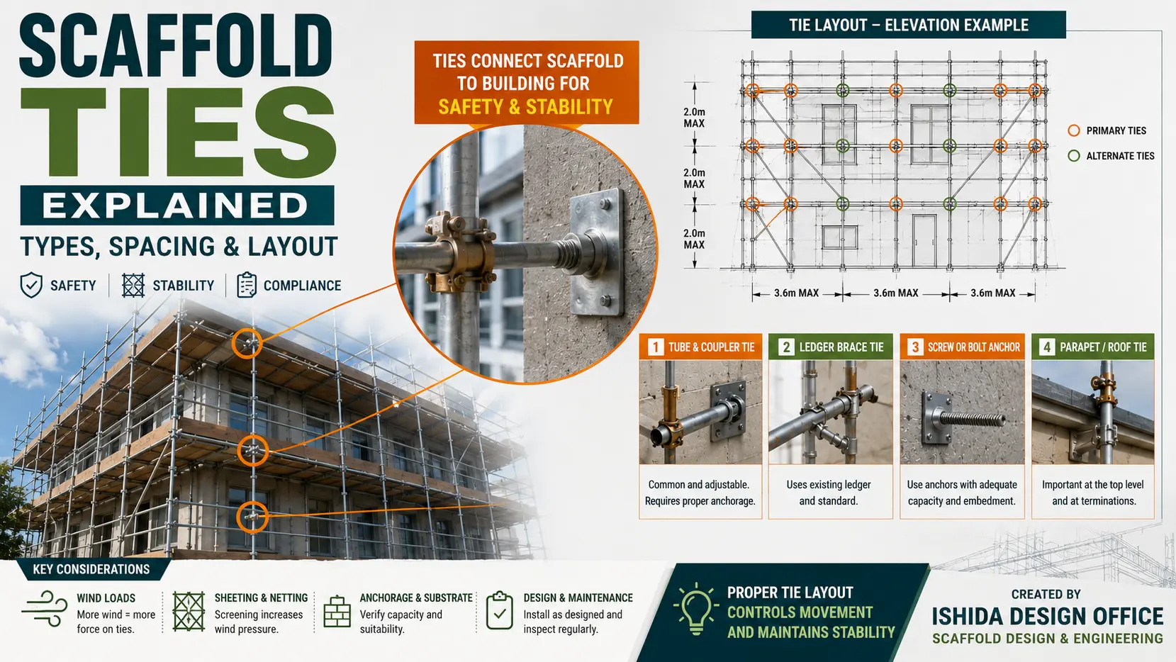
Why Scaffold Ties Matter Under Environmental Loading
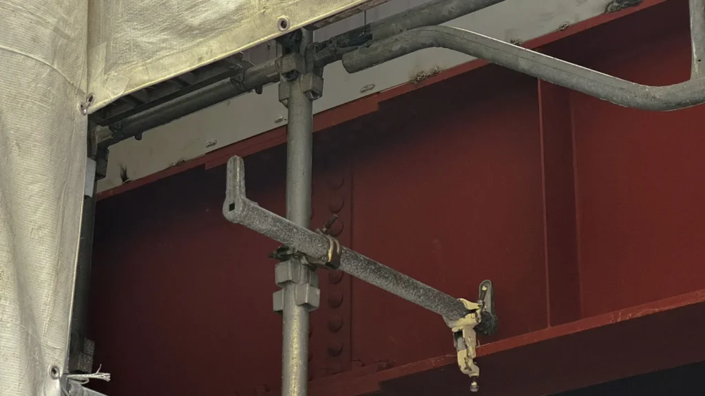
Scaffold ties provide an important connection between many supported scaffolds and the building or supporting structure.
Their design cannot be reduced to simply drawing a regular grid of tie symbols.
The designer needs to consider:
- the scaffold geometry,
- tie locations,
- actual attachment possibilities,
- the supporting building or structure,
- wind conditions,
- sheeting or netting,
- manufacturer requirements,
- and applicable standards.
A theoretically regular tie pattern is of little value if the ties cannot actually be installed at those locations.
For a more detailed discussion, see Scaffold Ties Explained: Types, Spacing & Layout.
Bracing and Overall Stability
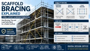
Bracing performs a different function from ties, although both contribute to scaffold stability.
Bracing helps maintain scaffold geometry and resist movements and forces within the scaffold structure.
It should therefore be considered as part of the complete load-resisting system rather than as an isolated accessory.
Openings, access bays, stair towers and other interruptions can affect normal bracing arrangements, so their interaction with the complete scaffold configuration needs to be checked.

For more detail, see Scaffold Bracing Explained: Types, Layout & Design Principles.
The Supporting Ground or Structure Is Part of the Load Path
The load path does not end at the bottom of the scaffold standard.
Loads must ultimately be transferred into something capable of supporting them.
That may be:
- ground,
- concrete,
- a floor slab,
- a roof,
- a structural member,
- or another supporting structure.
A scaffold can have adequately rated components and still have a serious problem if the supporting surface cannot resist the reactions delivered to it.
The condition of the base should therefore be considered together with the scaffold loading.
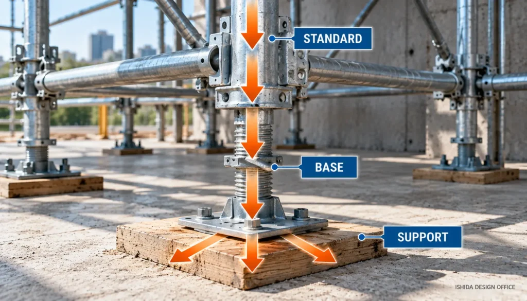
This is especially important where:
- ground conditions vary,
- the scaffold stands on an existing structure,
- loads are concentrated,
- support conditions change along the scaffold,
- or unusually high reactions are expected.
Multiple Working Levels Can Change the Design Condition
Another common mistake is to think only about one working platform.
A tall scaffold may contain many boarded lifts, but that does not automatically mean every level can be loaded to its maximum individual capacity simultaneously.
The intended number of working levels and their expected loads need to be established as part of the design conditions.
HSE guidance specifically identifies both the number of boarded lifts and the maximum working loads as information that should be provided during scaffold planning.
The designer therefore needs to distinguish between:
- what one platform can carry,
- what individual components can carry,
- and what the complete scaffold configuration is designed to carry.
These are related—but they are not the same question.
Dead, Live and Environmental Loads Work Together
Dead, live and environmental loads are useful categories for understanding where loads originate.
But a real scaffold does not experience them as three completely separate structures.
A standard may simultaneously be affected by:
- scaffold self-weight,
- loads transmitted from workers and materials,
- forces resulting from eccentric loading,
- and forces associated with environmental conditions.
The design therefore needs to consider the applicable load cases and combinations required by the relevant design rules.
There is no single universal equation that can safely replace the requirements of the scaffold system, manufacturer and applicable standard.
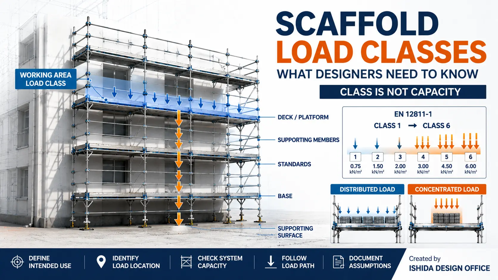
Load Capacity Is Not the Same as Load Class
The terms load capacity and load class are related, but they should not be treated as synonyms.
A load class typically describes an intended working-platform loading category under a particular standard or guidance system.
Load capacity can refer more broadly to the ability of a component, platform or scaffold configuration to resist a particular load.
For example, knowing the load class of a working platform does not by itself answer every structural question about:
- standards,
- brackets,
- ties,
- bridging members,
- foundations,
- or cantilevered sections.
For a detailed explanation of this distinction, read Scaffold Load Classes Explained: What Designers Need to Know.
Five Load Questions I Consider Essential
After many years of scaffold and formwork support design, I find it useful to reduce the initial load assessment to five fundamental questions:
- What will the scaffold actually be used for?
Identify the work, workers, tools, materials, equipment and other foreseeable loads. - What capacities and limitations apply to the actual scaffold system?
Verify the relevant manufacturer data rather than assuming a generic value applies. - How are the loads transferred through the scaffold?
Follow the load path and pay particular attention to compression-member stability and buckling. - Are there openings or other interruptions in the normal load path?
Confirm that loads from above can be safely transferred around the opening. - Are there cantilevered, bracketed or eccentrically loaded areas?
Do not assume the regular scaffold capacity automatically applies. These areas should be specifically assessed and, where required, verified by calculation.
These questions do not replace structural calculations. They help define what the calculation actually needs to represent.
Common Scaffold Load Capacity Mistakes
Mistake 1: Asking Only “How Many Kilograms Can It Hold?”
There is rarely one useful answer for an entire scaffold.
The platform, standards, horizontal members, brackets and other components may have different structural roles and limitations.
Mistake 2: Using a Manufacturer Rating Without Checking the Configuration
Manufacturer information must be read in the context of the actual component, system and permitted configuration.
Mistake 3: Ignoring Load Concentration
A distributed load and a concentrated load of the same total weight can produce very different effects.
Mistake 4: Ignoring Loads From Multiple Working Levels
Loads from upper levels can be transmitted into lower standards and supporting components.
Mistake 5: Treating an Opening Like a Normal Bay
Removing or interrupting the normal support arrangement changes the load path.
Mistake 6: Assuming a Cantilever Is Safe Because the Main Scaffold Is Safe
Cantilevers introduce different structural effects and should be assessed accordingly.
Mistake 7: Ignoring Sheeting and Wind
Adding sheeting or netting can significantly change environmental loading.
Mistake 8: Looking at the Scaffold but Not Its Support
The base, ground or supporting structure must also be capable of receiving the scaffold reactions.
A Better Scaffold Load Design Workflow
A sound load assessment begins before calculation.
First, establish the scaffold’s intended use.
Then identify the loads that can reasonably occur during that use.
Next, understand where those loads act.
After that, trace how the loads are transferred through the scaffold.
Then verify that the relevant components and system configuration have the required capacities under the applicable manufacturer information, standards and regulations.
Finally, pay particular attention to locations where the normal structural arrangement changes, including:
- openings,
- loading bays,
- brackets,
- cantilevers,
- changes in geometry,
- lifting points,
- multiple loaded levels,
- and unusual support conditions.
This approach connects the calculation to the scaffold that will actually be used.
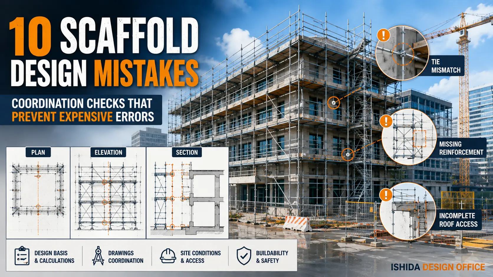
How Scaffold Drawings Help With Load Assessment
A good scaffold drawing is more than an erection layout.
It helps the designer understand the structural configuration.
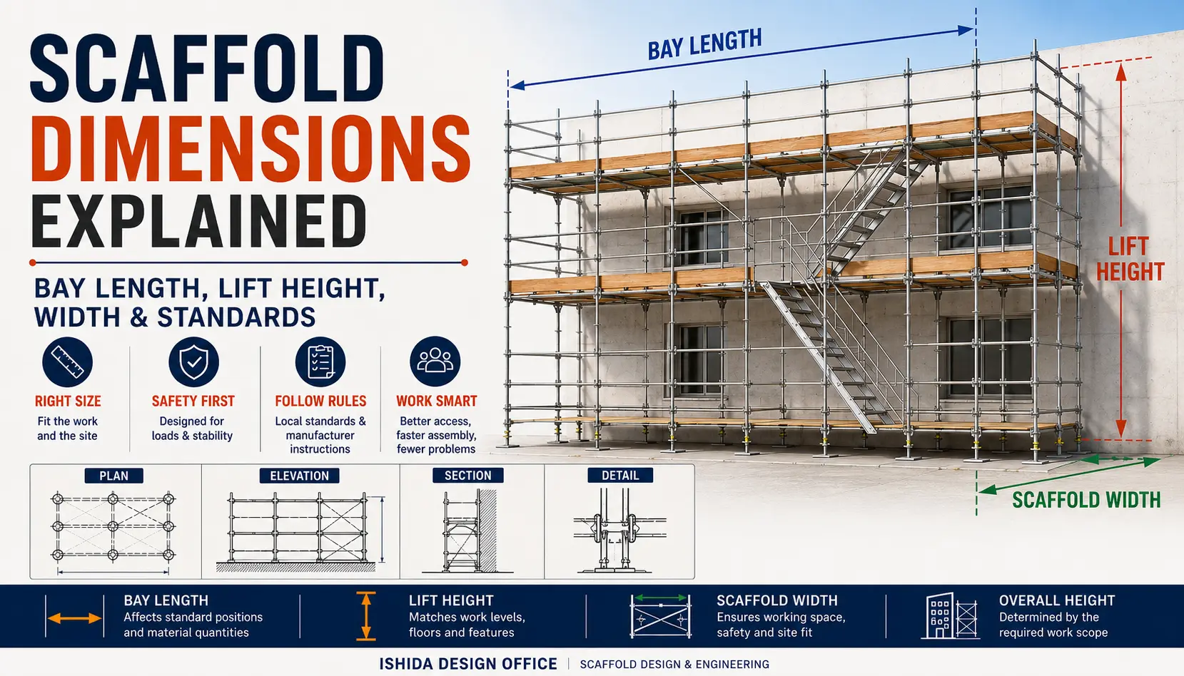
The plan can show:
- bay arrangement,
- scaffold width,
- brackets,
- projections,
- openings,
- and relationships with the building.
The elevation helps show:
- lift arrangement,
- scaffold height,
- openings,
- tie positions,
- bracing,
- and changes in vertical configuration.
The section can be especially useful for understanding:
- offsets,
- brackets,
- cantilevers,
- working-platform positions,
- relationships with the building,
- and load paths that may not be obvious in plan.
Original CAD Elevation: Reviewing Scaffold Geometry Before Load Assessment
The following CAD elevation is an example of scaffold drawing work by ISHIDA DESIGN OFFICE. I use elevation drawings to review the arrangement of scaffold lifts, the continuity of supporting members and changes in geometry before considering whether a particular loading assumption is appropriate. A complex building outline makes it especially important to coordinate the elevation with the plan and relevant sections.
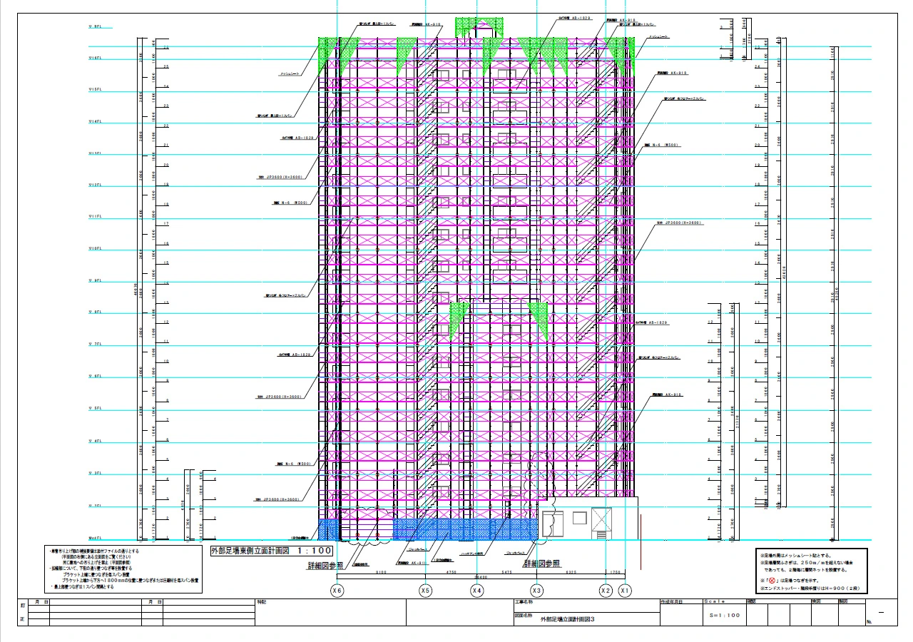
What this drawing can—and cannot—tell us: An elevation can help identify where the vertical arrangement changes and where additional load-path checks may be needed. It cannot confirm actual leg reactions, platform capacities, tie forces or foundation adequacy on its own. Those checks require the relevant load assumptions, manufacturer information, support conditions and project-specific calculations, with the plan and sections reviewed alongside the elevation.
For more detail, see How to Read Scaffold Drawings: Plan, Elevation, Section & Details and Scaffold Plan vs Elevation vs Section: What Each Drawing Shows.
Practical Scaffold Load Checklist
Before finalising a scaffold load assessment, designers should be able to answer the following questions:
- ☑ What work will be performed from the scaffold?
- ☑ How many workers may use it?
- ☑ What tools, equipment and materials may be placed on it?
- ☑ Could materials become concentrated in one area?
- ☑ Will multiple working lifts be used at the same time?
- ☑ Are there loading bays or lifting operations?
- ☑ What are the relevant manufacturer-rated capacities and limitations?
- ☑ How does each significant load travel through the scaffold?
- ☑ Are compression members adequately assessed for their actual configuration?
- ☑ Are there openings that interrupt the normal load path?
- ☑ Are there brackets, cantilevers or eccentric loads?
- ☑ Will sheeting, netting or other coverings be installed?
- ☑ Have environmental loads been considered where applicable?
- ☑ Are ties and bracing appropriate for the design conditions?
- ☑ Can the ground or supporting structure safely receive the reactions?
- ☑ Does the final scaffold drawing match the assumptions used in the structural assessment?
If one of these questions cannot be answered, additional information may be required before the design can be properly assessed.
Frequently Asked Questions
How much weight can a scaffold hold?
There is no single universal scaffold load capacity. The answer depends on the scaffold system, components, configuration, manufacturer data, platform arrangement, load distribution, intended use and applicable standards or regulations.
What is dead load in scaffolding?
Dead load generally includes the self-weight of the scaffold and components that remain installed, such as standards, ledgers, platforms, guardrails, braces and other fixed scaffold elements.
What is live load on a scaffold?
Live load generally includes variable loads associated with scaffold use, such as workers, tools, equipment and construction materials.
Is wind considered a scaffold load?
Yes. Wind can create significant forces on external scaffolds, particularly when sheeting, tarpaulins or netting increase the area exposed to wind.
Can I use the manufacturer’s maximum platform load for the entire scaffold?
Not automatically. A platform rating does not by itself establish the capacity of every standard, bracket, tie, support or other component in the complete scaffold.
Why are scaffold openings important in load calculations?
An opening can interrupt the normal vertical load path. Loads from the scaffold above may need to be transferred around the opening through other members and into adjacent supports.
Why are cantilevered scaffold sections different?
Cantilevered sections introduce loads away from the main support line and can create bending, eccentric forces and overturning effects. They require specific consideration rather than an assumption based on the regular scaffold bays.
Does every scaffold require a bespoke structural calculation?
Not necessarily. Requirements depend on the scaffold type, configuration, manufacturer’s instructions and applicable local regulations or standards. For example, HSE guidance in Great Britain distinguishes recognised standard configurations from scaffolds requiring bespoke calculation. Requirements in other jurisdictions may differ.
Related Topics
- Scaffold Load Classes Explained: What Designers Need to Know
- Scaffold Ties Explained: Types, Spacing & Layout
- Scaffold Bracing Explained: Types, Layout & Design Principles
- How to Read Scaffold Drawings: Plan, Elevation, Section & Details

Key Takeaways
- Scaffold load capacity is not one universal number.
- Dead, live and environmental loads need to be considered in relation to the actual scaffold configuration.
- Manufacturer-rated capacities must be checked for the system and components actually used.
- Load paths and load concentration matter, especially around openings and cantilevered areas.
- Ground or support conditions, ties, bracing and environmental effects form part of the overall structural assessment.
Conclusion
Understanding scaffold load capacity starts with understanding how the scaffold will actually be used.
Dead loads tell us what the scaffold itself contributes.
Live loads tell us what workers, tools, materials and operations add.
Environmental loads tell us what forces the surrounding environment can impose.
But the designer’s job does not stop at identifying those three categories.
Where does the load act?
Where does it go?
Which components receive it?
Does the actual scaffold configuration have the capacity to transfer it safely?
In my experience, these questions become especially important around load concentrations, compression members, openings and cantilevered areas.
A scaffold should therefore not be judged by one load-capacity number alone. Its intended use, actual configuration, manufacturer data, load path, environmental conditions and supporting structure all need to be considered together.
That is the difference between simply knowing a load value and understanding how a scaffold carries load.
Official References
The regulatory and technical requirements for scaffolding vary by country, scaffold system, configuration and intended use. The following official sources were used to support the general load-capacity and scaffold-design principles discussed in this article.
U.S. Occupational Safety and Health Administration (OSHA)
29 CFR 1926.451 — Scaffolds: General Requirements
This regulation covers scaffold capacity, maximum intended loads, rated capacities, scaffold design and loading requirements in the United States. In particular, it requires scaffold components to have sufficient capacity for their own weight and the maximum intended loads applied or transmitted to them, subject to the specific provisions of the regulation.
UK Health and Safety Executive (HSE)
Scaffolds — Construction Safety Guidance
Health and Safety Executive — Scaffolds
This guidance explains scaffold planning and design requirements in Great Britain, including intended use, maximum working loads, number of working platforms, sheeting and netting, ground and supporting-structure conditions, manufacturer instructions and circumstances in which a bespoke scaffold design and calculation may be required.
Last Verified: September 2026
Regulations, official guidance and manufacturer documentation may change. Always confirm the current requirements applicable to the project location, scaffold system and intended use.
This article is general technical information and is not a substitute for project-specific engineering, applicable law, contract documents, project specifications, manufacturer instructions or competent professional review.
About the Author
ISHIDA DESIGN OFFICE brings more than 30 years of practical experience in Japan, specializing in scaffolding design, temporary works planning, CAD drafting, quantity estimation, and construction support.
Drawing on experience from residential, commercial, and industrial projects, he shares practical insights that emphasize not only sound engineering design but also buildability, safety, and real-world jobsite application.
At Scaffold Design Hub, he combines practical experience from Japan with official guidance and technical resources from government agencies, manufacturers, and industry organizations around the world to provide reliable, practical information for construction professionals.
To learn more, visit the About page. For questions or project inquiries, please use the Contact page.