A scaffold plan, elevation and section can communicate most of a scaffold arrangement—but not always enough to build, check or understand every part of it.
Local conditions such as openings, projections, brackets, changes in level, unusual support arrangements or difficult building interfaces may require additional information.
That is where a scaffold detail drawing becomes useful.
The purpose of a detail is not to make the drawing set look more technical. It is to remove ambiguity where the main drawings cannot communicate a specific condition clearly enough.
There is also an opposite problem: adding too many details.
A drawing set containing numerous overlapping details can become harder rather than easier to understand if dimensions, member arrangements or notes begin to contradict one another.
The real question is not how many details a scaffold drawing contains, but where additional information is needed to communicate the design clearly and consistently.
This article explains how to make that distinction.
What Is a Scaffold Detail Drawing?
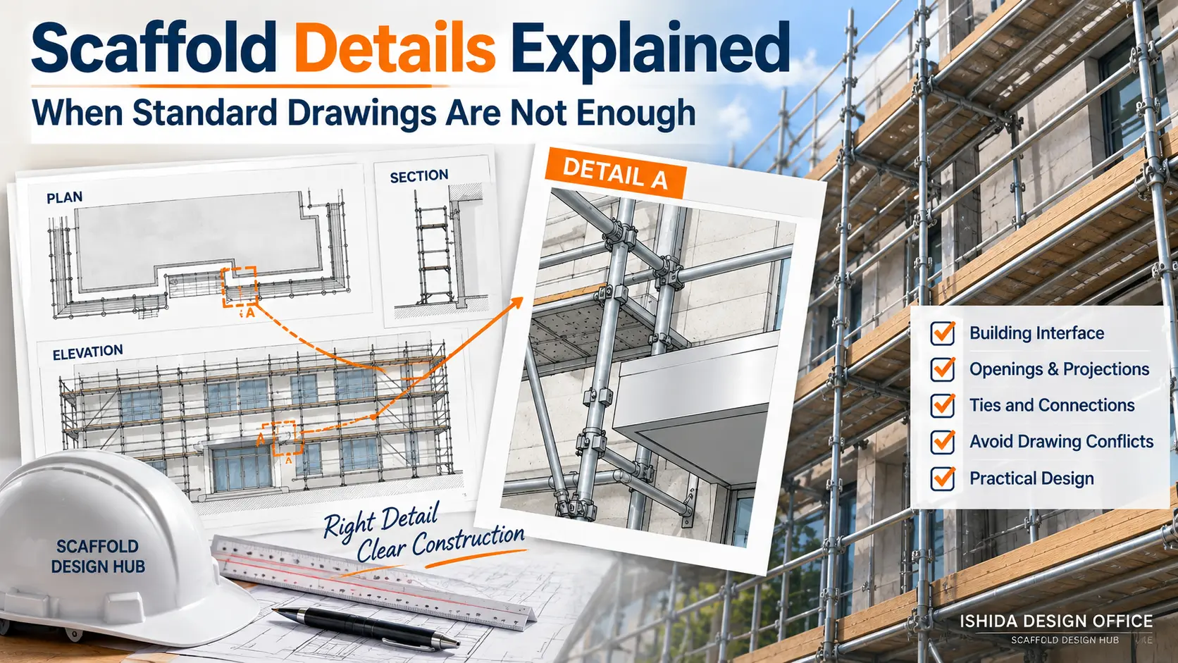
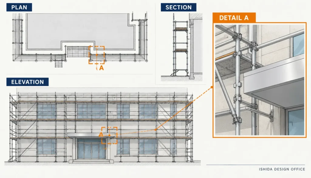
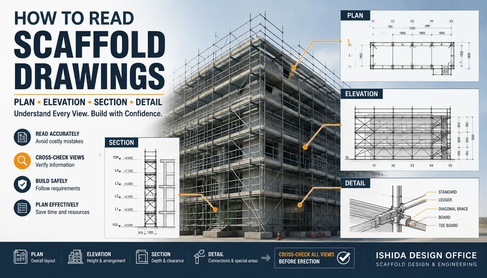
A scaffold detail drawing is an enlarged or focused representation of a specific part of the scaffold that cannot be communicated adequately through the general plan, elevation or section alone.
The main drawings explain the overall arrangement.
A detail explains a particular condition.
For example, a general elevation may show the complete façade scaffold, while a separate detail may be needed to clarify the relationship between the scaffold and a local building projection.
Similarly, a plan may show the position of an opening but not provide enough information to explain the scaffold arrangement immediately around it.
The detail should therefore answer a specific technical or construction question.
If it does not, its value should be questioned.
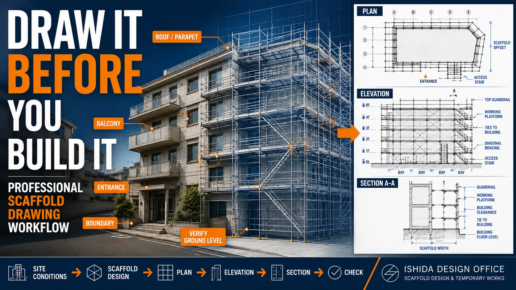
For the wider drawing workflow, see How to Create a Scaffold Drawing: Step-by-Step Design Workflow.
Why Standard Scaffold Drawings Are Sometimes Not Enough
Plan, elevation and section drawings each communicate different information.
A plan is particularly useful for understanding horizontal geometry, scaffold position, building outlines, corners, offsets and access locations.
An elevation communicates the vertical arrangement, including lifts, platforms, façade relationships and many stability components.
A section helps explain the relationship between the building and scaffold across its width, including platform positions, building clearances and changes in geometry.
Together, these views can communicate a large amount of information.
But construction sites are not perfectly repetitive geometric environments.
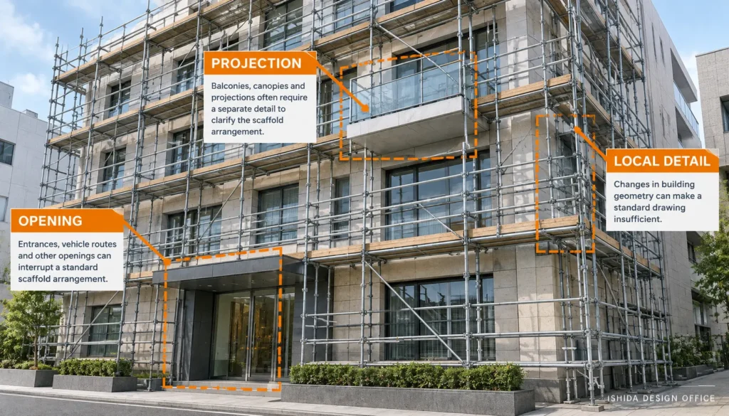
A façade may contain balconies, canopies, entrances, equipment, roof changes, recesses, projections and restricted attachment areas.
Trying to show every local condition on the main drawings can eventually make those drawings difficult to read.
A focused detail can be a better communication tool.
When Does a Scaffold Need a Detail Drawing?
There is no useful universal rule stating that every particular condition always requires a separate detail.
The decision depends on the scaffold, project documentation, scaffold system, site conditions and applicable requirements.
However, several situations should make the designer consider whether the standard drawing views communicate enough information.
Unusual Building Geometry
Corners, recesses, curved surfaces, changes in façade position and other irregular geometry can make a standard repetitive scaffold arrangement difficult to maintain.
A detail may help explain the local relationship between the scaffold and building.
The objective is not to redraw the whole scaffold at a larger scale.
It is to clarify the unusual part.
Openings and Access Routes
Entrances, vehicle routes, pedestrian passages and other openings can interrupt an otherwise regular scaffold arrangement.
They may affect more than geometry.
Depending on the design, they can interact with standards, bracing, platforms, access and other elements.
A detail can help communicate the resolved local arrangement.
This article does not cover how to structurally design bridging or other specialist solutions over openings; those conditions require their own design consideration.
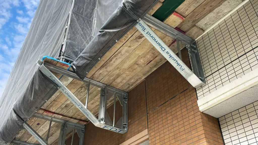
Brackets and Local Extensions
A local platform extension or bracket arrangement can be difficult to understand from a general elevation alone.
The reader may need to understand where the extension occurs, how it relates to the main scaffold and what part of the drawing applies to it.
Where structural verification is required, the detail drawing does not replace that verification.
Roofs, Parapets and Level Changes
Roof edges, parapets and changing building levels often create conditions that are easier to understand in section or local detail than in a large elevation.
The important point is to show the relevant relationship clearly rather than simply adding more lines to the general drawing.
Tie and Building-Interface Conditions
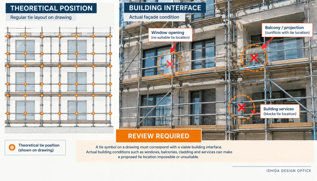
Tie locations deserve particular attention because a tie shown graphically must correspond to something that can actually be achieved at the supporting structure.
Windows, openings, balconies, cladding, projections, services and other building conditions may affect potential attachment locations.
A neat grid of tie symbols is not enough if those locations do not correspond to viable building interfaces.

Other Non-Standard Conditions
Other situations may also require additional detail where the scaffold departs from the normal arrangement.
Use a detail when the standard views do not communicate an important local condition clearly enough.
Do not create one simply because a similar detail appeared on a previous project.
A Detail Drawing Is Not a Structural Calculation
This distinction is fundamental.
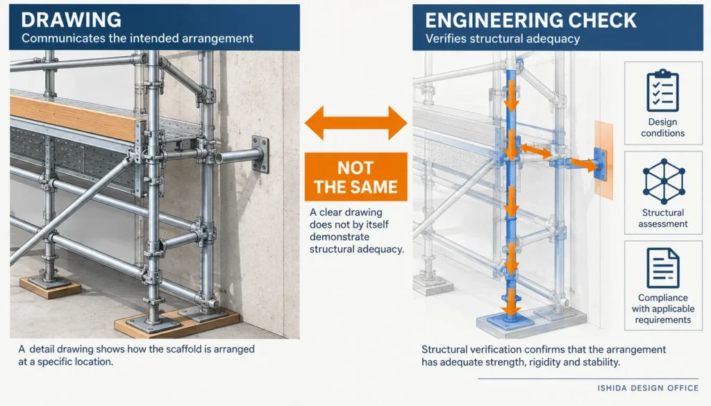
A detail drawing communicates an arrangement.
It does not, by itself, demonstrate that the arrangement has adequate structural capacity.
A drawing can look perfectly logical and still require structural verification.
Where a scaffold falls outside a recognised standard configuration, the UK Health and Safety Executive states that it should be designed by bespoke calculation by a competent person to ensure adequate strength, rigidity and stability.
IMPORTANT: Graphic clarity and structural adequacy are different questions. A designer should not assume that producing a convincing detail has completed the engineering review.
Do Not Automatically Reuse Details from Another Project
After working with scaffold drawings for many years, one principle I consider important is not to assume that a detail from one project can simply be reused on another.
Buildings that appear similar can have different dimensions, façade conditions, openings, support conditions, access requirements and surrounding constraints.
The scaffold system or project requirements may also differ.
A previous detail can sometimes provide a reference for what information may need to be considered, but the new project still needs to be checked against its actual conditions.
This distinction becomes particularly important with unusual details.
The more a detail depends on a specific building interface or site condition, the less appropriate it is to treat it as a universal solution.
Standardisation can improve drawing efficiency. Blind reuse can create design errors.
The Problem with Too Many Detail Drawings
It is easy to assume that more details produce better documentation.
That is not necessarily true.
One problem I have seen in drawing work is that adding too many details can make the drawing set harder to coordinate.
Imagine a project containing:
PLAN → ELEVATION → SECTION → DETAIL A → DETAIL B → DETAIL C
If the same condition is represented several times, every relevant representation needs to remain consistent.
A change to one part of the scaffold may therefore affect several drawings.
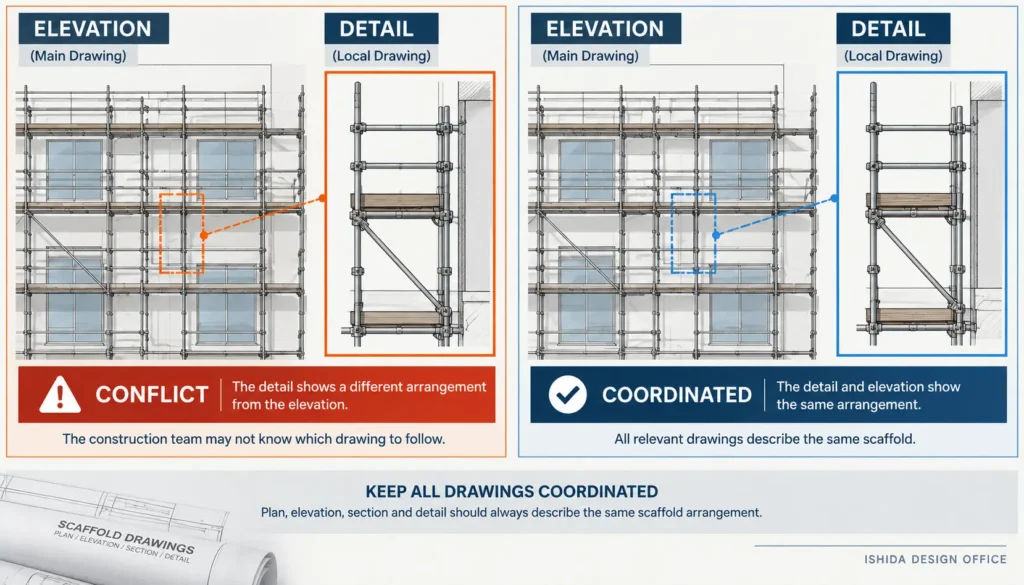
If Detail B shows one arrangement while the elevation still shows the previous arrangement, the drawing set now communicates two different instructions.
The reader then has a practical problem:
Which drawing should be followed?
A good detail should reduce uncertainty.
If unnecessary details multiply the number of places where the same information must be maintained, they may increase uncertainty instead.
The goal should not be maximum drawing quantity. The goal should be minimum ambiguity with sufficient technical information.
Why Scaffold Tie Details Need Particular Attention
Ties are one of the clearest examples of why a detail must relate to the real structure rather than only to the CAD drawing.
A tie symbol can be placed almost anywhere on a drawing.
A physical tie cannot.
The building may contain windows, openings, balconies, cladding, equipment or other conditions that make the proposed location unsuitable or impossible.
HSE guidance emphasizes that scaffolds must be tied or otherwise stabilised appropriately, that ties should remain within their safe working limits, and that proprietary system scaffolds should be tied in accordance with manufacturers’ instructions.
This means the interface between the scaffold and supporting structure deserves real attention.
A Lesson from Practice
In one project I worked on, I received instructions regarding the ties to be incorporated into the scaffold design.
When the proposed arrangement was considered against the actual site condition, those ties could not be installed as intended.
This was not a small drafting inconvenience.
The tie arrangement was connected to the wider scaffold design, so the problem affected more than one isolated detail.
That experience reinforced an important lesson for my drawing work: a tie detail must be checked against the actual building interface, not only against the scaffold geometry.
The specific solution depends on the project and is not something that should be generalised into a universal detail.
The important transferable lesson is the need to verify the interface before relying on the detail.
Real Project Lesson: When a Scaffold Tie Connection Needs a Detail Drawing
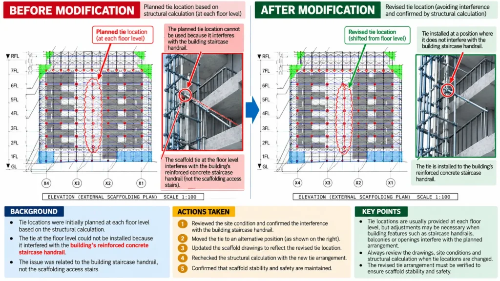
In one of my scaffold design projects in Japan, the original tie positions were arranged at the building’s floor levels based on the structural calculations.
However, a practical review revealed that the planned tie positions interfered with the handrail of an existing reinforced-concrete building staircase.
The tie positions therefore had to be revised to suit the actual building geometry.
This project illustrates an important distinction between an elevation drawing and a connection detail.
The elevation drawing can show where the scaffold ties are located. However, it may not adequately explain how a tie connects to a building element where the surrounding geometry is complicated.
In this case, the revised elevation identified the relocated tie positions, while the accompanying connection detail illustrated the arrangement at the staircase structure.
After revising the arrangement, I updated the scaffold drawings and rechecked the structural calculations.
My practical lesson is that a detail drawing becomes important when the main scaffold drawings cannot clearly communicate the connection arrangement, the relevant building geometry or the information needed to verify the proposed installation.
A detail drawing does not, by itself, establish that a connection is structurally adequate. The connection and supporting building element must also be verified for the actual project conditions.
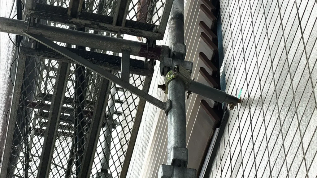
A Tie Symbol Is Not a Real Connection
This sounds obvious, but it is an important drawing principle.
CAD makes it easy to produce regular patterns.
Buildings often make those patterns difficult to achieve.
When reviewing a tie detail, the question is therefore not simply:
“Is the tie shown?”
A better question is:
“Does the drawing correspond with an actual viable attachment condition?”
What Should a Useful Scaffold Detail Communicate?
The exact information depends on what the detail is intended to resolve.
A useful detail may need to communicate:
- the part of the scaffold to which the detail applies;
- relevant geometry and dimensions;
- the relationship between scaffold and building;
- relevant platforms or local components;
- the location of important interfaces;
- references to associated views or notes;
- information necessary to distinguish the local condition from the standard arrangement.
Not every detail needs every item.
The detail should answer the question that caused the detail to be created.
If the detail were removed, what important information would become unclear?
If the answer is “nothing,” the detail may not be necessary.
If removing it would force the scaffolder, supervisor or reviewer to guess an important condition, the detail is probably serving a real purpose.
Detail Drawings Must Agree with the Entire Drawing Set
A detail should never be treated as an isolated sketch.
It belongs to a drawing system.
PLAN ↔ ELEVATION ↔ SECTION ↔ DETAIL ↔ NOTES
These should describe the same scaffold.
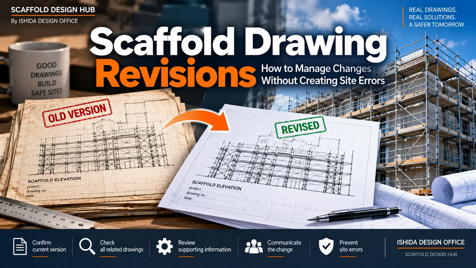
If a local arrangement changes, the designer should consider which other views and documents are affected.
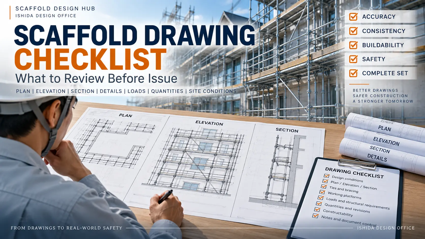
Before issuing a revised local detail, cross-check its location reference, dimensions and component positions against the plan, elevation and section. Where the detail involves a building connection, confirm that the proposed interface is physically achievable using the available project and site information.
This is particularly important when a detail develops later than the main drawing.
The detail may be technically correct while the overall drawing set remains wrong because the change was not propagated to the other views.
This is closely related to the broader pre-issue drawing review process discussed in Scaffold Drawing Checklist: What to Review Before Issue. The central principle there is that plans, elevations, sections and details should not be reviewed as isolated drawings.
A detail is successful only when it clarifies the drawing set without contradicting it.
Requirements Differ Between Countries and Projects
Scaffold documentation should not be treated as globally uniform.
The detail drawings expected on one project may not be the same as those required on another.
Requirements can depend on:
- jurisdiction;
- project specifications;
- scaffold type;
- manufacturer documentation;
- contract requirements;
- complexity of the arrangement;
- site conditions;
- the design and review process.
This is particularly important for an international audience.
A detail commonly expected in one country should not automatically be presented as a universal requirement.
Likewise, there is little value in adding details that a project does not need simply because they appeared in another drawing package.
Before deciding what details to produce, understand what the applicable project actually requires.
Standard Configuration vs Bespoke Design
The distinction between a recognised standard configuration and a bespoke arrangement is useful when thinking about details.
For example, HSE guidance in Great Britain explains that scaffolds assembled outside a generally recognised standard configuration require bespoke calculation by a competent person.
The guidance also identifies project information that should be established during planning, including dimensions, loading, access, sheeting, supporting conditions, building information and restrictions affecting erection, alteration or dismantling.
This does not mean every non-standard-looking drawing condition automatically requires the same response everywhere.
It means the designer must understand which rules, manufacturer instructions, project requirements and engineering requirements apply to that particular scaffold.
DO NOT ASSUME: A detail is a communication tool within the design process. It is not a substitute for the process itself.
Common Scaffold Detail Drawing Mistakes
1. Reusing a Detail Without Checking the New Project
Mistake: Copying a previous detail because the new scaffold looks similar.
Why it matters: Small differences in building geometry, site constraints or project requirements may make the old detail inappropriate.
Better approach: Recheck the actual project conditions before relying on the previous information.
2. Treating a Detail as Proof of Structural Adequacy
Mistake: Assuming that because an arrangement can be drawn, it is structurally acceptable.
Why it matters: Graphic feasibility and structural capacity are not the same.
Better approach: Complete the required structural/design verification separately.
3. Adding Details Without a Clear Purpose
Mistake: Creating numerous details because more information appears more professional.
Why it matters: Each additional representation creates another location that must remain coordinated.
Better approach: Create details where they resolve a genuine communication problem.
4. Allowing Details to Conflict with Main Drawings
Mistake: Updating a detail without updating the associated plan, elevation or section.
Why it matters: The construction team receives conflicting information.
Better approach: Review the drawing set as one coordinated document system.
5. Showing Tie Details Without Checking the Building Interface
Mistake: Designing a neat tie arrangement around the scaffold without adequately considering the actual attachment locations.
Why it matters: The proposed tie may conflict with real building conditions.
Better approach: Check the scaffold and supporting structure together.
6. Assuming Detail Requirements Are Universal
Mistake: Copying the documentation approach used in one jurisdiction or project into every new project.
Why it matters: Applicable requirements and project expectations differ.
Better approach: Confirm the relevant local requirements, project documentation and manufacturer information.
Practical Checklist: Does This Condition Need a Detail?
Before adding another detail to a scaffold drawing, ask:
Communication
- Can the condition already be understood clearly from the plan?
- Can it be understood from the elevation?
- Can it be understood from the section?
- Would someone need to guess how the local condition is intended to work?
- Would an enlarged view materially reduce ambiguity?
Site Interface
- Does the condition interact with an opening, balcony, roof, projection or equipment?
- Is the proposed arrangement compatible with the actual building?
- Are important attachment or support locations physically achievable?
- Is additional site information required before the detail can be completed?
Design
- Does the condition depart from the normal scaffold arrangement?
- Does it require separate structural verification?
- Are the applicable manufacturer instructions and project requirements understood?
- Is specialist engineering input required?
Drawing Coordination
- Is the detail consistent with the plan?
- Is it consistent with the elevation?
- Is it consistent with relevant sections?
- Are dimensions and component positions coordinated?
- If the detail changes, have all affected views been identified?
Necessity
Finally ask:
What problem does this detail solve?
If there is no clear answer, reconsider whether the detail is necessary.
Japanese Practice Note
My scaffold drawing work in Japan began in 1998, and one practical lesson from that experience is that similar buildings should not automatically be treated as identical scaffold projects.
A detail from an earlier drawing may look reusable, but the new building may have different openings, projections, dimensions, access conditions or attachment possibilities.
I therefore consider the actual project conditions more important than the visual similarity of two drawings.
The same principle applies to the amount of information shown. Adding more details does not automatically improve a drawing set. Details are useful when they clarify a condition that cannot be communicated adequately elsewhere; unnecessary repetition can make coordination more difficult.
This is a practical perspective from my work in Japan, not a universal documentation rule.
Scaffold drawing and design requirements differ between countries, projects and scaffold systems. Designers should always check applicable regulations, project specifications, design requirements and manufacturer instructions for the scaffold being used.
FAQ
Does every scaffold drawing need separate detail drawings?
No. A separate detail is useful when an important condition cannot be communicated clearly enough through the main plan, elevation, section or notes. The documentation required also depends on the project, jurisdiction and scaffold system.
What is the difference between a scaffold section and a detail?
A section normally explains the relationship through a cut across the scaffold or building. A detail focuses more closely on a specific local condition that requires additional clarification. In some drawing sets, a detailed section may perform both functions.
Can I reuse a scaffold detail from a previous project?
A previous detail may be a useful reference, but it should not automatically be treated as suitable for another project. Building geometry, site constraints, loads, interfaces, scaffold systems and project requirements can differ.
Does a scaffold detail prove that the design is structurally safe?
No. A drawing communicates the intended arrangement. Structural adequacy must be established through the applicable design process, calculations, system information and requirements.
Why are tie details particularly important?
Because the proposed tie must relate to an actual viable interface with the supporting structure. A tie symbol that appears correct on a drawing may conflict with openings, cladding, balconies, services or other real conditions.
Can too many details make a scaffold drawing worse?
Yes. Repeating the same information across too many views increases the possibility of inconsistencies when one view changes and another does not. Details should have a clear purpose and remain coordinated with the complete drawing set.
Related Topics
Parent / Previous Question: The wider workflow for coordinating plans, elevations, sections, ties, bracing and access.
Next Question: How to verify that the complete drawing set remains coordinated before issue.
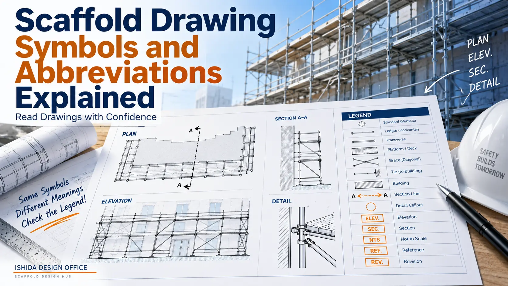
Key Takeaways
- Plan, elevation and section drawings can communicate most scaffold arrangements, but unusual local conditions may require a separate detail.
- A detail should solve a specific communication problem rather than simply add more information.
- A drawing that looks technically convincing does not by itself demonstrate structural adequacy.
- Details from previous projects should not be reused without checking the conditions of the new project.
- Too many details can create contradictions between plans, elevations, sections and local views.
- Tie details require particular care because the proposed attachment must correspond with a viable building interface.
- The details required should reflect the applicable project, jurisdiction, scaffold system and manufacturer information.
Conclusion
A good scaffold drawing is not the drawing with the greatest number of details.
It is the drawing set that communicates the required scaffold arrangement clearly, consistently and with as little ambiguity as reasonably possible.
Use a detail when the standard views cannot adequately explain an important local condition. Then check that the detail agrees with the rest of the drawing set, corresponds with the actual project conditions and receives whatever structural verification the arrangement requires.
The next useful step is to review the complete drawing package—not only the detail in isolation—to confirm that every view still describes the same scaffold.
Official References
Health and Safety Executive (HSE), Great Britain — Scaffolds.
Used for statements concerning recognised standard configurations, bespoke calculation, competent person design, scaffold ties, manufacturer instructions and relevant scaffold design information.
Health and Safety Executive — Scaffolds
Last Verified: September 2026
Regulations, official guidance and manufacturer documentation may change. Always confirm the current requirements applicable to the project location, scaffold system and intended use.
This article is general technical information and is not a substitute for project-specific engineering, applicable law, contract documents, project specifications, manufacturer instructions or competent professional review.
About the Author
ISHIDA DESIGN OFFICE has practical experience in Japan since 1998, specializing in scaffolding design, temporary works planning, CAD drafting, quantity estimation, and construction support.
Drawing on experience from residential, commercial, and industrial projects, he shares practical insights that emphasize not only sound engineering design but also buildability, safety, and real-world jobsite application.
At Scaffold Design Hub, he combines practical experience from Japan with official guidance and technical resources to explain scaffold drawing and design considerations for an international audience.
To learn more about the author and the purpose of this website, visit the About page. For questions or project inquiries, please use the Contact page.
Explore more technical guides on the Scaffold Design Hub homepage.