
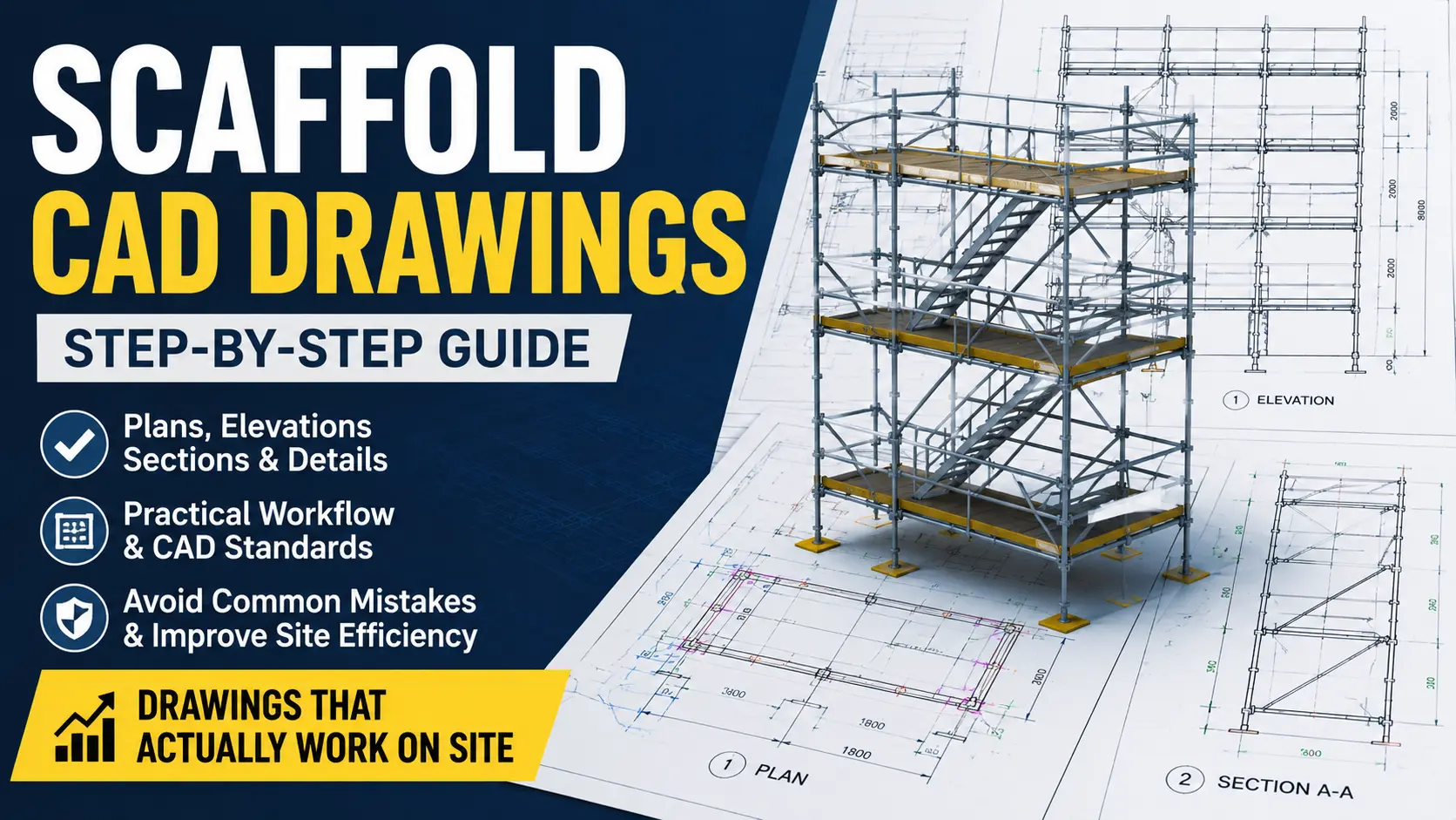
A scaffold CAD drawing does not become useful simply because it looks clean and professional.
Even when the plan and elevation appear consistent, the drawing may still fail on site if the scaffold crew cannot identify the access points, the tie locations are unclear, or potential clashes with canopies, balconies, pipework or other building features are not shown.
Over more than 30 years of working in scaffold planning, CAD drafting, material estimation and temporary works design review, I have learned to focus on three basic requirements:
- The drawing must accurately reflect the actual site conditions.
- The people erecting and using the scaffold must be able to understand it without unnecessary interpretation.
- Changes, reviews and drawing revisions must be clearly traceable.
A good scaffold drawing should not be understandable only to its designer.
The construction supervisor, scaffold contractor, safety officer, estimator and project manager should all be able to look at the same drawing and form a reasonably consistent understanding of what is to be built.
This guide explains a practical workflow for producing scaffold CAD drawings, from reviewing site information and preparing the base drawing to checking revisions and issuing the final PDF.
It does not explain individual AutoCAD commands. Instead, it focuses on the technical decisions and communication principles required to produce scaffold drawings that can be reviewed, estimated and used on site.
- What to confirm before opening your CAD software
- The different purposes of plans, elevations, sections and details
- A practical sequence for producing scaffold drawings
- How to organise CAD layers, blocks and templates
- Common drafting mistakes and how to prevent them
- How drawings connect with material take-offs and work planning
- A practical checklist for reviewing the completed drawing
This guide focuses on practical scaffold CAD workflows rather than software-specific AutoCAD commands.
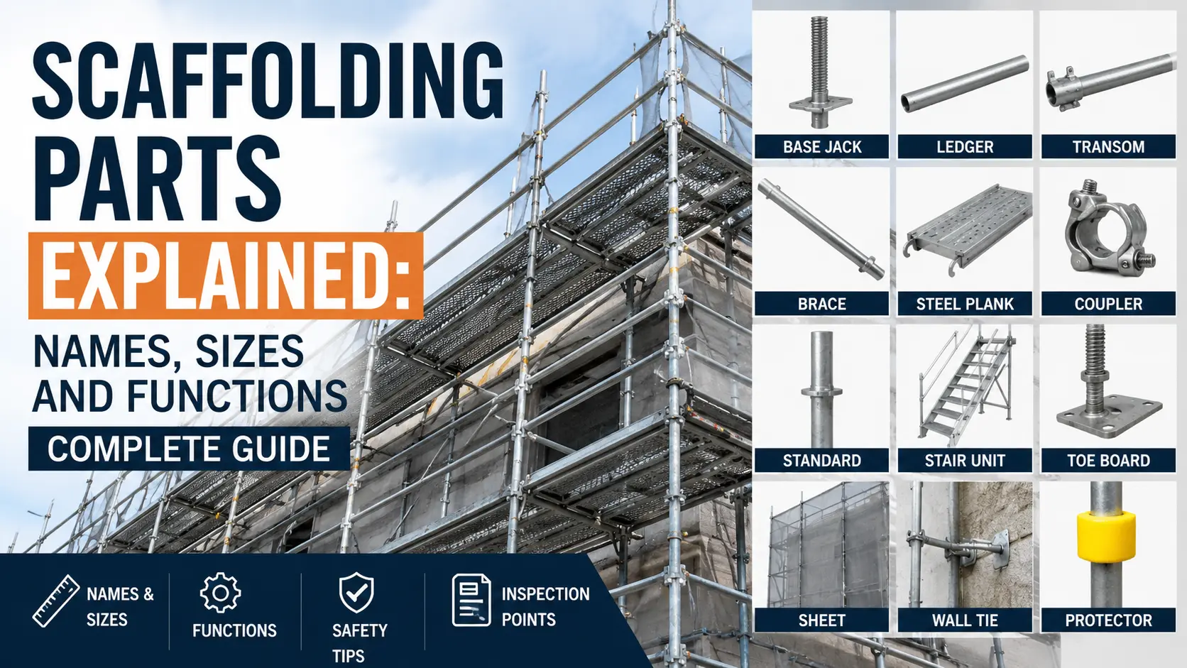
Before learning scaffold CAD drawing techniques, it’s helpful to understand the names and functions of common scaffold components. If you need a refresher, see our complete guide: Scaffolding Parts Explained: Names, Sizes and Functions.
This article explains practical methods for organising and communicating scaffold information through CAD drawings.
Please note:
・This article does not verify the structural adequacy of any scaffold.
・It does not replace local regulations or engineering approval.
・Requirements vary by country, jurisdiction and project.
・Always follow applicable laws, project specifications and the scaffold manufacturer’s current instructions.
Why Scaffold CAD Drawings Matter
The purpose of a scaffold drawing is not simply to show the shape of a scaffold on paper.
A drawing should reduce uncertainty before erection begins.
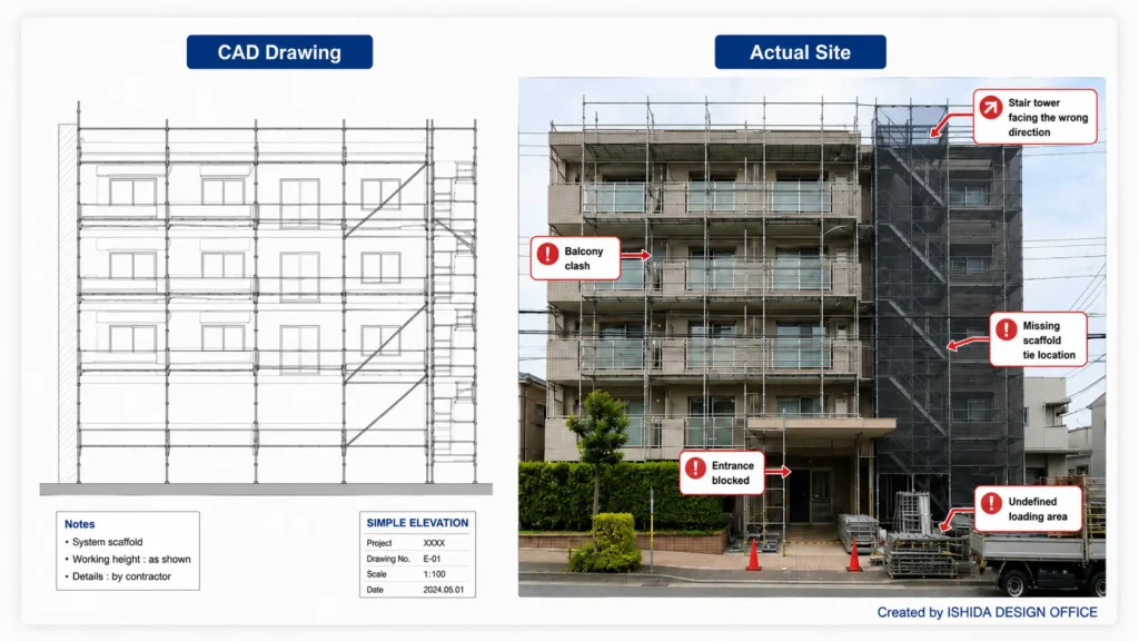
Typical problems include:
- A stair tower facing in the wrong direction
- A scaffold lift or landing clashing with an existing canopy
- A standard positioned in front of an entrance
- Scaffold tie locations that cannot be identified
- Working-platform areas that are not clearly defined
- A loading area conflicting with pedestrian or worker access
- A different number of bays shown on the plan and elevation
- An outdated revision being used for erection
- Material quantities that do not match the latest drawing
These problems are not always caused by poor CAD skills.
They often result from incomplete information, insufficient checking or a failure to show information that exists only in the designer’s mind.
After reviewing scaffold drawings for more than three decades, I have repeatedly found that one missing piece of essential information can cause more difficulty than a visually complex drawing.
For example, a detailed elevation may still be inadequate if there is no plan showing the distance from the building, access locations or the relationship with the site boundary.
At the same time, adding large amounts of text does not automatically improve a drawing. Important information may become difficult to find when it is surrounded by unnecessary notes and background lines.
A good scaffold drawing is not the drawing with the most information.
It is the drawing that places the right information in the right location, at a scale that people can actually read.
What to Check Before Opening CAD
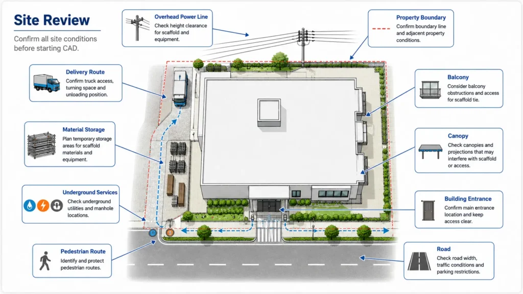
A good scaffold drawing does not begin with a blank CAD file.
It begins with a review of the site conditions, the intended use of the scaffold and the information supplied by the client or project team.
Building Information
At a minimum, confirm the following:
- Overall building dimensions
- Building height
- Floor-to-floor heights
- Balcony and canopy locations
- Roof shape
- Openings and entrances
- Equipment projecting from the facade
- Pipework, ductwork, signs and other obstructions
- The type and reliability of the available architectural drawings
Do not assume that an architectural drawing is completely accurate simply because it has been issued as a CAD file.
On refurbishment projects, the current building may not match the original or as-built drawings. Architectural, structural and building-services drawings may also show different dimensions or levels.
Before drafting, I identify which drawing will be used as the primary reference and list any dimensions or conditions that remain uncertain.
Site and Surrounding Conditions
Confirm:
- The available width for the scaffold
- Property and site boundaries
- The distance to roads
- Pedestrian routes
- Vehicle entrances
- Ground and bearing-surface conditions
- Changes in level, drains and underground structures
- Overhead electrical lines or services
- Material delivery routes
- Crane, hoist or lifting-equipment operating areas
On a restricted site, the scaffold itself is only one part of the planning problem.
You also need to understand where materials will enter the site, where they can be temporarily stored, how workers will access the scaffold and how building occupants or members of the public will move through the area.
Intended Use of the Scaffold
Confirm whether the scaffold is required for:
- Painting
- Facade repairs
- Waterproofing
- Demolition
- Mechanical or electrical work
- Inspection
- Temporary material storage
- Handling heavy materials
- Installing sheeting or debris netting
- Using a hoist or loading platform
The same building may require a different scaffold arrangement depending on the work being carried out.
A scaffold suitable for light painting work may not be suitable for work involving heavy materials or concentrated loads.
Before drafting, establish:
- What work will be performed
- Where it will be performed
- Who will use the scaffold
- What materials and equipment will be placed on it

Questions to Raise Before Drafting
When information is missing, do not hide the uncertainty inside the drawing.
Prepare a list of questions.
For example:
- Will this entrance remain in use during the project?
- What is the confirmed height and projection of this canopy?
- Can the stair tower be used in this location?
- Will sheeting or netting cover the entire scaffold?
- Where will materials be lifted?
- Will materials be temporarily stored on the working platforms?
- Are there areas where scaffold ties cannot be installed?
- Should the drawing follow the architectural information or the verified site condition?
Resolving these questions before detailed drafting usually saves more time than revising a completed drawing later.
A Practical Workflow for Creating Scaffold CAD Drawings
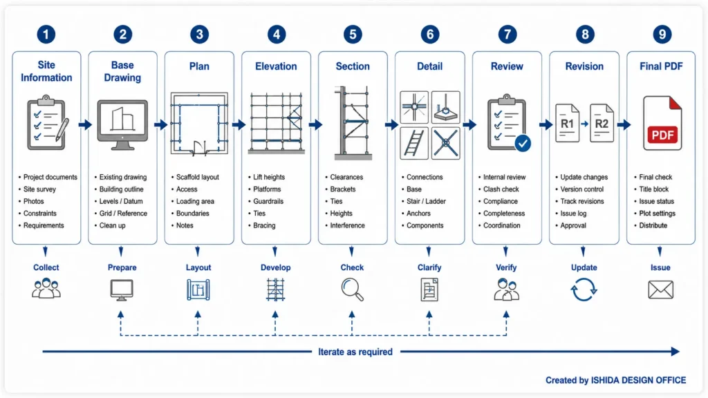
The precise sequence may vary between companies and projects, but a consistent workflow helps prevent omissions and drawing conflicts.
1. Confirm the Purpose and Status of the Drawing
First, establish how the drawing will be used.
It may be prepared for:
- Preliminary estimating
- Construction planning
- Client or principal contractor review
- Structural design review
- Material ordering
- Scaffold erection
- A regulatory or client submission
- Coordination with other temporary works
A preliminary estimating sketch and a drawing issued for construction do not require the same level of detail or checking.
If the intended use is not defined at the beginning, the drawing may require substantial additions or complete reworking later.
The drawing status should also be clear. A preliminary concept should never be mistaken for an approved construction drawing.
2. Prepare the Building Base Drawing
When architectural CAD data is available, retain only the information required for scaffold planning.
This may include:
- External wall lines
- Columns and grid lines
- Canopies
- Balconies
- Entrances
- Stairs
- Services and obstructions
- Roads
- Site and property boundaries
Internal finishes, furniture and unrelated building details can usually be hidden, screened back or placed on separate layers.
Too much architectural information makes the scaffold difficult to read.
However, removing too much information can make it impossible to understand the relationship between the scaffold and the building.
The objective is not to use the architectural drawing exactly as received. The objective is to prepare it as a clear background for scaffold planning.
Where CAD information is unavailable, create a simplified base drawing from verified measurements, survey information or a suitable PDF drawing.
Any unverified information should be identified rather than presented as confirmed fact.
3. Set Units, Scale, Sheet Size and Drawing Standards
Before detailed drafting, establish:
- Drawing units
- Model-space conventions
- Intended plotting scale
- Sheet size
- Text height
- Dimension styles
- Line types and line weights
- Title-block format
- File-naming conventions
- Revision conventions
Do not choose the plotting scale only because it allows the whole building to fit on one sheet.
Check whether key dimensions, scaffold ties, stair locations and notes will remain legible when the drawing is printed or viewed as a PDF.
Where the overall drawing cannot communicate a condition clearly, use a separate section or enlarged detail rather than compressing everything into one crowded view.
4. Develop the Plan First
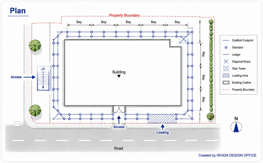
Elevations are visually prominent on facade-scaffold drawings, but the plan is usually the foundation of the layout.
The plan should help establish:
- The overall scaffold footprint
- The distance between the scaffold and the building
- Standard locations
- Bay arrangement
- Corner arrangements
- Entrances
- Stair towers and ladder access
- Loading locations
- Canopies and balconies
- Site obstructions
- Roads and adjacent properties
- Bracketed or cantilevered areas
- Restricted-access zones
The aim is not simply to divide the facade into equal bays.
The arrangement must respond to entrances, changes in building line, balconies, canopies, stairs, services and other site restrictions.
Avoid placing all dimensional adjustment into the final bay unless there is a clear technical reason to do so. Consider the complete elevation and decide where non-standard bay lengths can be accommodated most effectively.
5. Produce the Elevations
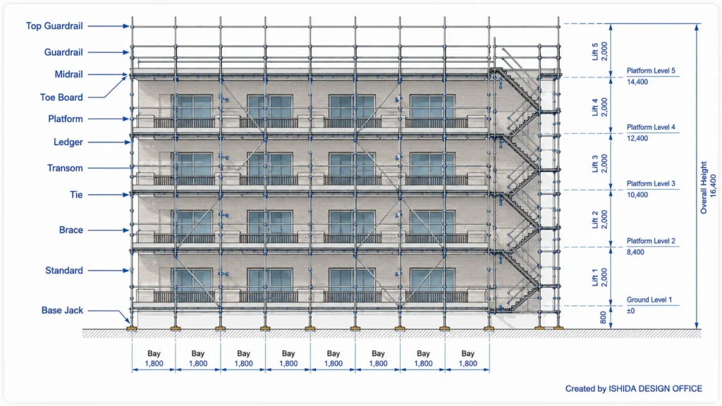
Once the standard positions and bay arrangement are established in plan, develop the principal elevations.
An elevation may need to show:
- Overall scaffold height
- Lift heights
- Bay arrangement
- Working platforms
- Top guardrails
- Midrails or intermediate guardrails
- Toe boards or other edge protection
- Diagonal bracing
- Scaffold ties
- Access systems
- Hoists or loading arrangements
- Protective fans or loading-bay protection
- Sheeting or netting extents
- Special strengthening
- Relevant building features
An elevation is not simply a picture of the outside of the scaffold.
It is used to check the vertical arrangement, platform levels, ties, bracing, access and the relationship between the scaffold and the building.
Compare the scaffold lifts with floor levels, work areas, windows, balconies and roof lines.
Where the arrangement changes along the elevation, show the change clearly rather than relying on a general note.
6. Add Sections Where Plans and Elevations Are Not Enough
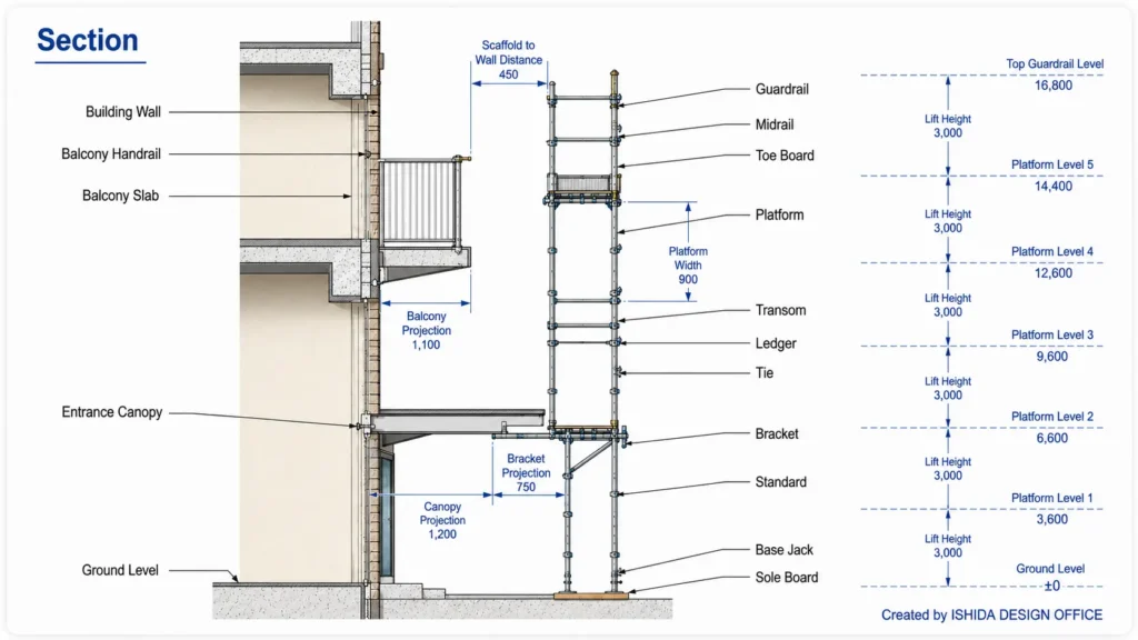
Use sections wherever the relationship between the scaffold and the building cannot be understood clearly from the main views.
Sections are particularly useful at:
- Canopies
- Balconies
- Bracket scaffolds
- Cantilevered areas
- Bridged openings
- Locations where the scaffold-to-facade distance changes
- Roadside protective arrangements
- Roof edges
- Sloping or stepped ground
- Stair-tower connections
- Loading bays
- Pedestrian or vehicle access routes
A condition may be obvious to the designer but unclear to a supervisor or scaffolder who sees only the issued drawing.
From more than 30 years of preparing and checking scaffold drawings, one principle has remained especially valuable:
Where a condition could reasonably be misunderstood, show it in section rather than relying only on a note.
7. Provide Details for Non-Standard Areas
Separate standard arrangements from areas that require specific consideration.
Details may be required for:
- Non-standard ties
- Bridging over openings
- Lattice or bridging beams
- Brackets
- Cantilevered sections
- Roof-level scaffolds
- Suspended scaffolds
- Loading platforms
- Connections to stair towers
- Sheeting or netting terminations
- Areas where ties cannot be installed
- Interfaces between different scaffold systems
Keeping a drawing simple does not mean removing information needed for safe execution.
Where scaffolders would otherwise need to make an important technical decision on site, provide a clear detail, reference an approved standard configuration, or identify the requirement for further design.
8. Add Dimensions, Symbols and Notes
More dimensions do not always make a drawing better.
Prioritise dimensions needed for setting out, erection and checking, including:
- Overall dimensions
- Bay lengths
- Scaffold width
- Distance from the facade
- Overall scaffold height
- Lift heights
- Canopy and opening levels
- Stair-tower positions
- Cantilever dimensions
- Locations of non-standard areas
Avoid repeating the same dimension in several places unless there is a clear reason.
Repeated dimensions can become inconsistent after revisions.
Establish primary dimensions and use detail references where appropriate.
Do not use excessive company-specific abbreviations without explanation. Where project-specific symbols are used, include a legend.
Notes should supplement the graphics, not replace them.
“Install as required” is rarely adequate for a condition that affects stability, access or structural performance.
9. Complete the Title Block and Revision Record
The title block should normally identify:
- Project name
- Drawing title
- Drawing number
- Scale
- Date
- Drawn by
- Checked by
- Revision number
- Revision date
- Revision description
- Drawing status
Depending on the company or project system, drawing status may include:
- Preliminary
- For Review
- For Approval
- For Construction
- As Built
- Superseded
Unapproved and construction-status drawings should not look identical.
When revising a drawing, check more than the area that has changed.
Also confirm:
- Drawing numbers
- Revision codes
- Dates
- Detail references
- Related drawings
- Material schedules
- Calculation references
- Method statements
- PDF sheet sets
Revision control is not simply an administrative requirement. It is part of communicating correct technical and safety information to the site team.
10. Review the PDF After Export
A drawing that looks clear in CAD may become difficult to read after export or printing.
Check the final PDF for:
- Legibility at the intended paper size
- Appropriate text size
- Clear distinction between building and scaffold lines
- Overlapping dimensions
- Visible ties and bracing
- Correct detail references
- Consistent revision information
- Unwanted layers
- Correct sheet order
- Legibility when printed in black and white
Where possible, ask someone other than the original drafter to review the final drawing.
The person who created a drawing already understands its intended meaning and may unconsciously fill in information that is not actually shown.
An independent reviewer is more likely to identify missing dimensions, unclear access arrangements and conflicting views.
Japanese Practice Note
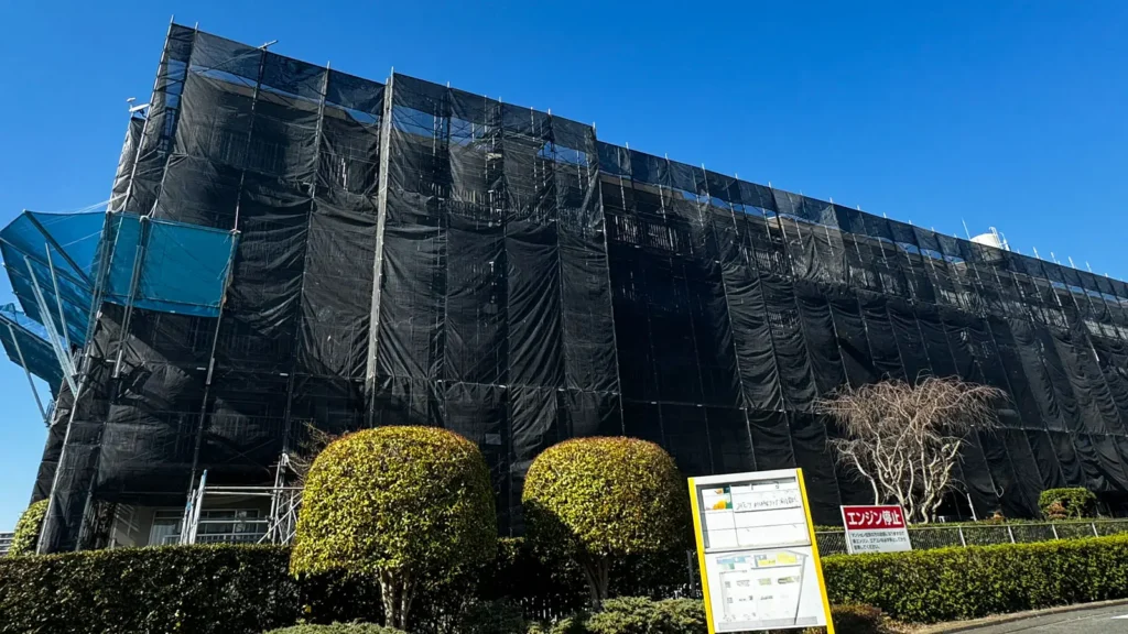
In many Japanese renovation projects, scaffold planning is strongly influenced by limited working space. The scaffold may need to fit between the building and a narrow road, an adjacent property, overhead services, entrances, balconies or pedestrian routes.
Under these conditions, a standard elevation alone is often not enough.
In more than 30 years of temporary works drafting and scaffold estimation, I have found that many of the most important decisions must be made before detailed CAD work begins.
The team should discuss:
- Access routes
- Material-delivery paths
- Stair-tower locations
- Projecting brackets
- Protective sheeting
- Loading areas
- Interfaces with pedestrians and building users
A minor conflict that appears manageable on a drawing can create a significant delay after the scaffold materials arrive.
For this reason, scaffold drawings for restricted Japanese sites often rely on additional plans, sections, enlarged details and clearly defined zones.
The same principle can be applied outside Japan:
Show where the scaffold changes, where people enter or pass close to it, and where the standard arrangement no longer applies.
Requirements vary by country, jurisdiction and project. Always follow applicable local laws, project specifications, risk assessments and the scaffold manufacturer’s instructions.
Want to understand the thinking behind these recommendations?
Read my experience after more than 30 years of scaffold design and temporary works drafting.

Organising CAD Layers, Blocks and Templates
A consistent CAD system prevents the drafter from rebuilding the same setup for every project.
However, the purpose of a template is not to copy an old project without review.
It is to separate reusable drafting resources from technical conditions that must be reconsidered for each site.
Example Layer Structure
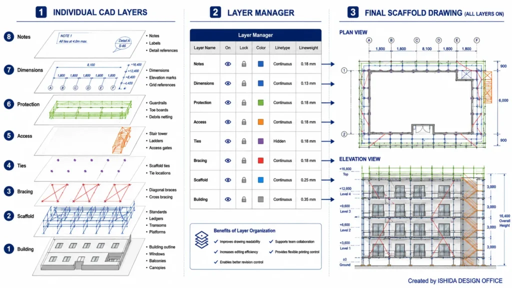
The following is an example naming system, not an international standard:
- SCAFF-GRID — Grid and reference lines
- SCAFF-PLAN — Scaffold components shown in plan
- SCAFF-ELEV — Scaffold components shown in elevation
- SCAFF-PLATFORM — Working platforms
- SCAFF-GUARD — Guardrails, midrails and toe boards
- SCAFF-TIE — Ties and anchors
- SCAFF-BRACE — Bracing and strengthening
- SCAFF-ACCESS — Stairs, ladders and access systems
- SCAFF-PROTECTION — Sheeting, netting and protective fans
- SCAFF-DIM — Dimensions
- SCAFF-TEXT — Notes and legends
- BUILDING-BASE — Architectural background
- REVISION — Revision clouds and revision symbols
The exact layer names are less important than consistent company-wide use.
A person receiving the CAD file should be able to display or hide the scaffold structure, ties, access, protection and building background without having to investigate an inconsistent layer system.
Reusable Blocks
Reusable blocks may include:
- Title blocks
- North arrows
- Section markers
- Detail-reference markers
- Scaffold-tie symbols
- Stair towers
- Standard edge-protection sections
- Standard scaffold modules
- Revision symbols
- General-note frames
Blocks can improve drafting efficiency, but inserting a block does not complete the design.
The following must still be reviewed for the individual project:
- Dimensions
- Loads
- Connection conditions
- Scaffold system
- Tie arrangement
- Ground and support conditions
- Sheeting or netting
- Manufacturer requirements
Layher provides official technical documentation that includes approvals, structural information, technical brochures, and assembly and use instructions. PERI also provides information on scaffold systems and digital planning tools. Any CAD library, manufacturer block or planning template should be checked against the current documentation for the system actually being used.
Connecting the Drawing to Material Take-Off and Work Planning
What the Drawing Supports
A scaffold CAD drawing is not only a visual representation.
When properly organised, it can provide the basis for:
- Material take-off
- Preliminary weight calculations
- Transport planning
- Labour planning
- Rental-period planning
- Erection sequencing
- Risk assessment
- Method statements
- Safe Work Method Statements
- Inspection planning
What to Include in the Material Take-Off
When the plans and elevations are consistent, they can help identify approximate quantities for:
- Standards or vertical posts
- Ledgers and horizontal members
- Working platforms
- Bracing
- Scaffold ties
- Stairs and ladders
- Sheeting and netting
- Special components
However, accurate quantities cannot normally be calculated using only:
number of bays × number of lifts
The take-off must also account for:
- Corners
- Ends
- Stair towers
- Cantilevered sections
- Openings
- Lattice beams
- Loading bays
- Changes in building shape
- Non-standard lift or bay arrangements
- Special tie conditions
Review Quantities After Every Drawing Revision
Through many years of scaffold estimation, I have learned not to treat the drawing and material schedule as unrelated documents.
When the drawing changes, review the effect on:
- Material quantities
- Total or estimated weight
- Transport requirements
- Labour
- Programme
- Special components
- Structural calculations
- Method statements
If the drawing is revised but the material schedule remains unchanged, the result may be missing materials, excess materials or incorrect transport and labour planning.
Attribute-enabled blocks and CAD data extraction can support the process, but automated quantities should still be reviewed by someone who understands the scaffold arrangement.
Automation can count what has been drawn. It cannot always identify what has been drawn incorrectly or omitted.

Scaffold Drawings and International Safety Principles
Scaffold legislation, competence requirements, inspection systems and design responsibilities vary between countries and jurisdictions.
However, official guidance commonly emphasises several broad principles:
- Plan the work properly
- Identify hazards and constraints
- Involve appropriately competent people
- Inspect and maintain the scaffold
- Review arrangements that fall outside standard configurations
- Follow the scaffold manufacturer’s instructions
- Communicate changes to affected people
- Keep construction information consistent and traceable
United States: OSHA
OSHA’s construction scaffold requirements are contained in 29 CFR 1926 Subpart L.
Under OSHA, defined responsibilities can differ between a competent person, a qualified person and, for certain scaffold designs, a registered professional engineer.
For example, OSHA requires scaffolds and scaffold components to be inspected for visible defects by a competent person before each work shift and after an occurrence that could affect structural integrity. OSHA also specifies training requirements for employees working on scaffolds.
The drawing and project procedures should therefore make clear which decisions, inspections and approvals are required and who is responsible for them.
Do not use the terms “competent person,” “qualified person” and “engineer” as though they mean the same thing.
United Kingdom: HSE
HSE states that scaffolds should be designed, erected, altered and dismantled only by competent people, with the work carried out under the direction of a competent supervisor.
HSE also explains that scaffold inspection must be performed by a competent person whose knowledge, training and experience are appropriate for the type and complexity of scaffold being inspected.
In practical drawing terms, the design information should make the intended configuration clear enough to be erected, reviewed and inspected against that information.
Australia: Safe Work Australia
Safe Work Australia provides guidance on managing risks associated with scaffolds and scaffolding work.
Its guidance covers planning, inspection, maintenance and the management of risks associated with different scaffold types.
Australian legal requirements may differ between states and territories because model WHS laws are implemented and enforced through the relevant jurisdictions.
Always confirm the applicable requirements with the appropriate state or territory regulator.
Japan: Ministry of Health, Labour and Welfare
Japan’s Ministry of Health, Labour and Welfare has strengthened measures intended to prevent falls from scaffolds.
Amendments introduced from October 2023, with some provisions taking effect in April 2024, addressed matters including the permitted use of single-row scaffolds, the appointment of scaffold inspectors, and the recording and retention of inspectors’ names following certain inspections.
Japanese projects should be reviewed against the current Industrial Safety and Health Regulations, official notices, project requirements and manufacturer instructions.
United Kingdom Industry Guidance: NASC
NASC provides TG20 guidance for tube-and-fitting scaffolding and TG30 guidance for system scaffolding through its ePortal.
These resources help users distinguish between recognised standard configurations and arrangements requiring additional design consideration. They are UK industry resources and should not be treated as worldwide legal standards.
A note copied from a drawing used in one country should not automatically be reused on a project in another.
Requirements vary by country, jurisdiction and project. Always follow local laws, project specifications, risk assessments, engineering requirements and the scaffold manufacturer’s instructions.
10 Common Scaffold CAD Drawing Mistakes
1. Starting the Drawing Before Confirming Site Conditions
Opening CAD immediately may make the project feel as though it is progressing.
However, if the entrance arrangements, canopy dimensions, ground conditions or delivery route are confirmed later, the entire scaffold layout may need to be revised.
List the missing information before detailed drafting begins.
2. Treating the Architectural Drawing as Automatically Correct
Existing buildings do not always match their drawings.
Confirm critical dimensions through:
- Site surveys
- Photographs
- Measurements
- Coordination drawings
- Questions to the project team
Where a dimension has not been verified, do not present it as though it has been confirmed.
3. Planning Only in Elevation
An elevation cannot fully show:
- The distance from the building
- Entrances
- Boundaries
- Roads
- Canopy projections
- Pedestrian routes
- Changes in facade line
For most facade scaffolds, provide at least a plan and the necessary elevations.
4. Writing “Ties as Required”
Scaffold ties affect stability and should not be left as an undefined site decision.
Show or reference:
- The intended tie arrangement
- Tie type
- Special tie conditions
- Relevant calculation or design reference
- Manufacturer requirements
Specific tie spacing and capacity depend on factors including local regulations, scaffold configuration, loading, sheeting, wind exposure, tie type and manufacturer information.
5. Showing Access Without Showing the Complete Route
A stair tower symbol is not enough if the drawing does not show:
- The ground-level entrance
- Stair direction
- Landing orientation
- Connections to working platforms
- Restricted areas
- Access around loading bays
Follow the worker’s route from ground level to the intended working area.
6. Reusing Standard Details Without Reviewing the Site
Standard details are useful, but they are not automatically suitable for every project.
Review:
- Anchor substrate
- Building form
- Loads
- Scaffold system
- Tie forces
- Connections
- Sheeting
- Ground support
A copied detail may look correct while being unsuitable for the new conditions.
7. Allowing the Plan, Elevation and Section to Conflict
A plan showing ten bays and an elevation showing eleven bays can affect both erection and estimation.
Cross-check:
- Bay numbers
- Overall dimensions
- Stair positions
- Loading areas
- Tie zones
- Special details
Drawing coordination should be a defined review step rather than an informal final glance.
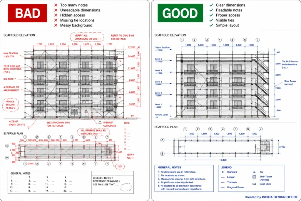
8. Overloading the Drawing with Text and Dimensions
Too much information can hide the most important information.
Improve clarity by:
- Removing unnecessary background lines
- Moving complex information to details
- Using consistent note locations
- Creating legends
- Separating general notes from project-specific instructions
9. Failing to Explain Revisions
Changing only the revision number forces the reviewer to compare every part of the drawing.
Use:
- Revision clouds
- Revision descriptions
- Dates
- Updated status information
- Clear superseded-drawing controls
10. Failing to Check the PDF and Printed Output
Fine lines may disappear and small text may become unreadable after export.
Review the drawing at the actual issue size, including a black-and-white print test where relevant.
Practical Scaffold CAD Drawing Checklist
Before Drafting
- Have the latest available building drawings been received?
- Have differences between the drawings and site conditions been identified?
- Is the intended use of the scaffold clear?
- Is the work area defined?
- Are the intended loads and work activities understood?
- Have boundaries, roads and pedestrian routes been reviewed?
- Have canopies, services, pipework and electrical lines been checked?
- Are delivery and temporary storage areas understood?
- Has the access-system location been discussed?
- Have missing items been listed as formal questions?
Plan Review
- Is the full scaffold footprint shown?
- Is the distance from the building clear?
- Are standards and bay arrangements identifiable?
- Are entrances kept clear or specifically addressed?
- Do corner arrangements work?
- Are stairs and ladders located clearly?
- Are loading areas shown?
- Are roads, adjacent properties and obstructions shown?
- Are non-standard areas referenced to details?
Elevation and Section Review
- Is the overall scaffold height shown?
- Are lift heights clear?
- Are working-platform levels shown?
- Is the required edge protection represented?
- Are ties shown or clearly referenced?
- Are bracing and strengthening shown?
- Are stair-tower connections clear?
- Have canopy and balcony clashes been checked?
- Are sections or details provided for non-standard areas?
Drawing-Control Review
- Is the project name correct?
- Is the drawing title correct?
- Is the drawing number correct?
- Is the scale correct?
- Are the issue date and revision date correct?
- Are the drafter and checker identified?
- Is the revision description complete?
- Can the drawing be distinguished from superseded versions?
- Are related drawing references correct?
- Is the PDF sheet order correct?
Final Technical Review
- Does the plan agree with the elevation?
- Does the elevation agree with the sections?
- Does the drawing agree with the material schedule?
- Does the drawing agree with the calculation assumptions?
- Does the drawing agree with the method statement?
- Have the latest manufacturer instructions been reviewed?
- Have local laws and project specifications been checked?
- Is the drawing legible at the intended issue size?
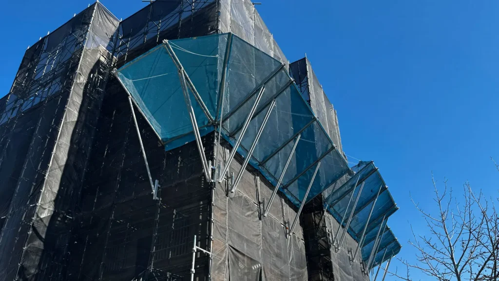
Example Scenario: A Stair Tower Clashes with an Existing Canopy
The following is an illustrative scenario, not a description of a specific project.
The Problem
A stair tower is positioned at the front of a building.
When the elevation is developed, an intermediate landing is found to clash with an existing entrance canopy.
The Cause
The canopy projection was shown on the plan, but its level was not confirmed.
The stair tower was positioned according to the available plan space without checking the vertical relationship between:
- The canopy
- The stair flights
- The landings
- The working-platform connections
The Drawing Response
- Confirm the canopy height and projection.
- Produce a plan, elevation and section through the stair tower.
- Check the direction of the stair flights and landings.
- Confirm the connection to each required working platform.
- Move or reorient the stair tower if necessary.
- Review the revised worker access and material-delivery routes.
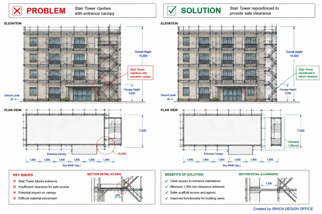
Expected Benefit
Identifying the clash before erection may avoid dismantling and rebuilding part of the stair tower, changing the arrangement during erection, or ordering additional components at short notice.
Prevention
Make section checks a standard part of the drawing workflow for areas involving both plan and vertical constraints, including:
- Stair towers
- Loading platforms
- Canopies
- Balconies
- Bridged access routes
Related Topics
A clear scaffold drawing is only one part of effective scaffold planning.
For component terminology and functions, read Scaffolding Parts Explained: Names, Sizes and Functions.
For material quantities, see How to Estimate Scaffolding Materials from Drawings.
For stability and tie planning, read Scaffold Tie Patterns and Why They Matter.
For post-erection checks, see Scaffold Inspection Checklist for Site Supervisors.
For non-standard structures, read When Does a Scaffold Require Structural Design?
Key Takeaways
- A good scaffold drawing begins with verified site information, not with CAD.
- Plans, elevations, sections and details serve different purposes.
- Access, ties, bracing, platforms and non-standard areas should not be left ambiguous.
- When a drawing changes, the material schedule, calculations and work-planning documents should also be reviewed.
- Revision control is part of communicating correct technical and safety information to the site.
Conclusion
The quality of a scaffold CAD drawing is not determined only by how quickly the lines were produced.
It depends on whether the drafter understands the site conditions, identifies where people may misunderstand the arrangement, and uses plans, elevations, sections and details appropriately.
After more than 30 years of working with scaffold drawings and material estimates, I have repeatedly seen that a small question raised before drafting can prevent a much larger problem later.
Do not make “finishing the drawing” the primary objective.
The objective is to produce information that can be understood, checked and used correctly on site.
Before issuing your next drawing, ask one question:
Could someone seeing this drawing for the first time understand the intended scaffold without having to guess?
That question alone can significantly improve the quality of a scaffold drawing.
The author and publisher accept no responsibility for decisions, designs, construction methods or site activities based solely on this article. Project-specific engineering judgement, risk assessment and compliance with applicable regulations remain the responsibility of the relevant parties.
This article is provided for general educational and informational purposes only and should not be relied upon as project-specific engineering, legal or safety advice.
Official References
- OSHA — 1926 Subpart L: Scaffolds
https://www.osha.gov/laws-regs/regulations/standardnumber/1926/1926SubpartL - OSHA — 1926.451: General Requirements
https://www.osha.gov/laws-regs/regulations/standardnumber/1926/1926.451 - OSHA — 1926.454: Training Requirements
https://www.osha.gov/laws-regs/regulations/standardnumber/1926/1926.454 - HSE — Scaffolds
https://www.hse.gov.uk/construction/safetytopics/scaffoldinginfo.htm - HSE — Scaffolding Frequently Asked Questions
https://www.hse.gov.uk/construction/faq-scaffold.htm - HSE — Construction Work at Height Frequently Asked Questions
https://www.hse.gov.uk/construction/faq-height.htm - Safe Work Australia — Scaffolding
https://www.safeworkaustralia.gov.au/safety-topic/hazards/scaffolding - Safe Work Australia — Scaffolds and Scaffolding Work General Guide
https://www.safeworkaustralia.gov.au/doc/scaffolds-and-scaffolding-work-general-guide - Ministry of Health, Labour and Welfare, Japan — Strengthened Measures to Prevent Falls from Scaffolds
https://www.mhlw.go.jp/stf/newpage_40439.html - Ministry of Health, Labour and Welfare, Japan — Workplace Safety Site: Scaffolds
https://anzeninfo.mhlw.go.jp/yougo/yougo56_1.html - Layher — Official Downloads and Technical Documentation
https://www.layher.com/en-de/services/downloads - PERI — Official Scaffolding Systems
https://www.peri.com/en/competences/scaffolding-systems.html - NASC — TG20 and TG30 Guidance
https://nasc.org.uk/nasc-eportal.html
Last Verified: July 2026
All external references and official guidance were checked for accessibility at the time of writing.
Readers should confirm the latest requirements through the relevant authorities, local regulators, project specifications and the current documentation issued by the scaffold manufacturer.
About the Author
Kenzo Ishida is the founder of ISHIDA DESIGN OFFICE. With more than 30 years of practical experience in Japan, he has specialized in scaffolding design, temporary works planning, CAD drafting, quantity estimation, and construction support.
Drawing on experience from residential, commercial, and industrial projects, he shares practical insights that emphasize not only sound engineering design but also buildability, safety, and real-world jobsite application.
At Scaffold Design Hub, he combines practical experience from Japan with official guidance and technical resources from government agencies, manufacturers, and industry organizations around the world to provide reliable, practical information for construction professionals.
To learn more, visit the About page. For questions or project inquiries, please use the Contact page.