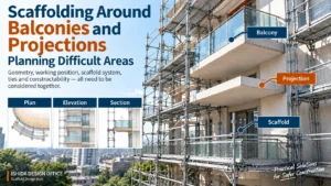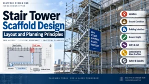

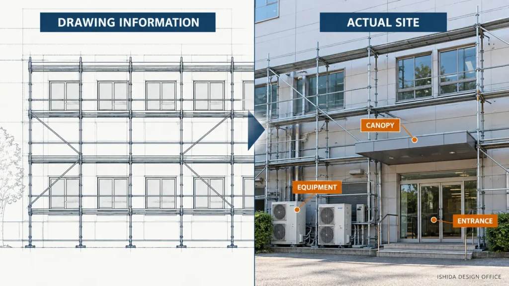
A scaffold can fit perfectly around the building shown on a drawing and still fail to fit the building that actually exists.
Entrances may be in inconvenient positions. Canopies may have been added after the original building drawings were produced. Outdoor equipment may occupy the space intended for standards. A façade may project farther than expected, or a required pedestrian route may force an opening through a previously regular scaffold layout.
These are not simply drafting inconveniences. They can affect scaffold geometry, working platforms, ties, bracing, access and, in some cases, the structural assumptions behind the arrangement.
Design the scaffold around the building and site that actually exist—not only around the information shown on the first drawing you receive.
HSE guidance similarly identifies relevant building dimensions and drawings, ground or supporting conditions, pedestrian walkways, restrictions on tie locations and restrictions affecting erection or alteration as information that may need to be specified when scaffolding is planned.
Health and Safety Executive — Scaffolds
Why Openings and Obstructions Matter in Scaffold Planning
Scaffold planning is a coordination problem as much as a dimensional one.
A designer may begin with the building perimeter, scaffold width, bay arrangement and lift levels. But the resulting geometry must coexist with everything already occupying the same space.
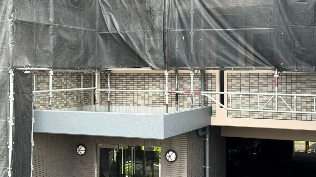
An opening can interrupt a standard. A canopy can interfere with the inner line of the scaffold. Equipment can occupy the intended base position. A building projection can reduce the working clearance at higher levels.
The effect is often connected: changing one part of the arrangement may affect several others.
This is why openings and obstructions should be identified before the scaffold layout becomes too developed, rather than treated as minor corrections at the end.
What Counts as an Opening or Obstruction?
For scaffold planning purposes, an obstruction is not limited to a physical object blocking a standard.
It is useful to think about four groups.
Openings
Typical examples include:
- building entrances;
- loading or service doors;
- garage openings;
- large façade openings; and
- routes that must remain open through the scaffold.
The important question is not simply whether an opening exists. It is whether its position and required clear dimensions are compatible with the proposed scaffold arrangement.
Building Projections
These may include:
- canopies;
- balconies;
- bay windows;
- roofs and eaves;
- façade projections;
- architectural features; and
- changes in the building line.
A projection can be easy to miss when planning primarily from a plan drawing.
Services and Equipment
Potential conflicts include:
- outdoor HVAC units;
- pipes;
- ducts;
- signs;
- cable routes;
- fixed plant; and
- equipment added after the building was originally constructed.
These are particularly important in renovation work because the current building may no longer match the original drawings.
Site and Access Constraints
Some of the most important “obstructions” are not parts of the building at all.
Pedestrian routes, vehicle access, material delivery routes, property constraints and available erection space can all limit where a scaffold can actually be placed.
HSE construction-planning guidance recommends gathering site information before work begins and considering features such as ground conditions, access, public routes, nearby roads and other activities around the site.
HSE — Planning for Construction Work
Start With the Building That Actually Exists
One of the most useful habits in practical scaffold planning is to distinguish between design information and existing conditions.
They should agree—but they do not always.
Use the Latest Available Drawings
An old architectural drawing can still look completely credible.
That is precisely why using an outdated drawing can be dangerous from a planning perspective. Changes to the façade, external wall build-up, openings or equipment may not be visible until later.
In my design work, I have encountered situations where earlier drawing information was used even though the actual building condition had changed. In one case, changes in the external ALC wall condition affected where scaffold ties could be planned.
The lesson is not that drawings are unreliable. The lesson is that drawing revision status matters.
Before developing the scaffold arrangement, confirm that the information being used is the latest available project information.
Compare Drawings With Current Site Photographs
Photographs can reveal information that architectural drawings do not.
In practice, I have found existing structures, outdoor equipment and later additions that were not represented on the design information initially available for scaffold planning.
This makes current site photography particularly valuable for renovation projects.
Useful photographs should not simply show the front of the building. They should help answer specific planning questions:
- What occupies the ground around the façade?
- Are there projections at higher levels?
- Is external equipment installed?
- Are entrances and access routes still in the positions shown?
- Has part of the building been extended or modified?
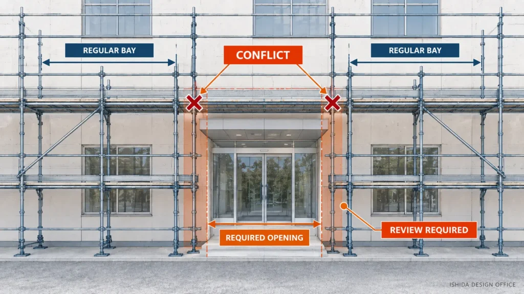
Check Openings Before Fixing the Bay Layout
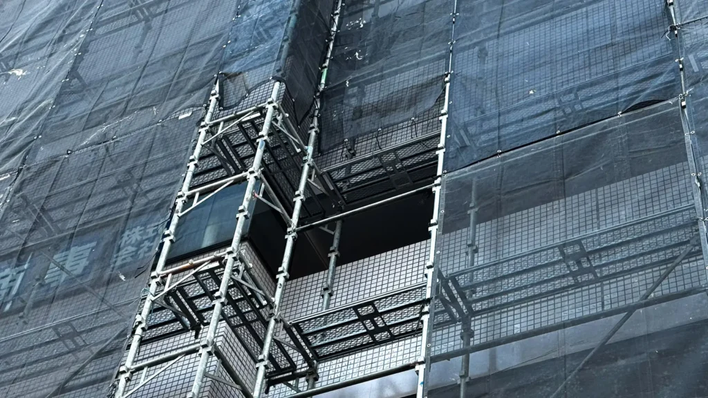
An opening required by the building or site does not automatically fall in a convenient position relative to the scaffold bays.
I have had to reconsider an initial scaffold plan because the required opening did not align appropriately with the proposed scaffold arrangement.
This is why entrance and opening requirements should be identified early.
The designer should establish:
- where the opening is required;
- what function it serves;
- whether people, vehicles or materials must pass through it;
- what clear space needs to remain available;
- which scaffold components may be affected; and
- whether the opening creates a condition requiring additional design review.
DO NOT ASSUME: An opening can simply be “added later.” A change that looks small on a drawing can have wider consequences.
Look Beyond the Plan View
Many scaffold conflicts are three-dimensional.
A plan drawing may suggest adequate clearance while the elevation or section reveals a completely different condition.
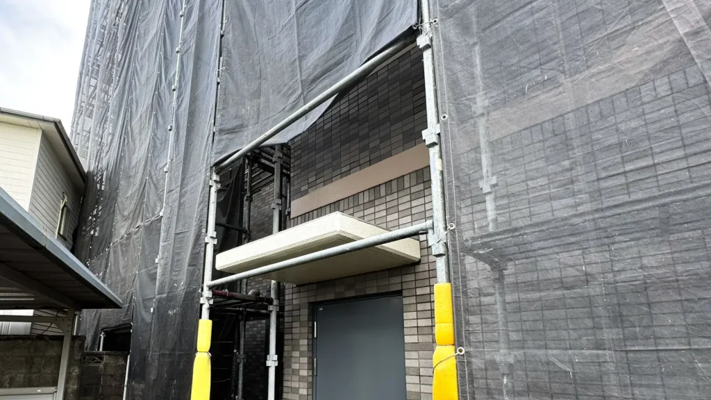
Canopies and Projections
I have planned scaffolding from design drawings and later found that a canopy had been added to the actual building.
External additions of this kind can occupy precisely the space that appeared available on the drawing.
The same issue can occur with equipment such as outdoor air-conditioning units, which are often added during the life of a building.
Bay Windows and Façade Changes
The actual projection of a building element can also differ from what was expected from the design information.
In one project, a bay window projected substantially farther outward than indicated by the building design information because of the way the final construction had been resolved. The scaffold plan therefore had to be reconsidered.
Critical façade projections should be checked in three dimensions and, where necessary, against current site information.
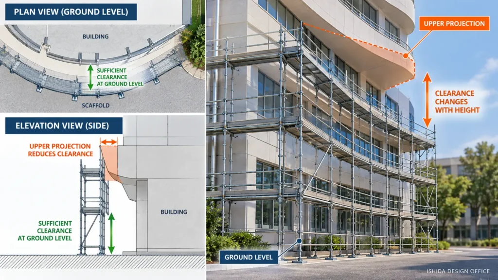
Curved and Outward-Projecting Buildings
Irregular geometry deserves particular attention.
A curved building cannot always be treated as a sequence of simple straight elevations. Similarly, a building that projects progressively outward at higher levels may have sufficient clearance near ground level but inadequate clearance above.
Plan, elevation and section therefore need to tell the same geometric story.
Check Existing Services and Equipment
Mechanical and electrical equipment can turn apparently available space into unusable space.
Outdoor HVAC units are a common example in existing buildings. Pipes, ducts, signs and other services can have the same effect.
The important distinction is between known obstacles and assumed clear space.
If the available information does not establish that an area is clear, the designer should be cautious about treating it as clear.
Where current site information is incomplete, additional photographs, measurements or project information may be necessary before finalising the affected area.
This principle is consistent with broader temporary-works guidance: assumptions behind standard solutions need to remain valid for the actual site conditions.

Do Not Treat Tie Locations as Empty Points on a Drawing
Tie planning illustrates particularly well why the building interface matters.
A regular pattern drawn on an elevation does not prove that every proposed tie can actually connect to a suitable part of the building.
In my work, where ties needed to connect to structural steel, the actual position of that steel had to be understood accurately. Openings, façade construction and changes to the external wall can all influence available tie positions.
Therefore, tie coordination should consider both sides of the interface:
- Scaffold side: where the tie is required in relation to the scaffold arrangement.
- Building side: whether a suitable and permitted connection location actually exists there.
The detailed design, type, spacing and connection requirements depend on the scaffold system, building, project requirements, applicable rules and other design conditions and should be verified accordingly.
For a dedicated explanation of this subject, see Scaffold Ties Explained: Types, Spacing & Layout.
Access Routes Can Change the Scaffold
A scaffold is rarely the only thing using the space around a building.
People may still need to enter the building. Vehicles may need access. Materials may need to be delivered. Contractors may need to pass through particular areas.
These requirements can also change after initial planning.
I have experienced a project where the required circulation arrangement was changed after the initial scaffold planning. Additional access had to be maintained, resulting in an additional scaffold opening and a significant revision to the original arrangement.
Importantly, an added opening should not automatically be treated as a drafting change.
If it changes the structural arrangement, the affected scaffold needs appropriate structural review and, where required, calculation.
HSE specifically identifies pedestrian walkways and restrictions affecting erection, alteration or dismantling among the information that may need to be considered when scaffolding is specified. Its public-protection guidance also emphasises planning the relationship between pedestrians and vehicle movements.
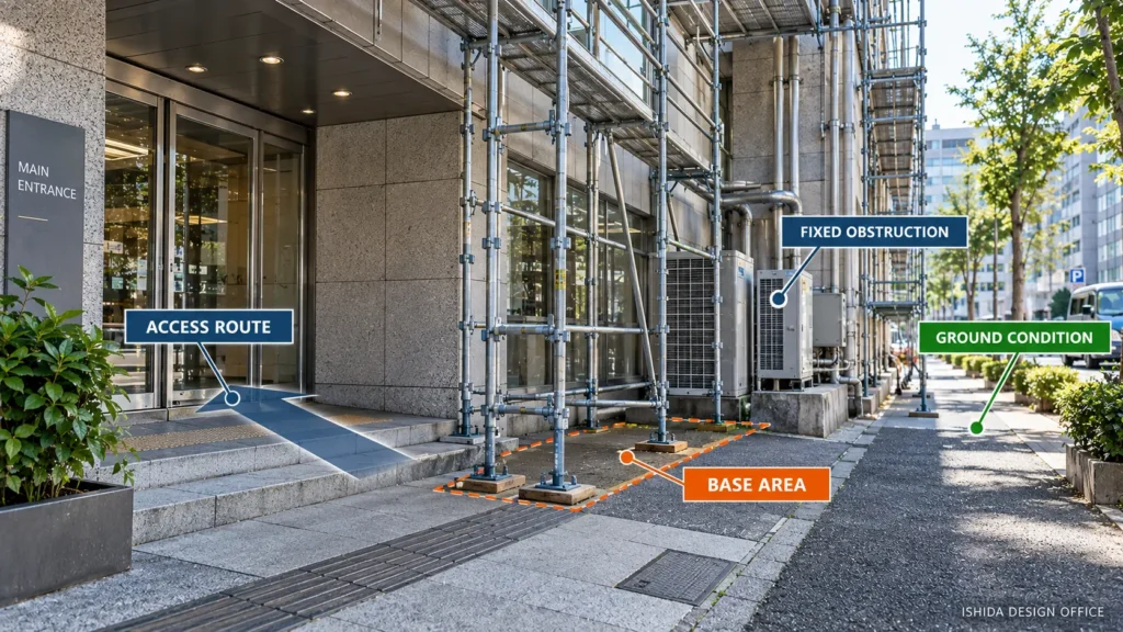
Ground-Level Conditions Are Part of the Obstruction Review
Looking upward for balconies, canopies and equipment is not enough.
The designer also needs to look down.
Before the scaffold layout is finalised, relevant questions include:
- What is the condition of the ground or supporting surface?
- Where can the scaffold actually begin?
- Are there steps, slopes or level changes?
- Are there structures or equipment at the base?
- Is sufficient erection space available?
- Does the proposed base position match the required distance from the building?
From my experience, two particularly useful pieces of information to establish early are the allowable relationship between the scaffold standards and the external wall, and clear photographic information showing the ground-level conditions where erection is expected to begin.
The exact solution depends on the scaffold system, supporting conditions and project requirements.
Under OSHA requirements for U.S. construction, supported scaffold poles, legs, posts, frames and uprights must bear on base plates and mud sills or another adequate firm foundation. HSE guidance in Great Britain likewise identifies the nature of the ground or supporting structure as important scaffold-planning information.
When Avoiding an Obstruction Changes the Structure
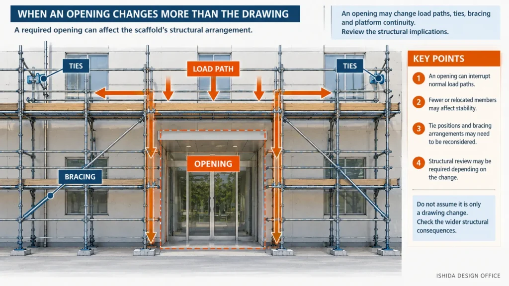
This is the point where an obstruction stops being only a coordination issue.
Suppose an entrance has to remain open. Moving or removing part of the normal scaffold arrangement may appear to solve the access problem.
But what else changed?
Potentially affected elements may include:
- standards;
- ledgers or transoms;
- platforms;
- braces;
- ties;
- load paths; and
- local stability.
IMPORTANT: If the scaffold arrangement changes to avoid an obstacle, review what else has changed rather than assuming the modification is only graphical.
In my own work, a requirement to create additional circulation resulted in another scaffold opening that required structural calculation. That experience reinforced a practical rule: where an opening changes the structural arrangement, its structural consequences must be checked rather than assumed.
This article intentionally does not explain proprietary calculation procedures or detailed bridging solutions. Those require project-specific engineering and are also a separate technical subject.
What Should Be Shown on the Scaffold Drawing?
Once a relevant site constraint has been identified, it should not disappear between the site survey and the issued scaffold drawing.
Depending on the project and the drawing’s purpose, relevant information may include:
- significant openings;
- entrances that must remain operational;
- known building projections;
- major fixed equipment affecting the scaffold;
- important façade geometry changes;
- required access routes;
- relevant base-level constraints;
- tie-related building interfaces where necessary;
- dimensions needed to understand the constraint; and
- references to details where a local condition needs separate explanation.
Not every pipe or piece of equipment belongs on every scaffold drawing.
The purpose is to communicate the conditions that materially affect the scaffold arrangement.
For a broader pre-issue review process, see Scaffold Drawing Checklist: What to Review Before Issue. The checklist article covers openings and obstacles as part of the overall drawing review; this article focuses specifically on identifying and planning around those site constraints.
Where a local condition needs separate explanation, see Scaffold Details Explained: When Standard Drawings Are Not Enough.
Common Planning Mistakes
Mistake 1: Designing Only From the Original Architectural Drawings
Why it matters: Existing buildings can contain later additions, changed wall conditions and equipment that were not included in the original information.
Better approach: Confirm drawing revision status and compare critical areas with current site information.
Mistake 2: Treating an Entrance as a Drafting Gap
Why it matters: An opening may affect several scaffold components and potentially the structural arrangement.
Better approach: Identify the opening requirement before fixing the surrounding layout and review all affected elements.
Mistake 3: Reviewing Only the Plan
Why it matters: Canopies, bay windows, changing façades and upper-level projections are three-dimensional problems.
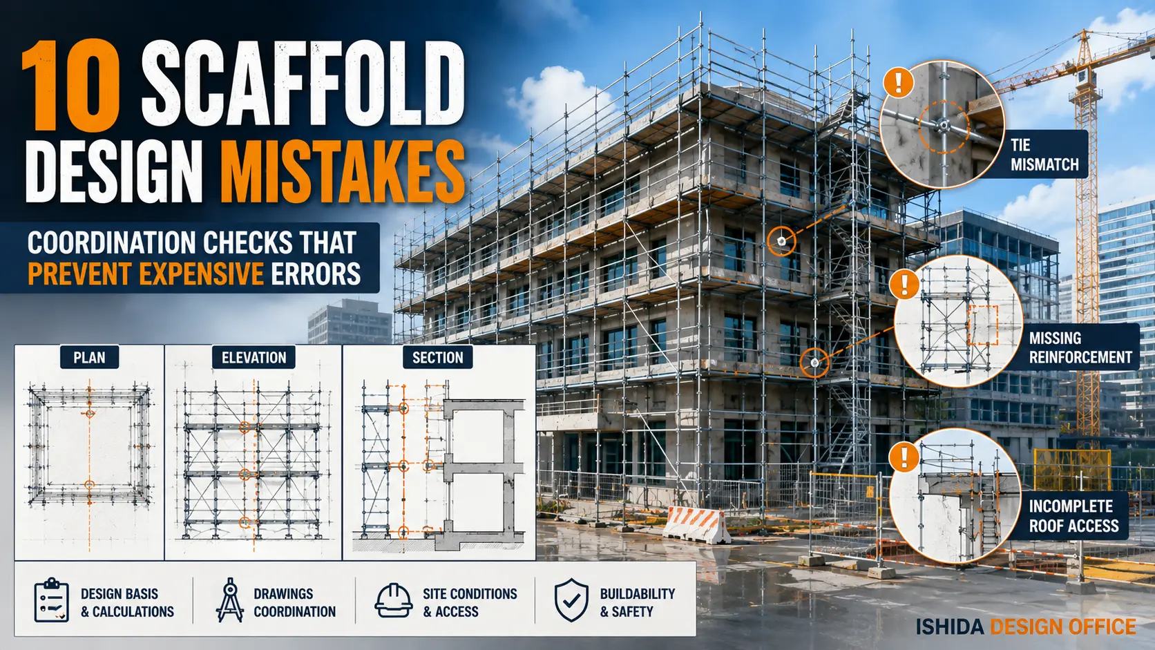
Better approach: Coordinate plan, elevation and section information.
Mistake 4: Assuming a Planned Tie Location Is Physically Available
Why it matters: The building-side connection may be affected by openings, façade construction or structural position.
Better approach: Verify the relevant building interface rather than relying only on a regular graphical pattern.
Mistake 5: Treating Site Photographs as Decoration
Why it matters: Current photographs can contain design information absent from drawings.
Better approach: Request photographs that answer specific scaffold-planning questions.
Mistake 6: Accepting Late Access Changes Without Design Review
Why it matters: A new pedestrian, vehicle or material route may alter the scaffold configuration.
Better approach: Reassess the affected arrangement and determine whether structural review is required.
Mistake 7: Ignoring the Ground While Studying the Façade
Why it matters: Even a well-coordinated elevation cannot be erected as planned if the base conditions or available erection space differ from the assumptions.
Better approach: Include ground and supporting conditions in the site-information review.
Practical Scaffold Openings & Obstructions Checklist
Use this as a high-level pre-design review. It should be adapted to the scaffold system, project, jurisdiction and design responsibility.
Drawing Information
- ☐ Latest available architectural information confirmed
- ☐ Relevant structural information identified
- ☐ Revision status checked
- ☐ Plan, elevation and section information compared
- ☐ Critical dimensions identified for confirmation
Existing Building
- ☐ Entrances and large openings identified
- ☐ Canopies and projections identified
- ☐ Balconies and bay windows considered
- ☐ Curved or changing façade geometry considered
- ☐ Later extensions or modifications checked
Services and Equipment
- ☐ Outdoor HVAC equipment checked
- ☐ Major pipes and ducts considered
- ☐ Signs and fixed equipment considered
- ☐ Other visible façade obstructions reviewed
Scaffold Interface
- ☐ Building-to-scaffold relationship reviewed
- ☐ Required working clearance considered
- ☐ Potential standard conflicts identified
- ☐ Tie connection conditions reviewed
- ☐ Bracing conflicts considered where relevant
- ☐ Working-platform continuity considered
Access and Site Use
- ☐ Required pedestrian routes identified
- ☐ Building entrances that must remain open identified
- ☐ Vehicle routes identified where relevant
- ☐ Material delivery/access requirements considered
- ☐ Erection and dismantling space considered
Ground and Support
- ☐ Ground/supporting condition identified
- ☐ Level changes or steps reviewed
- ☐ Ground-level obstructions checked
- ☐ Proposed scaffold starting position confirmed
Change Control
- ☐ Current site photographs reviewed
- ☐ Differences between drawings and actual conditions recorded
- ☐ Late changes to openings/access communicated
- ☐ Structural implications of layout changes reviewed
- ☐ Additional engineering/calculation identified where required
A Practical Lesson From Scaffold Design Work
Since beginning scaffold and temporary-works design work in Japan in 1998, one recurring lesson has been that the permanent building information is only one part of the scaffold-planning input.
I have encountered added canopies, outdoor equipment that did not appear on the available design information, façade conditions that affected tie planning, building projections that differed from the expected geometry, and access requirements that changed after the initial scaffold plan.
These situations are different, but the lesson is consistent:
The earlier the actual constraints are identified, the easier it is to incorporate them into a coherent scaffold plan.
Current drawings, purposeful site photographs, relevant dimensions and clear information about access and building use can therefore be just as important to scaffold planning as the initial bay arrangement.
That does not eliminate design changes. Construction projects change.
It does, however, reduce the risk of developing a detailed scaffold arrangement around assumptions that were never true on site.
FAQ
Can Scaffolding Be Planned From Architectural Drawings Alone?
Architectural drawings are an important starting point, but existing-site projects may contain later alterations, equipment, façade changes or access constraints not shown on the available drawings. Current site information should therefore be used where relevant to confirm critical conditions.
What Site Photographs Are Most Useful for Scaffold Planning?
Photographs are most useful when they answer specific questions: ground conditions, entrances, façade projections, equipment, available erection space, upper-level geometry and other constraints that affect the scaffold arrangement.
Does Every Scaffold Opening Require Structural Calculation?
Not necessarily. The need for calculation depends on how the opening affects the scaffold arrangement, the scaffold system, applicable design rules and project-specific conditions. If an opening changes structural members, support conditions, stability or load paths, the structural implications need appropriate review.
Why Can HVAC Units Cause Problems for Scaffold Drawings?
Outdoor units may occupy space intended for standards, platforms or other scaffold components. They are also frequently additions to existing buildings, so they may not appear on older architectural information.
Should Scaffold Tie Positions Be Checked Against the Building Structure?
Yes. A proposed tie position on a scaffold drawing must correspond to an appropriate building-side connection condition. The exact tie arrangement and connection requirements depend on the project, scaffold system, structure and applicable requirements.
What Should Be Done if Site Conditions Change After the Scaffold Is Designed?
If site conditions change after the scaffold has been designed, the affected arrangement should be reviewed rather than assuming the original design remains valid. Requirements differ by jurisdiction. For example, HSE guidance in Great Britain addresses design implications when alterations take a scaffold outside a recognised standard configuration, while OSHA requires scaffold alteration in U.S. construction to be carried out under the supervision and direction of a competent person.
Related Topics
- How to Review Scaffold Drawings for Site Constructability — the next step after site constraints have been incorporated into the scaffold plan.
- Scaffold Drawing Checklist: What to Review Before Issue — a broader final review of scaffold drawing information.
- Scaffold Ties Explained: Types, Spacing & Layout — a dedicated explanation of scaffold ties and building interfaces.
- Scaffold Details Explained: When Standard Drawings Are Not Enough — for local conditions requiring additional drawing detail.

Key Takeaways
- A scaffold should be planned around actual site conditions, not only the first building drawing received.
- Openings, canopies, HVAC equipment, projections, access routes and ground conditions can all influence the scaffold arrangement.
- Current site photographs can reveal important conditions absent from older drawings.
- Plan, elevation and section should be reviewed together where building geometry changes with height.
- Tie locations need to correspond to actual usable building-side connection conditions.
- A new opening or access requirement may be more than a drafting change if it alters the structural arrangement.
- Significant site constraints should remain visible in the scaffold documentation where they affect construction or design.
Conclusion
Openings and obstructions are not details to be added after the main scaffold has been planned. They are part of the design input.
Confirm the latest drawings, compare them with current site conditions, identify required openings and access routes, review the façade in three dimensions and understand the ground-level conditions before treating the scaffold layout as fixed.
When avoiding an obstruction changes the structural arrangement, the next step is not simply to redraw the scaffold. The affected design needs the appropriate level of technical review.
For the broader next step, continue with How to Review Scaffold Drawings for Site Constructability.
Official References
Health and Safety Executive — Scaffolds
Jurisdiction: Great Britain
Supports scaffold planning information including ground conditions, building information, pedestrian walkways, tie restrictions and alterations.
https://www.hse.gov.uk/construction/safetytopics/scaffoldinginfo.htm
Health and Safety Executive — Planning for Construction Work
Jurisdiction: Great Britain
Supports early gathering of site, access, ground and public-route information.
https://www.hse.gov.uk/construction/safetytopics/planning.htm
Health and Safety Executive — Protecting the Public
Jurisdiction: Great Britain
Supports access, boundaries and pedestrian/vehicle interfaces around construction work.
https://www.hse.gov.uk/construction/safetytopics/publicprotection.htm
Health and Safety Executive — Temporary Works FAQs
Jurisdiction: Great Britain
Supports checking that assumptions behind standard temporary-works solutions remain valid for actual site conditions.
https://www.hse.gov.uk/construction/faq-temporary-works.htm
Occupational Safety and Health Administration — 29 CFR 1926.451, General Requirements
Jurisdiction: United States
Supports requirements relating to supported-scaffold foundations and scaffold alteration in U.S. construction.
https://www.osha.gov/laws-regs/regulations/standardnumber/1926/1926.451
Last Verified: September 2026
Regulations, official guidance and manufacturer documentation may change. Always confirm the current requirements applicable to the project location, scaffold system and intended use.
This article is general technical information and is not a substitute for project-specific engineering, applicable law, contract documents, project specifications, manufacturer instructions or competent professional review.
About the Author
ISHIDA DESIGN OFFICE brings more than 30 years of practical experience in Japan, specializing in scaffolding design, temporary works planning, CAD drafting, quantity estimation, and construction support.
Drawing on experience from residential, commercial, and industrial projects, he shares practical insights that emphasize not only sound engineering design but also buildability, safety, and real-world jobsite application.
At Scaffold Design Hub, he combines practical experience from Japan with official guidance and technical resources from government agencies, manufacturers, and industry organizations around the world to provide reliable, practical information for construction professionals.
To learn more, visit the About page. For questions or project inquiries, please use the Contact page.