A scaffold drawing can look clear at first glance and still be misunderstood on site.
A supervisor may understand the elevation but miss the scaffold-to-building clearance shown in a section. An estimator may count bays correctly but overlook a special loading area. A scaffolder may identify the stair tower but not realise that a detail changes the standard arrangement at one location.
After more than 30 years of working with scaffold drawings, CAD drafting, temporary works planning and material estimation, I have learned that reading a scaffold drawing correctly means more than understanding individual lines and symbols.
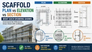
You need to understand how the different views work together.
In practice, I recommend three basic principles:
- Never read the plan, elevation or section in isolation.
- Check the drawing status and revision before studying the scaffold itself.
- Where information appears unclear or contradictory, do not guess—raise the question before erection begins.
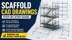
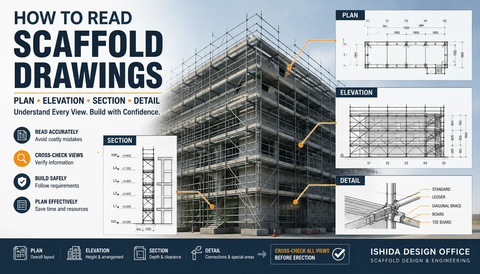
This guide explains how to read scaffold plans, elevations, sections and detail drawings, and how to cross-check them as one coordinated set of construction information.
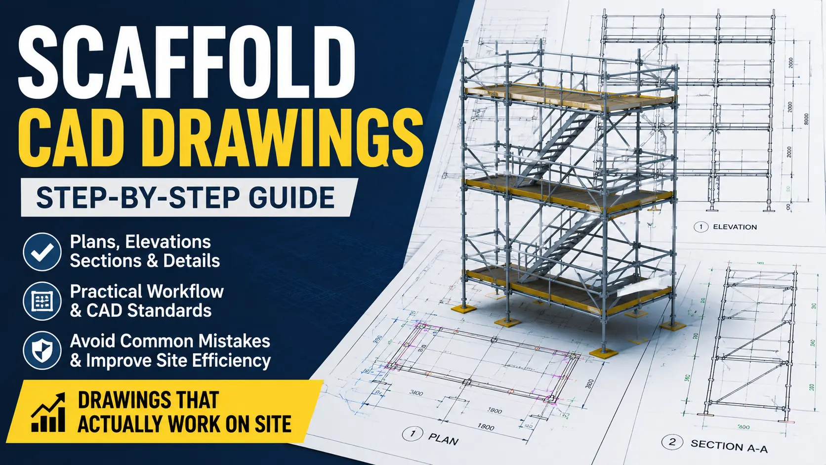
If you are interested in how these drawings are created rather than how they are read, see our practical guide to How to Create Scaffold CAD Drawings That Actually Work on Site.
What You Will Learn
By the end of this guide, you should understand:
- Where to start when you receive a scaffold drawing
- How to read a scaffold plan
- How to read an elevation
- What a section tells you that other views cannot
- How to follow detail references
- How to interpret dimensions, notes and symbols
- How to cross-check different views
- Common drawing-reading mistakes
- A practical review sequence you can use on site
Important Safety Notice
This article is for general educational purposes. A drawing should not be treated as proof that a scaffold is structurally adequate or suitable for a particular project.
Requirements vary by country, jurisdiction, and project.
Always follow local laws, project specifications, engineering requirements, risk assessments, and the scaffold manufacturer’s current instructions.
Why Reading Scaffold Drawings Correctly Matters
A scaffold drawing is a communication document.
It connects the designer, scaffold contractor, site supervisor, estimator, safety team, project manager and the people who will ultimately erect and use the scaffold.
That communication breaks down when different people interpret the same drawing differently.
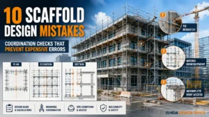
In my experience, some of the most important drawing problems are not difficult engineering calculations. They are simple coordination problems:
- The plan and elevation show different numbers of bays.
- A stair tower appears in one view but its access route is unclear in another.
- A canopy is visible in plan but its height is not understood.
- A special bracket is shown in section but overlooked during material take-off.
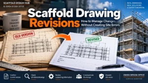
- A revised tie arrangement appears on one sheet while an older sheet remains in circulation.
- A detail reference exists, but nobody follows it to the relevant detail.
These may appear to be small drafting issues, but on site they can lead to rework, missing materials, access problems, delays and potentially unsafe decisions.
Official guidance also reinforces the importance of clear design information. HSE states that, depending on scaffold complexity, an assembly, use and dismantling plan may be required and that information relevant to the scaffold design can include critical dimensions, loads, access, sheeting or netting, tie restrictions and relevant drawings. (HSE)
The objective when reading a drawing is therefore not simply to answer:
“What does this line mean?”
A better question is:
“Can I understand what is intended to be built, where it will be built, and where the arrangement changes?”
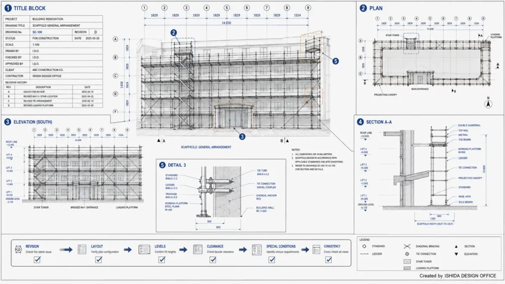
Start With the Title Block — Not the Scaffold
In my drawing review work, I first check whether the drawings are consistent with one another and whether there have been any major changes to the existing site conditions. I then compare the drawings with available site photographs. This helps me identify differences between the information shown on the drawings and the actual conditions before proceeding with the scaffold planning.
When I receive a scaffold drawing, I do not recommend starting by looking at the scaffold itself.
Start with the title block.
Before relying on the drawing, identify information such as:
- Project name
- Drawing title
- Drawing number
- Drawing status
- Revision number
- Revision date
- Scale
- Date
- Drawn by
- Checked by
- Relevant calculation or document references
This sounds administrative, but it can be technically important.
A beautifully prepared drawing may still be the wrong drawing.
For example, you may be looking at:
Preliminary
instead of:
For Construction
Or you may have Revision 2 while another member of the project team is using Revision 4.
During drawing reviews, I consider revision control part of the technical review—not something separate from it.
Before reading further, ask:
Is this the correct drawing, and is it the latest approved version I should be using?
If you cannot answer that question confidently, resolve it before relying on the information shown.
How to Read a Scaffold Plan
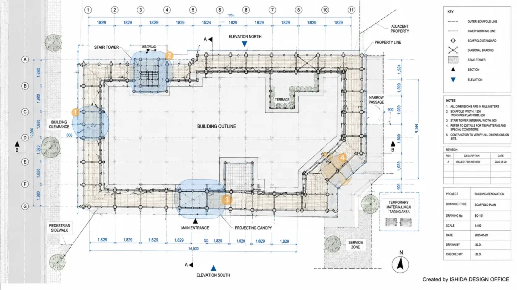
A scaffold plan is essentially a view looking down from above.
For many facade scaffolds, the plan is the best place to understand the scaffold’s horizontal relationship with the building and surrounding site.
Do not treat it simply as a footprint.
A good plan may help you understand:
- Scaffold position
- Building outline
- Bay arrangement
- Standard locations
- Scaffold width
- Distance from the facade
- Corners and returns
- Entrances
- Stair towers
- Ladder access
- Loading areas
- Canopies
- Balconies
- Roads
- Property boundaries
- Pedestrian routes
- Obstructions
- Special or cantilevered areas
Start With the Building
First identify the building or structure.
Then identify the scaffold around it.
This sounds obvious, but complex architectural backgrounds can make the scaffold lines difficult to distinguish from building lines.
Ask:
Where does the building end and the scaffold begin?
Next, follow the scaffold around the building.
Look for changes in:
- Bay length
- Scaffold width
- Building line
- Distance from the facade
- Access arrangement
- Corner configuration
Look for Constraints
This is where practical site knowledge becomes important.
A regular row of scaffold bays may look simple on paper, but the actual building may contain:
- Doors
- Vehicle entrances
- Canopies
- Balconies
- Pipework
- Equipment
- Narrow passages
- Neighbouring property
- Public access
In more than three decades of scaffold drawing work, I have found that these interfaces often deserve more attention than the repetitive standard bays.
Where the building or site changes, slow down and read the drawing more carefully.
How to Read a Scaffold Elevation
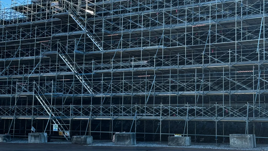
An elevation shows the scaffold from the side or front.
If the plan tells you where the scaffold goes horizontally, the elevation helps you understand what happens vertically.
Typical information may include:
- Overall scaffold height
- Bay arrangement
- Lift heights
- Working-platform levels
- Standards
- Ledgers
- Bracing
- Ties
- Guardrails
- Toe boards
- Stair or ladder arrangements
- Loading platforms
- Hoists
- Protection fans
- Sheeting or netting
- Roof-level arrangements
- Special strengthening
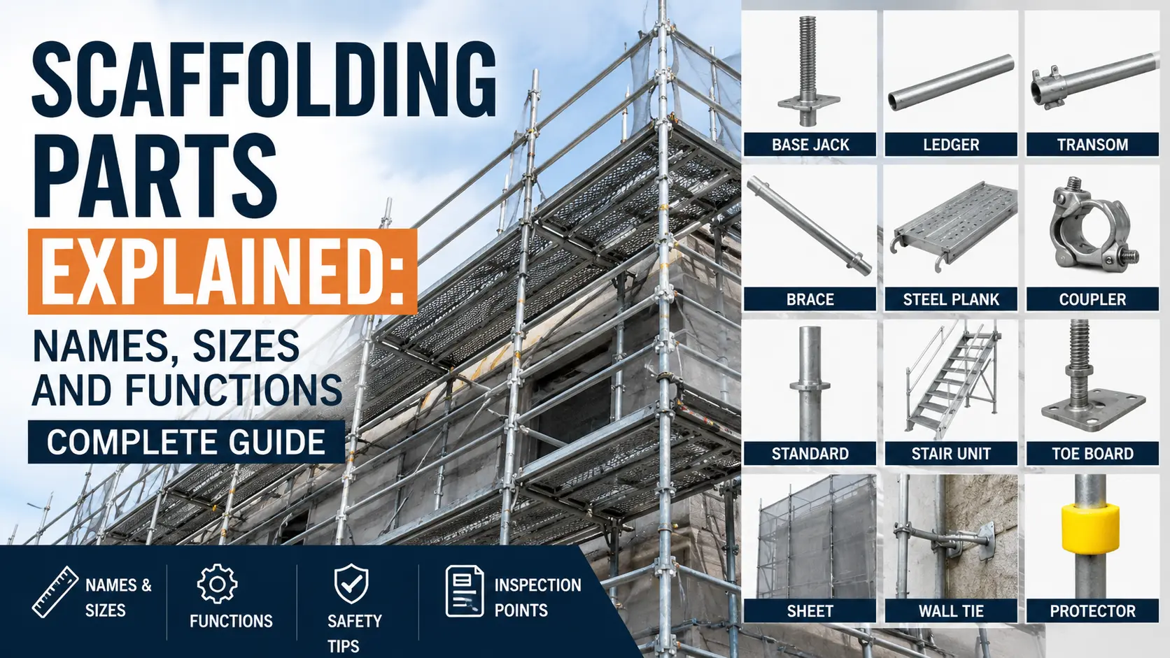
If you are not familiar with the individual components shown on scaffold drawings, see Scaffolding Parts Explained: Names, Sizes and Functions (Complete Guide) for a practical explanation of common scaffold parts and their functions.
Do Not Read the Scaffold Without Reading the Building
One of the first things I look at is the relationship between scaffold levels and building levels.
Compare the scaffold with:
- Floors
- Windows
- Balconies
- Canopies
- Roof lines
- Work areas
- Entrances
A working platform may be correctly drawn as part of the scaffold system but still be poorly positioned for the intended work if the relationship with the building has not been properly understood.
Check the Bay Count
This is a simple but valuable check.
If the plan shows eight bays along one facade, does the corresponding elevation also show eight?
If not, determine why.
There may be a legitimate reason—but the two drawings should not silently contradict each other.
The same applies to stair towers, loading areas and other major features.
How to Read a Scaffold Section
When reviewing a scaffold section, one of my main concerns is the structure of the existing building. I check what the structural elements are made of, with particular attention to the walls. I then consider whether scaffold ties can be installed at the intended locations. The drawing may show a proposed tie position, but the actual wall construction and supporting structure must be understood before the suitability of that connection can be confirmed.
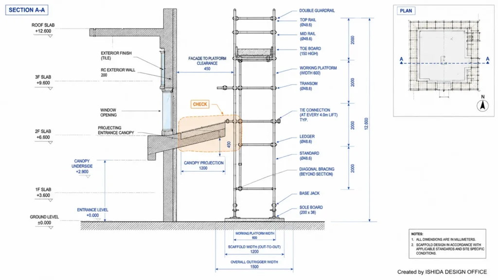
A section is one of the most useful drawings when the plan and elevation do not tell the complete story.
Imagine cutting through the scaffold and building and looking at the cut face.
A section can reveal information such as:
- Scaffold width
- Distance between scaffold and facade
- Working-platform position
- Brackets
- Cantilever arrangements
- Guardrails
- Building projections
- Canopy relationships
- Floor levels
- Roof edges
- Ground levels
- Tie relationships
- Clearance around obstacles
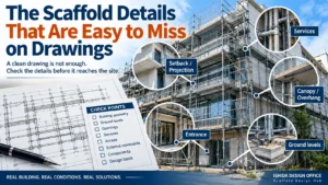
This is why I pay particular attention to sections around unusual areas.
A plan may tell you that a canopy exists.
An elevation may tell you its approximate level.
But a section can show the relationship between:
building → canopy → scaffold → platform → clearance
in a way that the other views cannot.
When Should You Look for a Section?
Pay particular attention when you see:
- Canopies
- Balconies
- Brackets
- Cantilevers
- Bridged openings
- Sloping ground
- Roof edges
- Loading bays
- Stair-tower connections
- Changes in scaffold width
- Pedestrian passages
- Vehicle access
From my drawing experience, a useful rule is:
If you cannot confidently understand the relationship between the scaffold and the building from the plan and elevation, look for a section.
If no section or detail exists and the arrangement remains unclear, ask for clarification rather than making an assumption on site.
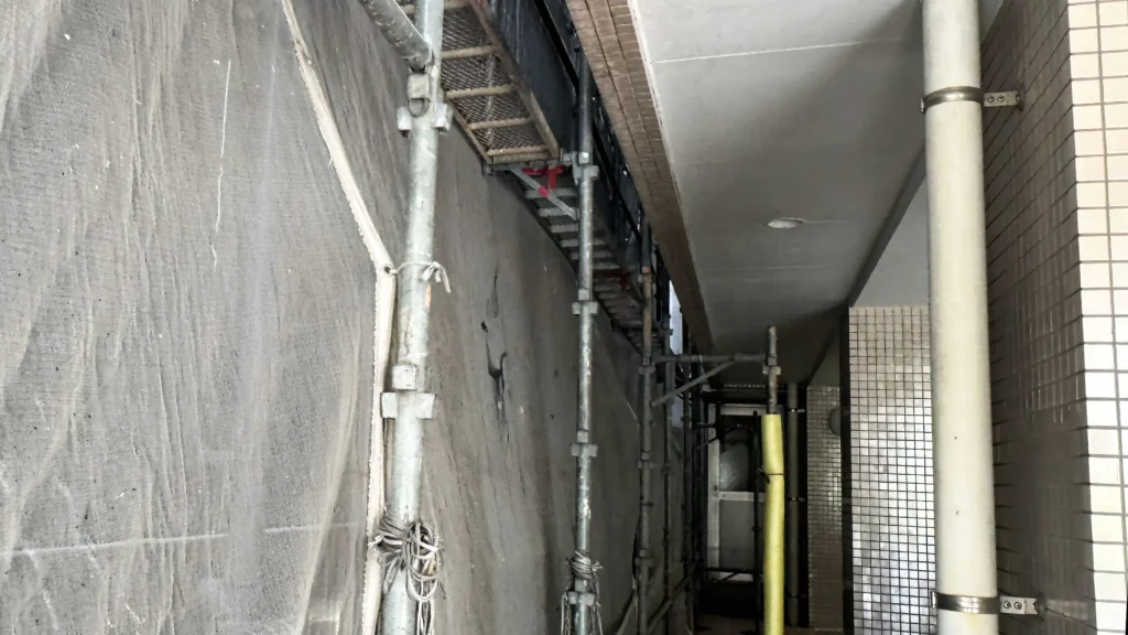
How to Read Scaffold Detail Drawings
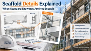
Details show areas where the general plan, elevation or section does not provide enough information.
They may be enlarged views or separate drawings.
Typical scaffold details may cover:
- Special tie arrangements
- Brackets
- Cantilevers
- Bridging beams
- Loading platforms
- Roof-level scaffolds
- Stair connections
- Protection fans
- Sheeting terminations
- Openings
- Non-standard support arrangements
- Interfaces between different scaffold systems
The important skill is not simply reading the detail.
It is understanding where that detail applies.
Follow the Reference
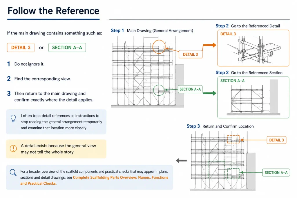
If the main drawing contains something such as:
DETAIL 3
or
SECTION A-A
do not ignore it.
Find the corresponding view.
Then return to the main drawing and confirm exactly where the detail applies.
I often treat detail references as instructions to stop reading the general arrangement temporarily and examine that location more closely.
A detail exists because the general view may not tell the whole story.
For a broader overview of the scaffold components and practical checks that may appear in plans, sections and detail drawings, see Complete Scaffolding Parts Overview: Names, Functions and Practical Checks.
Understanding Dimensions, Symbols and Notes
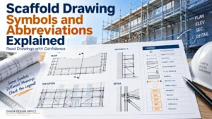
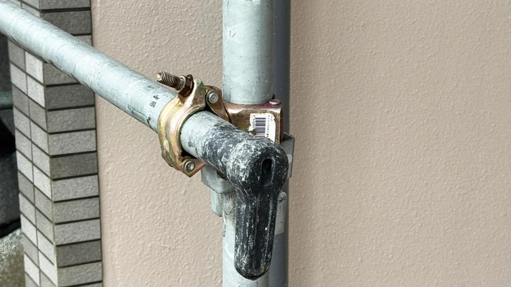
Do not assume that every scaffold drawing uses identical symbols.
Company conventions, software, scaffold systems and project standards differ.
Where a legend is provided, read it.
Important dimensions may include:
- Overall scaffold length
- Bay lengths
- Scaffold width
- Scaffold-to-building distance
- Overall height
- Lift heights
- Opening dimensions
- Canopy levels
- Stair positions
- Cantilever dimensions
But more dimensions do not automatically mean a better drawing.
During drawing reviews, I am more interested in whether the critical dimensions are clear and consistent than in how many dimensions have been added.
Read Notes Carefully
A note may apply to:
- One location
- One elevation
- One detail
- An entire drawing
- The complete drawing set
Do not assume a general note overrides a specific detail without checking the document hierarchy and project requirements.
Likewise, abbreviations should not be guessed.
If a symbol, abbreviation or note is unclear, use the legend or request clarification.
How to Cross-Check Plan, Elevation, Section and Details
In my own scaffold planning work, I begin by understanding the site layout and available space. I then review the floor plans for each level, paying particular attention to setbacks and changes in the building footprint. Next, I examine the sections to understand the building structure and its relationship with the proposed scaffold. Finally, I review the elevations to confirm the overall vertical arrangement. This sequence helps me identify building conditions that may affect scaffold positioning and planning.
This is the most important part of reading scaffold drawings.
Do not think of the four views as separate drawings.
Think of them as different ways of describing the same scaffold.
A practical sequence is:
Plan → Elevation → Section → Detail → back to Plan
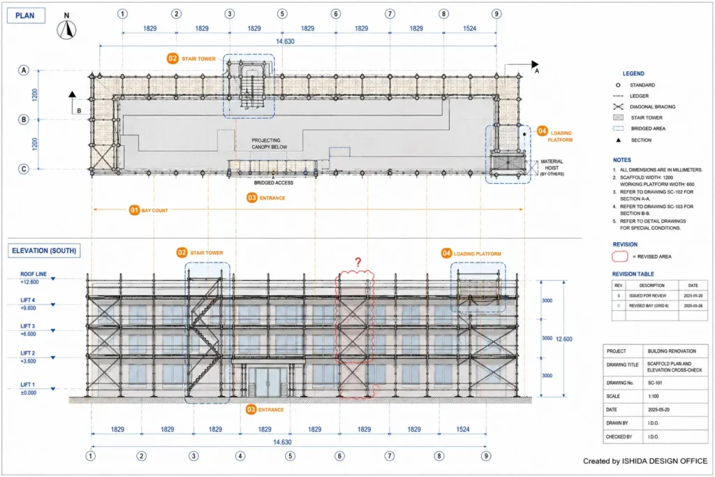
For example, suppose the plan shows a stair tower.
Find that same stair tower on the elevation.
Then ask:
- Does its position match?
- Does the stair direction make sense?
- Are the landings at usable levels?
- Is there a nearby canopy?
- Is access from ground level clear?
- Is a section provided?
- Does a detail change the standard arrangement?
Now repeat the process for other important features.
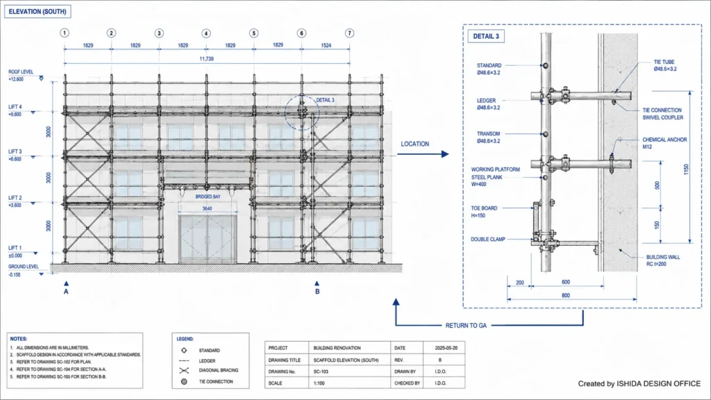
Cross-Check These Items
| Plan | Elevation / Section / Detail |
| Bay arrangement | Same number and position of bays |
| Stair tower | Vertical access and landing levels |
| Loading bay | Height, platform and protection |
| Canopy | Vertical clearance |
| Building offset | Scaffold-to-facade clearance |
| Special area | Relevant section/detail |
| Tie location | Intended vertical/horizontal arrangement |
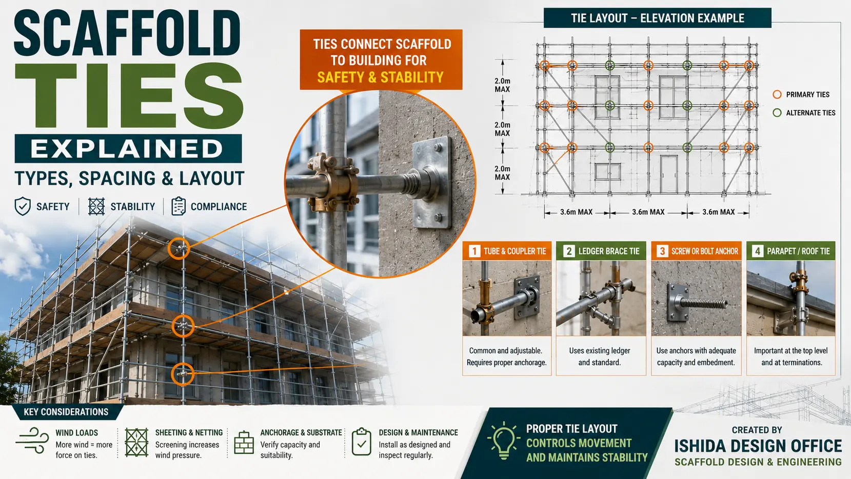
| Entrance | Clear working and pedestrian access |
A drawing should behave like one coordinated information system.
If one view tells a different story from another, investigate the difference.
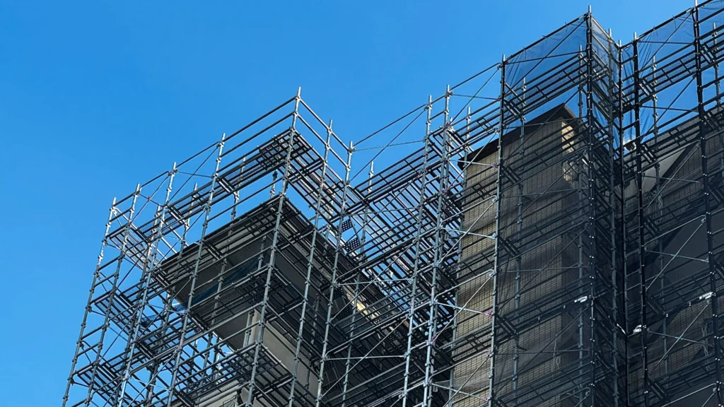
Japanese Practice Note
In many Japanese renovation projects I have worked with, the available space around an existing building can be very limited. This makes it especially important to read the drawing set as coordinated information rather than relying on one view alone.
Under these conditions, I pay particular attention to the places where the regular scaffold arrangement changes. An entrance, balcony, setback, different bay arrangement, restricted area or change in building geometry may be shown clearly in one view but be easy to overlook in another.
From more than 30 years of scaffold drawing and estimation work, I have found that these transition points deserve an extra cross-check between the plan, elevation, section and relevant details. They can affect how the drawing is interpreted, how quantities are understood and whether the intended arrangement is communicated clearly to the site team.
For more practical lessons drawn from this experience, see What 30 Years of Scaffold Design Has Taught Me.
Another useful habit is to compare the drawing with available site photographs and confirmed project information. The purpose here is not to carry out a full constructability review, but to confirm that the views being read correspond to the building and conditions they are intended to describe.
This approach is not unique to Japan. Wherever projects involve irregular geometry or restricted sites, focus attention on interfaces, changes and non-standard areas, then confirm that the different drawing views describe them consistently.
Requirements vary by country, jurisdiction, and project. Always confirm applicable local regulations, project specifications and the scaffold manufacturer’s current instructions.
International Perspective
There is no single worldwide scaffold-drawing standard that can replace local requirements.
However, several official authorities emphasise principles that are highly relevant when reading scaffold drawings.
United States — OSHA
OSHA’s construction scaffold requirements are contained in 29 CFR 1926 Subpart L. OSHA also provides Appendix E drawings and illustrations showing particular scaffold types, components, bracing patterns and tie-spacing patterns. (OSHA — 1926 Subpart L)
OSHA also establishes specific capacity, design, platform, access and other requirements for scaffolds. These requirements should not be replaced by assumptions made from a drawing alone. (OSHA — 1926.451 General Requirements)
United Kingdom — HSE
HSE states that scaffolds should be designed, erected, altered and dismantled by competent people under appropriate supervision. It also distinguishes recognised standard configurations from arrangements that require bespoke design. HSE specifically identifies information such as scaffold dimensions, working loads, access, sheeting, tie restrictions, ground conditions and relevant drawings as part of the planning and design process. (HSE — Scaffolds)
Australia — Safe Work Australia
Safe Work Australia provides guidance on managing risks associated with scaffolds and scaffolding work, including falls, scaffold collapse, falling objects and work near electrical hazards. It also makes clear that WHS laws are regulated and enforced by the Commonwealth, states and territories, so the requirements applicable to the relevant jurisdiction should always be confirmed. (Safe Work Australia — Scaffolds and Scaffolding Work General Guide)
New Zealand — WorkSafe
WorkSafe New Zealand provides good-practice guidance covering scaffold design, erection, use, inspection and maintenance. Its guidance emphasises that scaffolding should be fit for purpose and appropriate for the work being carried out. (WorkSafe New Zealand — Scaffolding in New Zealand)
Manufacturer Information
System-scaffold drawings should also be read alongside the current technical documentation for the scaffold system actually being used.
For example, Layher provides official technical documentation including approvals, assembly and use instructions, technical information, drawings and other product documentation. (Layher — Official Technical Downloads)
Common Mistakes When Reading Scaffold Drawings
In practical drawing reviews, these are the mistakes I would particularly watch for:
- Starting with the scaffold instead of checking the revision.
A technically correct superseded drawing is still the wrong drawing to use. - Reading only the elevation.
Elevations are easy to understand visually, but they do not fully explain horizontal clearances, boundaries or access routes. - Ignoring sections.
Important relationships around canopies, brackets and building offsets may only become clear in section. - Ignoring detail references.
The main drawing may deliberately omit information because it is shown elsewhere. - Assuming symbols are universal.
Check the legend and project conventions. - Reading dimensions without checking the view they belong to.
A dimension that makes sense in plan may not explain the vertical condition. - Failing to compare plan and elevation bay counts.
Simple coordination errors can affect erection and material quantities. - Not checking the building information.
Scaffold geometry cannot be understood properly without understanding the structure around which it is erected. - Treating notes as a substitute for graphics.
If an important arrangement remains unclear, a note may not be enough. - Guessing when information is missing.
This is the most important mistake to avoid. If a drawing leaves a safety-critical or technically important condition uncertain, obtain clarification.
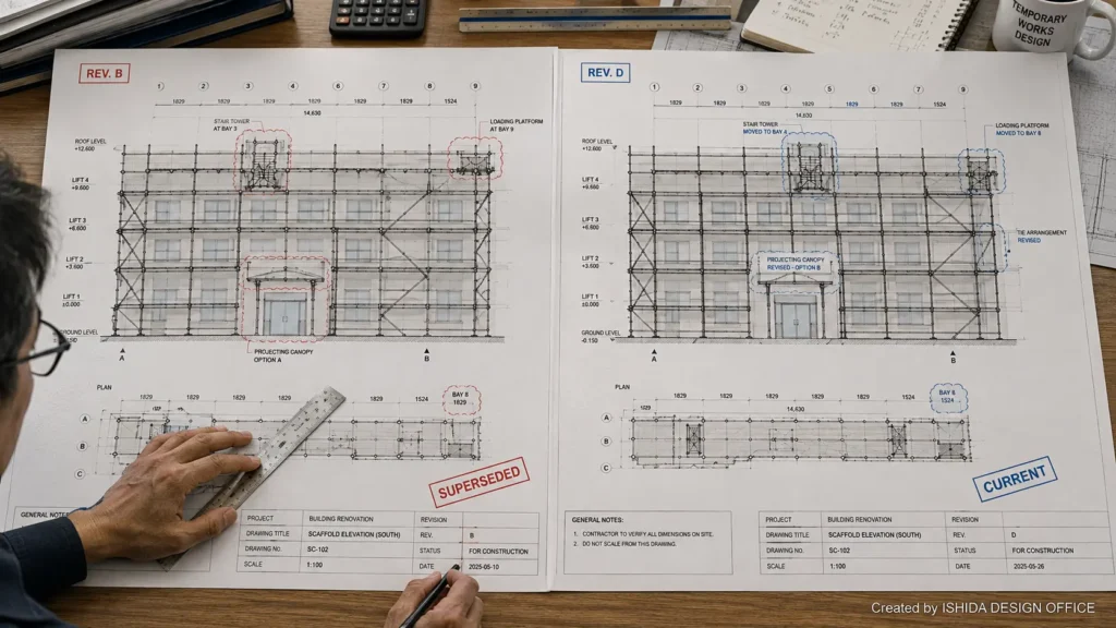
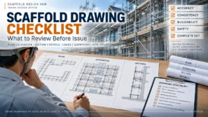
Practical Scaffold Drawing Reading Checklist
Before using a scaffold drawing, I recommend checking:
- Correct project and drawing number
- Latest applicable revision
- Drawing status
- Plan orientation
- Building outline
- Scaffold footprint
- Bay arrangement
- Scaffold width
- Distance from the building
- Entrances and access routes
- Stair and ladder locations
- Loading areas
- Working-platform levels
- Overall scaffold height
- Lift arrangement
- Bracing
- Tie information
- Canopies and balconies
- Special brackets or cantilevers
- Section references
- Detail references
- Notes and legend
- Special or non-standard areas
- Relationship between plan and elevation
- Relationship between plan/elevation and sections
- Relevant manufacturer information
- Relevant design/calculation references where applicable
- Latest project and site information
If something important cannot be answered from the drawing, do not fill the gap with an assumption.
Record the question and obtain clarification from the appropriate responsible person.
Example Scenario: The Plan Looks Correct, but the Section Reveals a Problem
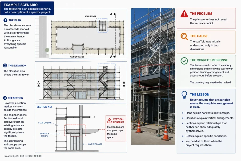
The following is an example scenario, not a description of a specific project.
A site engineer receives a scaffold drawing for renovation work.
The plan shows a normal run of facade scaffold with a stair tower near the main entrance.
At first glance, everything appears reasonable.
The elevation also shows the stair tower.
However, a section marker is shown beside the entrance.
The engineer opens Section A-A and discovers that an existing entrance canopy projects significantly from the facade.
The stair landing and canopy occupy the same area.
The Problem
The plan alone does not reveal the vertical conflict.
The Cause
The scaffold was initially understood only in two dimensions.
The Correct Response
The team should confirm the canopy dimensions and review the stair-tower position, landing arrangement and access route before erection.
The drawing may need to be revised.
The Lesson
Never assume that a clear plan means the complete arrangement is clear.
Plans explain horizontal relationships.
Elevations explain vertical arrangements.
Sections explain relationships that neither can show adequately by themselves.
Details explain specific conditions.
You need all of them when the project requires them.
Related Topics
If you want to understand how scaffold drawings are produced rather than read, continue with How to Create Scaffold CAD Drawings That Actually Work on Site.
Other useful topics to develop alongside this guide include:
- Scaffolding Parts Explained: Names, Sizes and Functions
- Scaffold Dimensions Explained: Bay Length, Lift Height, Width & Standards
- How to Estimate Scaffolding Materials from Drawings
- Scaffold Tie Patterns and Drawing Symbols
- Common Scaffold Drawing Mistakes
- How to Review Scaffold Drawings for Site Constructability — Continue from understanding the drawing set to reviewing whether the proposed scaffold can work under actual site conditions.
Together, these topics build the connection between drawing → understanding → checking → estimating → construction.
Key Takeaways
- Check the title block and revision before reading the scaffold itself.
- Use the plan to understand horizontal layout and site relationships.
- Use elevations to understand height, lifts, platforms, bracing, ties and access.
- Use sections and details wherever the standard views do not fully explain the arrangement.
- Cross-check all views rather than reading them independently.
Most importantly:
A scaffold drawing should reduce uncertainty—not create new assumptions.
Conclusion
After more than 30 years of working with scaffold drawings, CAD drafting and material estimation, I have found that good drawing review is often less about finding complicated problems and more about noticing small inconsistencies before they reach the site.
A bay that does not match.
A section that has not been checked.
An old revision.
A stair tower that conflicts with a building feature.
A detail that everyone overlooked.
Before using your next scaffold drawing, ask:
“Do the plan, elevation, section and details all describe the same scaffold?”
If the answer is not clearly yes, investigate before proceeding.
That simple habit can improve communication between designers, scaffold contractors, supervisors, estimators and site teams.
References
The following primary and technical sources provide supporting guidance for the scaffold design, planning, access, loading, stability and documentation principles discussed in this article.
Official Government and Regulatory Sources
-
Health and Safety Executive (HSE) — Scaffolds
UK guidance covering scaffold planning, design information, critical dimensions, working loads, access, ties, special configurations and relevant drawings.
HSE — Scaffolds -
Occupational Safety and Health Administration (OSHA) — 29 CFR 1926 Subpart L: Scaffolds
U.S. construction safety requirements for scaffold capacity, platforms, access, fall protection and scaffold use.
OSHA — 29 CFR 1926 Subpart L: Scaffolds -
Occupational Safety and Health Administration (OSHA) — Appendix A: Scaffold Specifications
Technical scaffold specifications and guidance covering scaffold members, spacing, bracing, tie-ins, platforms and various scaffold configurations.
OSHA — Appendix A: Scaffold Specifications -
Safe Work Australia — Scaffolds and Scaffolding Work General Guide
Guidance on scaffold design, planning, risk management, foundations, supporting structures, erection, alteration, dismantling and safe use.
Safe Work Australia — Scaffolds and Scaffolding Work General Guide
Manufacturer Technical Information
-
PERI — Scaffolding Systems / PERI UP
Manufacturer information for modular scaffolding systems, working scaffolds, access solutions and system-specific applications.
PERI — Scaffolding Systems
Related Articles

Last Verified: August 2026
All external references and official guidance cited in this article were checked for accessibility at the time of writing.
Scaffold requirements, regulations, guidance and manufacturer documentation may vary by country, jurisdiction, scaffold system and project, and may change over time. Readers should confirm the latest requirements through the relevant authority, local regulator, project specifications, engineering information and the current technical documentation for the scaffold system being used.
About the Author
Kenzo Ishida is the founder of ISHIDA DESIGN OFFICE. With more than 30 years of practical experience in Japan, he has worked in scaffold design, temporary works planning, CAD drafting, quantity estimation and construction support.
His experience includes reviewing scaffold plans, elevations, sections and detail drawings for real construction projects, with particular attention to buildability, site constraints, access, material quantities and coordination between drawings.
At Scaffold Design Hub, he combines practical experience from Japan with official guidance and technical resources from government agencies, regulators, manufacturers and industry organizations to provide practical information for scaffold designers, site engineers, supervisors, estimators and other construction professionals.
To learn more, visit the About page. For questions or project inquiries, please use the Contact page.