A scaffold foundation has one essential job: transfer the loads from the scaffold into a supporting surface that can carry them without unacceptable settlement, movement or loss of stability.
That sounds simple, but the supporting conditions beneath a scaffold can vary significantly. Concrete, asphalt, compacted ground, gravel, fill and sloping ground should not automatically be treated as equivalent surfaces.
For a designer, the important question is therefore not simply:
“Is there a base plate under the standard?”
The more useful question is: “Where does the load go after it reaches the base plate, and is the complete supporting system appropriate for the actual site conditions?”
This guide explains the roles of base plates, sole boards, adjustable bases and supporting surfaces, and identifies the ground-condition information that should be checked and communicated before a scaffold base arrangement is accepted.
Why Scaffold Base Design Matters
A scaffold can have correctly arranged standards, ledgers, working platforms, bracing and ties, yet still develop problems if its foundation cannot adequately support the loads delivered to it.
For supported scaffolds in the United States, OSHA requires poles, legs, posts, frames and uprights to bear on base plates and mud sills or another adequate firm foundation. OSHA also requires the footings to be level, sound and rigid, and capable of supporting the loaded scaffold without settling or displacement.
OSHA 29 CFR 1926.451 — General Requirements
Safe Work Australia similarly states that scaffold foundations should be designed and constructed to carry and distribute the full scaffold weight, including dead and live loads, and that ground conditions and weather effects—particularly wind and rain—should be considered.
IMPORTANT: These are jurisdiction-specific sources rather than universal design rules. They illustrate a common engineering principle: the scaffold and its supporting surface must be considered as a connected load path.
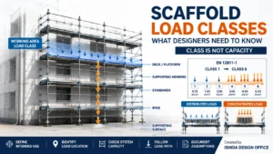
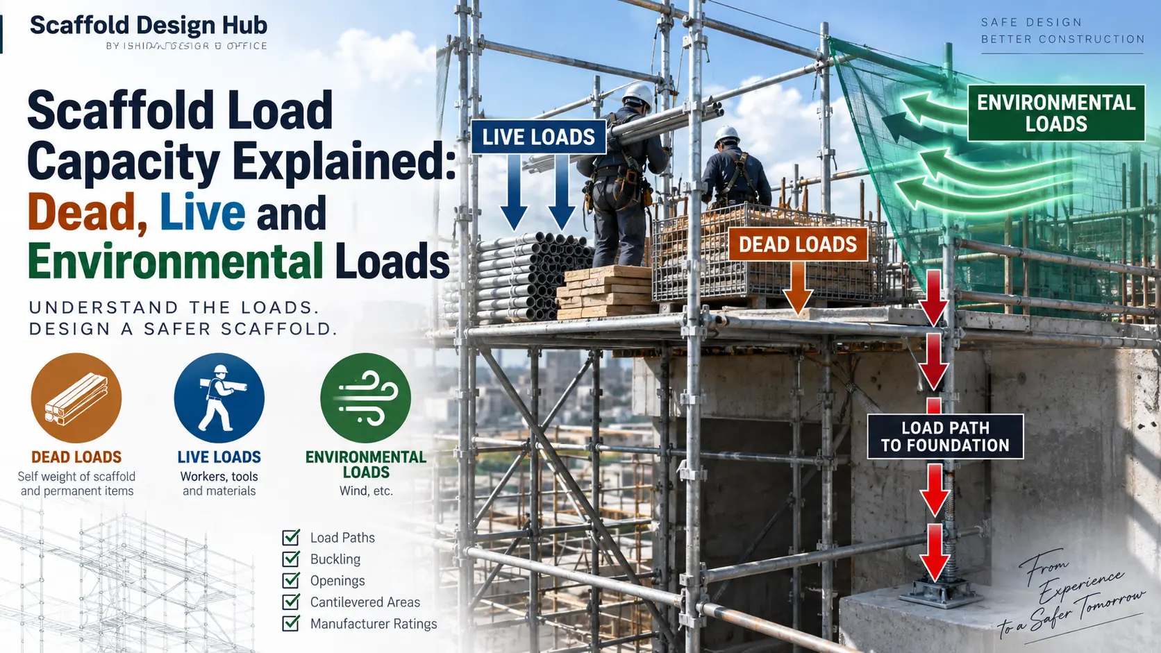
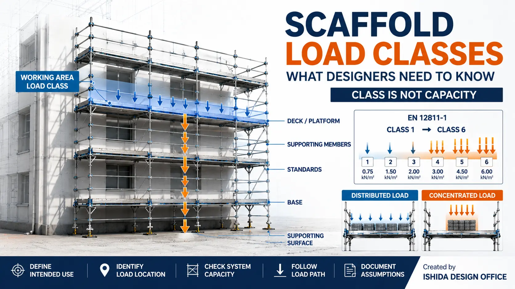
For a broader explanation of scaffold loading, see Scaffold Load Capacity Explained: Dead, Live and Environmental Loads.
Understanding the Scaffold Load Path
At the base of a typical supported scaffold, the vertical load path can be represented conceptually as:
Scaffold standard / leg
↓
Adjustable base or base plate
↓
Sole board, where required
↓
Supporting surface
↓
Underlying ground or supporting structure
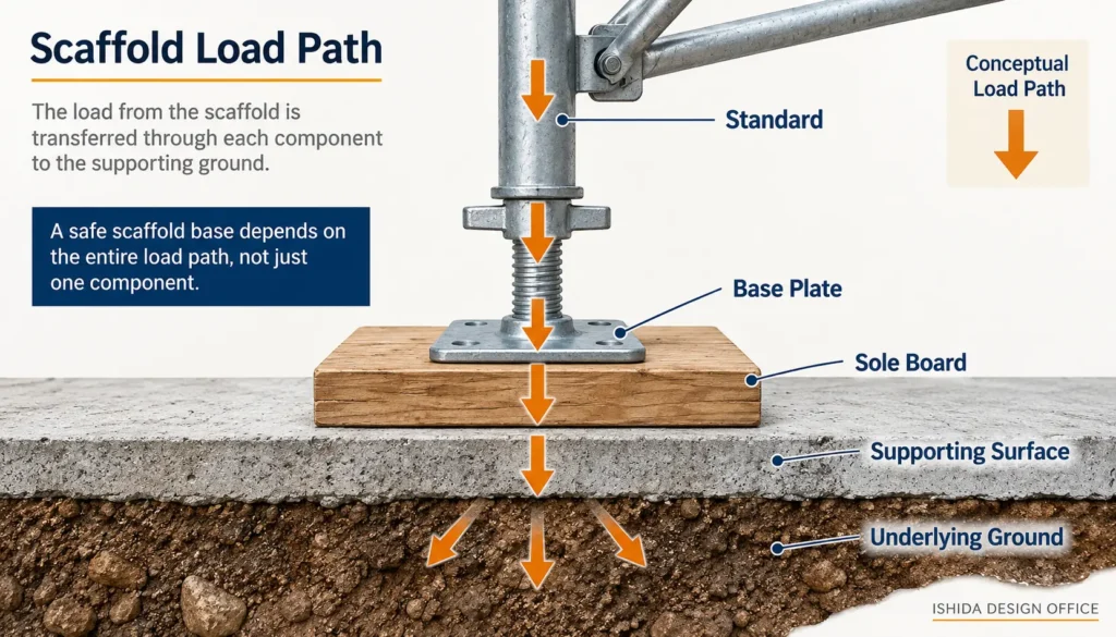
Each layer matters.
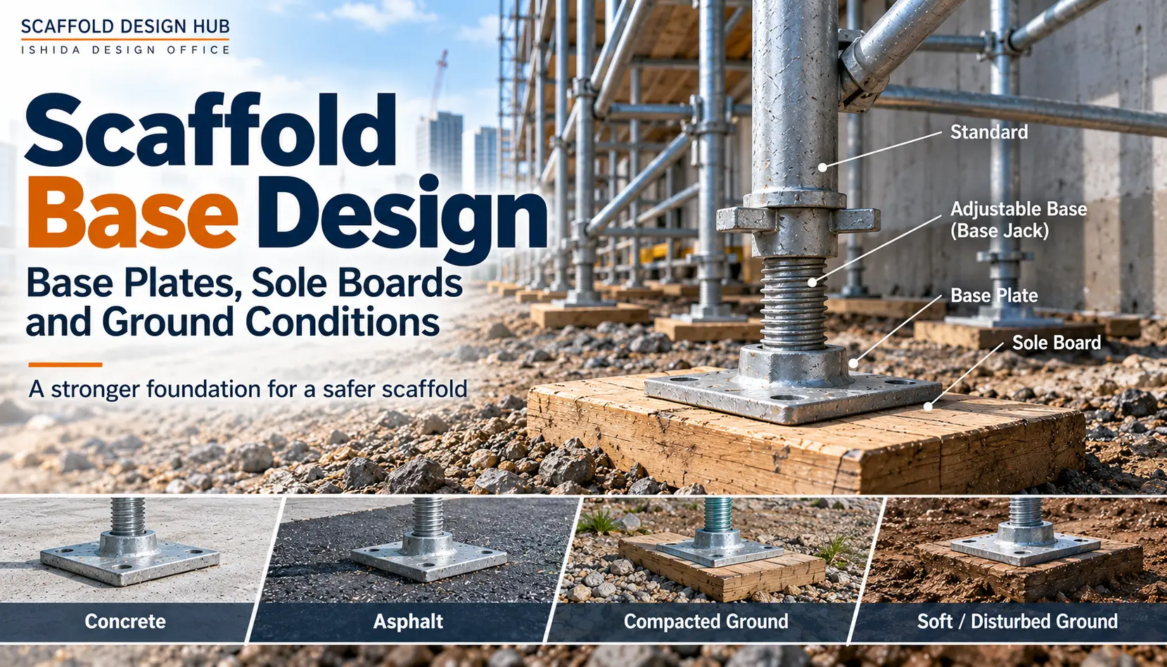
The standard transfers load into the base. The base plate helps distribute that reaction into the surface immediately below. Where a sole board is used, it spreads the load further into the supporting surface.
OSHA’s interpretation of its scaffold foundation requirements describes the same principle: mud sills distribute scaffold load over a larger area than the base plate alone, reducing the loading imposed on the ground beneath.
Safe Work Australia also describes sole boards and base plates as components that distribute scaffold loads to the supporting surface.
This is why base design should not stop at identifying a component. The complete path to the final supporting ground or structure needs to make sense.
What Does a Scaffold Base Plate Do?
A base plate provides a bearing interface between the scaffold standard or adjustable base and the surface below.
Its role includes helping distribute the reaction from the scaffold leg into the supporting surface immediately below and providing a stable interface at the bottom of the scaffold.
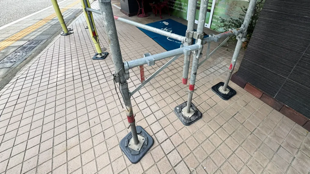
DO NOT ASSUME: A base plate does not automatically make weak ground strong.
If the surface beneath the plate cannot adequately carry the imposed load, increasing attention to the components above the plate does not eliminate the foundation problem.
The exact base components, dimensions, capacities and installation requirements depend on the scaffold system, manufacturer, project conditions and applicable local requirements.
Readers unfamiliar with the individual components may first want to review Scaffolding Parts Explained: Names, Sizes and Functions (Complete Guide).
What Does a Sole Board Do?
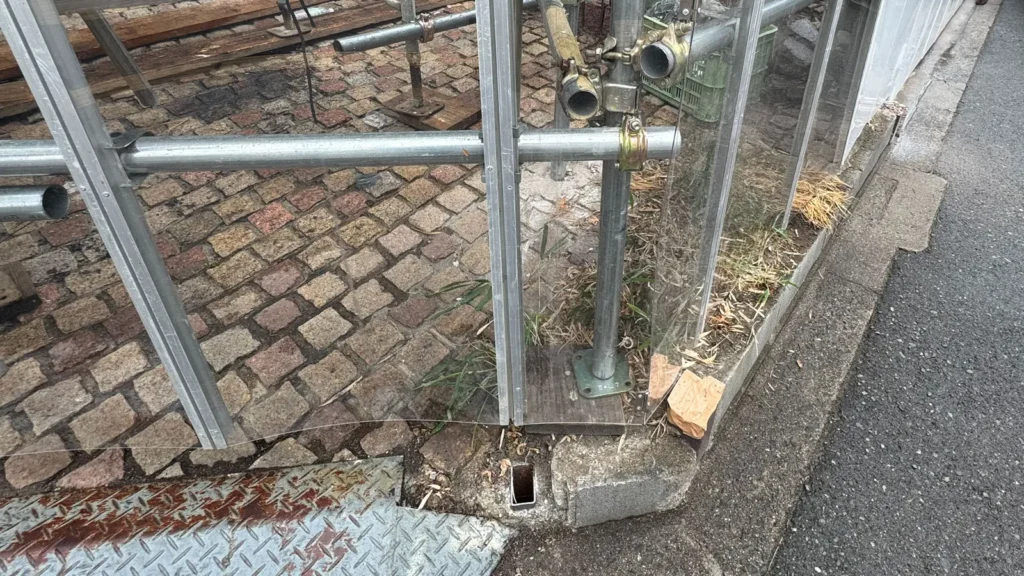
A sole board—also called a mud sill in some jurisdictions—is installed beneath a base plate where additional distribution of the scaffold load into the supporting surface is required.
Safe Work Australia notes that both sole boards and base plates may be required on less stable surfaces such as soil, gravel or fill, and that sole-board size varies with the supporting surface.
This last point is important.
DO NOT ASSUME: A sole board should not be selected simply because “this is the size we normally use.”
The supporting condition, imposed load and the behaviour of the sole board itself all matter. The board must perform its intended load-distribution function rather than merely being present beneath the scaffold.
This article deliberately does not provide a universal sole-board size. A single dimension cannot represent every scaffold system, load condition, material, ground condition or jurisdiction.
Base Plate vs Sole Board
The two components have related but different functions.
- A base plate receives the scaffold leg or adjustable base and distributes its load into the surface immediately below.
- A sole board can increase the effective load-distribution area between the base assembly and the supporting surface.
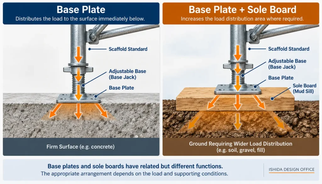
They should therefore not be treated as interchangeable terms.
A useful design question is not simply whether a sole board is shown. It is whether the proposed base arrangement is appropriate for the load and supporting conditions.
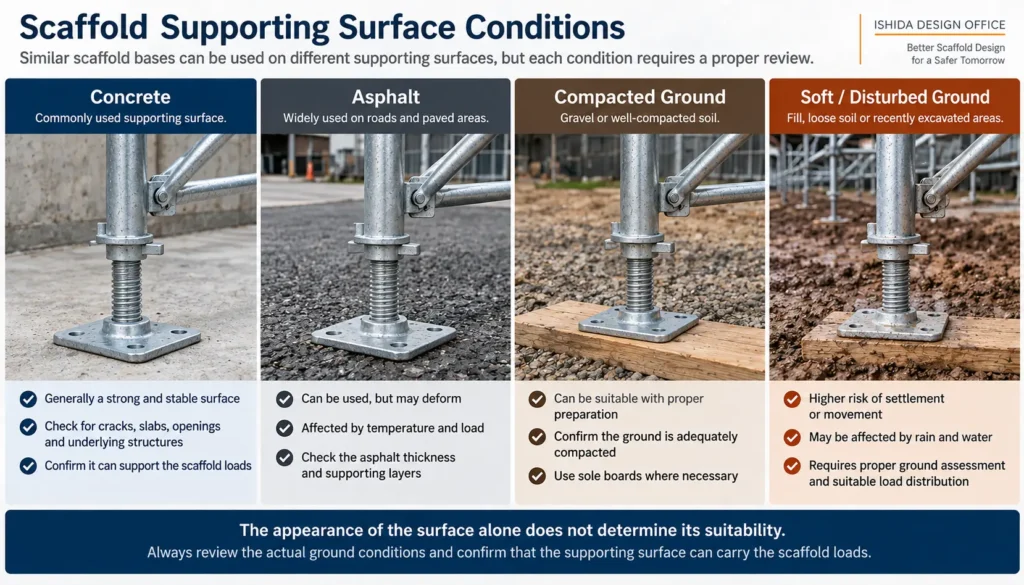
Ground Conditions Must Be Assessed
One of the easiest mistakes is to judge ground only by its appearance.
A surface can look hard while conditions below it are less reliable.
From a practical design perspective, relevant questions can include:
- What type of surface supports the scaffold?
- Is the ground natural, compacted or previously disturbed?
- Is fill present?
- Could the condition change after rain?
- Are there local soft areas?
- Is the scaffold close to an excavation, drain or underground feature?
- Is the surface level?
- Is the supporting condition consistent along the scaffold?
The objective is not to classify every site using appearance alone. It is to identify when the foundation assumption needs further information or specialist assessment.
Safe Work Australia’s scaffold inspection guidance asks whether the supporting structure has satisfactory strength, whether the scaffold is on solid ground, and—if it is on soft ground—whether sole boards properly distribute the load.
Soil and Soft Ground
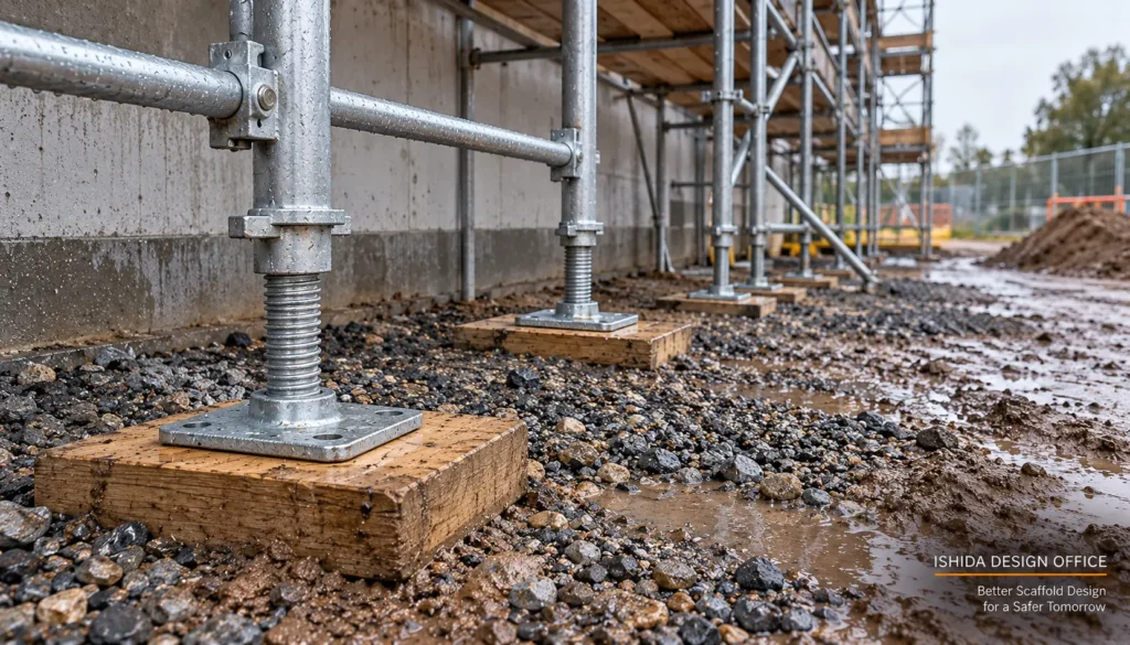
Soil conditions can vary considerably across even a relatively small site.
A hard-looking surface should not automatically be interpreted as evidence of adequate bearing capacity. Soft material, disturbed areas, water and local changes in ground condition can affect how the scaffold is supported.
Where bearing capacity is uncertain, appropriate competent or engineering assessment may be required under the relevant project and jurisdictional framework.
Fill and Previously Disturbed Ground
Backfilled or disturbed ground deserves particular attention because the visible surface does not necessarily reveal the condition below.
A scaffold designer may receive architectural drawings that show the building and surrounding levels but provide little information about how external ground was formed.
If the supporting condition is important and the information is missing, it should not simply be invented.
Additional site information, photographs, dimensions, ground information or project documentation may be needed.
Rain and Changing Ground Conditions
Foundation conditions are not necessarily static.
Rain and drainage can change the behaviour of some supporting surfaces. Safe Work Australia specifically identifies weather, particularly wind and rain, as factors to consider when preparing scaffold foundations.
This means that a base condition that appears acceptable during initial planning may require reconsideration if the supporting environment changes.
Scaffold Bases on Concrete
Concrete is often a much firmer supporting surface than soil or fill, but the word concrete should not end the design review.
Under OSHA’s U.S. interpretation, a concrete slab is considered a firm foundation for the purpose of determining whether a mud sill is required under its scaffold rule.
DO NOT ASSUME: This should not be interpreted as a universal engineering conclusion that every concrete surface, in every project, can support every scaffold load.
A designer may still need to understand what the concrete surface actually is.
- Is it ground-supported or suspended?
- Is there a basement, void or other structure below?
- Are there openings?
- Are there edges or local structural limitations?
- Could other loads already be acting on the supporting structure?
- Does the project engineer impose specific loading restrictions?
Safe Work Australia’s inspection guidance separately asks whether the supporting structure is in a safe condition, has satisfactory strength and is protected from overload or deterioration.
Do not replace “check the supporting condition” with “it is concrete, therefore it is fine.”
Scaffold Bases on Asphalt
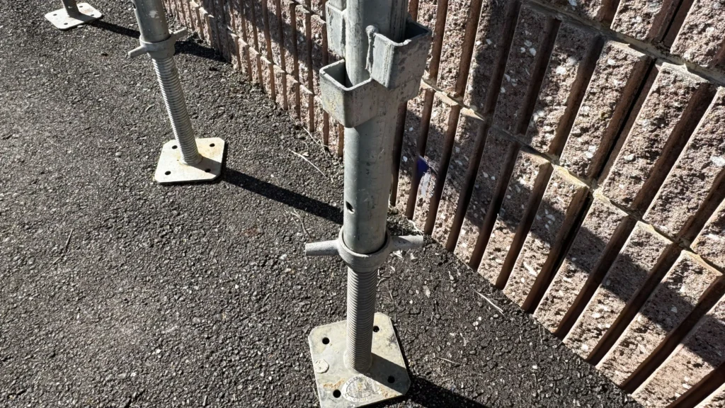
Asphalt should not automatically be treated as if it were structurally equivalent to concrete.
Its behaviour can depend on temperature, thickness, condition and the supporting layers beneath it. Concentrated scaffold reactions may also create local deformation depending on the actual circumstances.
OSHA’s official scaffold-foundation interpretation also explains that the ability of asphalt to support scaffold loads depends on the actual conditions and cannot be determined by a universal rule for every site.
OSHA — Foundation Requirements for Scaffolds
For that reason, the visible asphalt surface is only part of the support question.
The designer or responsible project team should consider whether sufficient information is available to justify the proposed base arrangement and whether additional load distribution or specialist review is needed.
Uneven and Sloping Ground
A scaffold still needs a suitable supporting arrangement when the surrounding ground is sloping or uneven.
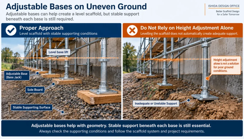
Adjustable bases are useful for establishing a level base lift within the permitted configuration of the scaffold system. Safe Work Australia notes that adjustable bases can be used on uneven surfaces for modular scaffold systems to provide a level base lift.
But adjustment capability should not be confused with unlimited foundation correction.
Adjustable Base Jacks Are Not a Universal Solution
A common mistake is to attempt to solve a difficult slope simply by extending individual base jacks until the scaffold appears level.
That addresses geometry, but it does not automatically resolve the supporting condition below each base.
- Is the base fully and properly supported?
- Is the sole board, where used, stable and level?
- Does the arrangement comply with the scaffold system requirements?
- Is the adjustable base within the manufacturer’s permitted configuration?
- Is there a risk of movement or local loss of bearing?
Manufacturer instructions and project-specific design requirements should therefore be checked rather than assuming that adjustment height alone solves the problem.
Hidden Conditions Below the Scaffold
Some foundation problems are not visible from the scaffold plan.
- Drainage channels
- Manholes
- Service trenches
- Underground utilities
- Basements or voids
- Covers over openings
- Recently backfilled areas
A plan may show a clear strip of ground beside the building while the actual support zone contains one or more of these features.
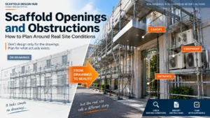
This is one reason site constraints should be reviewed as part of scaffold planning rather than after the scaffold geometry has already been fixed.
For a broader discussion of drawing development and site constraints, see How to Create Scaffold CAD Drawings That Actually Work on Site.
How Base Conditions Affect the Rest of the Scaffold
The foundation should not be viewed as an isolated detail.
Settlement or displacement at the base can affect scaffold geometry above it. Changes in vertical alignment can also influence how the overall scaffold configuration behaves.
This connects foundation design with other parts of scaffold planning, including dimensions, bracing and ties.
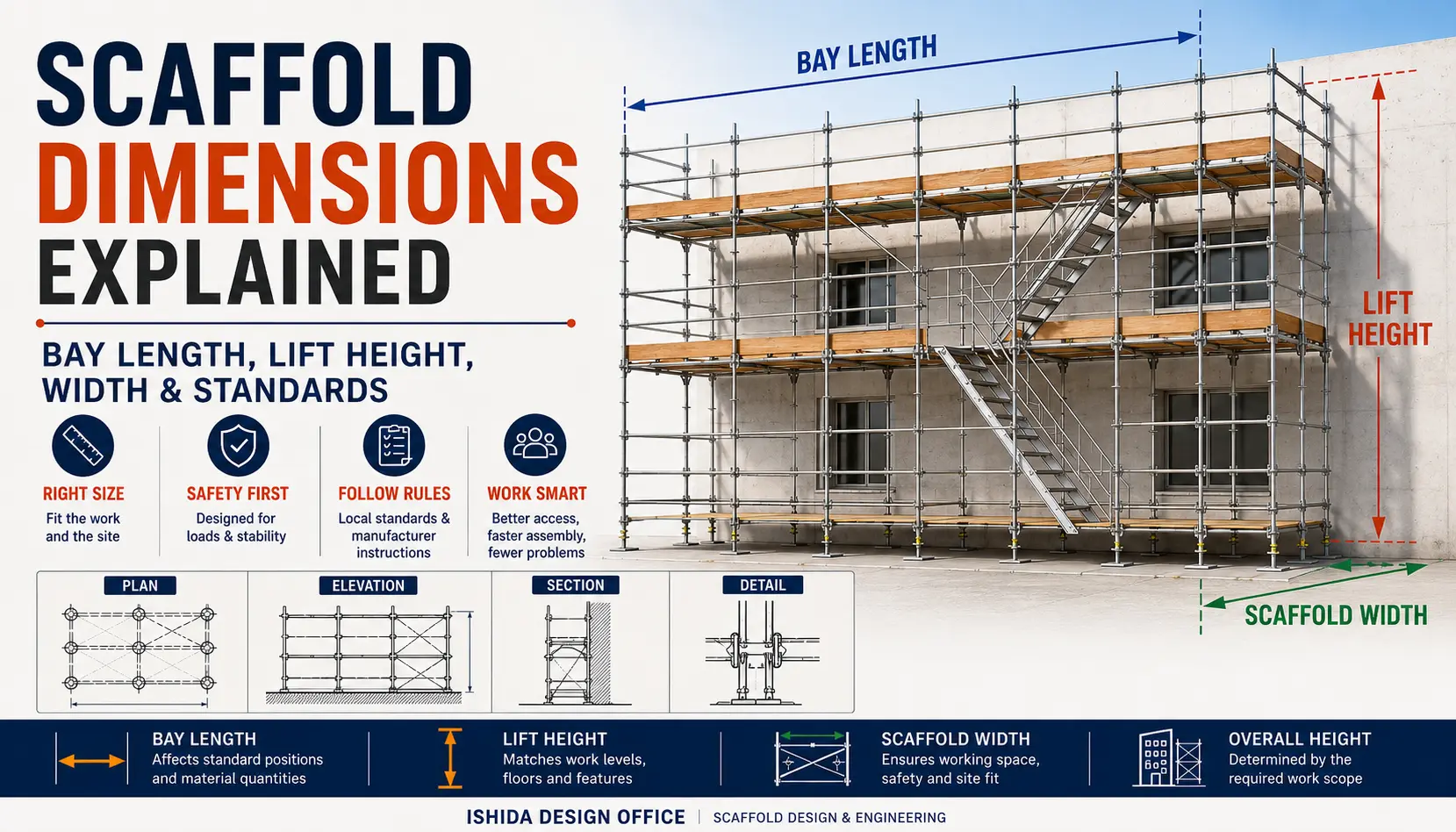
- Scaffold Dimensions Explained: Bay Length, Lift Height, Width & Standards
- Scaffold Bracing Explained: Types, Layout & Design Principles
- Scaffold Ties Explained: Types, Spacing & Layout
These subjects perform different functions, but they form part of one scaffold system.
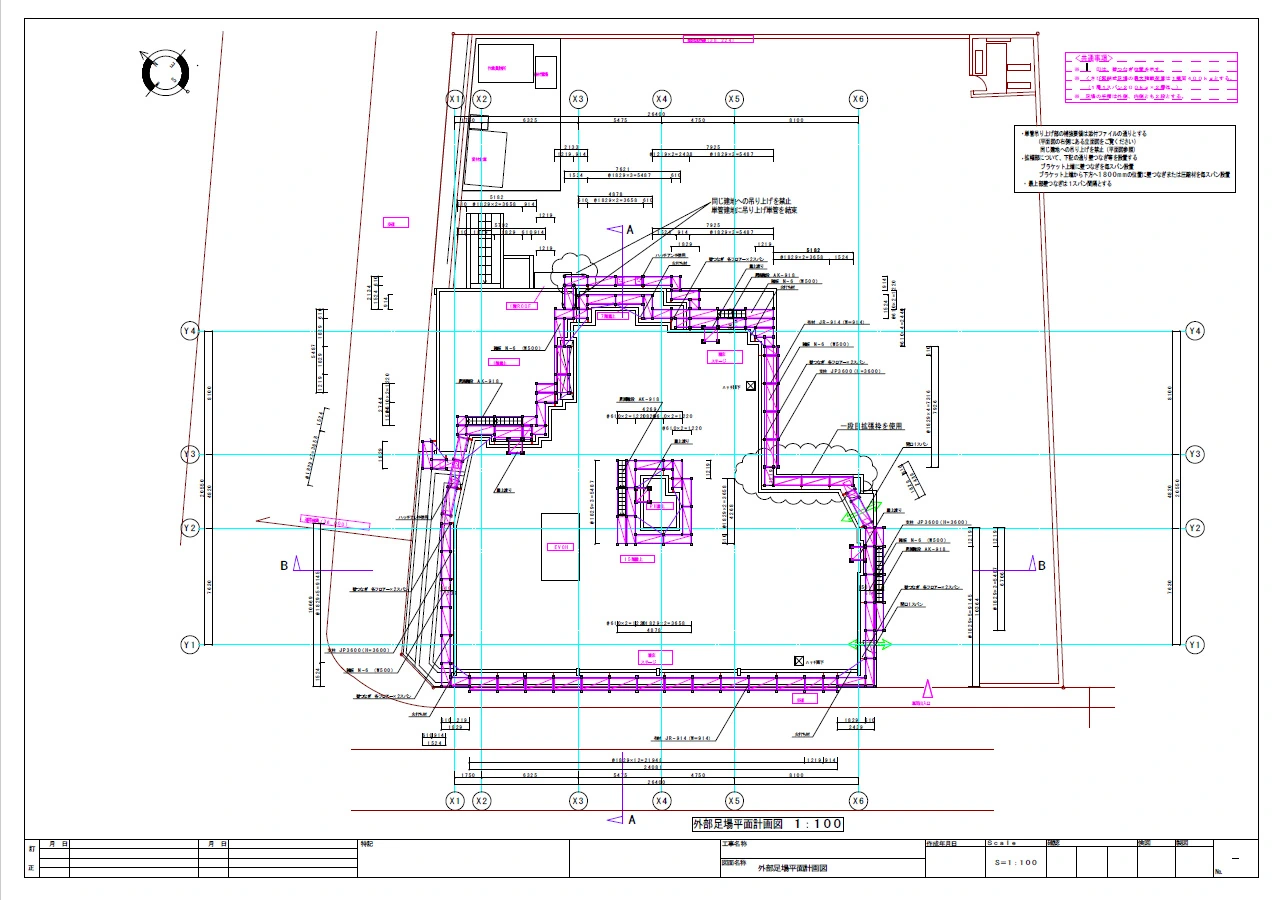
What Should Be Shown on Scaffold Drawings?
A scaffold drawing can describe the scaffold above ground in considerable detail while providing very little information about the conditions at its base.
That creates a communication gap.
Where foundation conditions are relevant to the design, the drawing or associated documentation should make the applicable assumptions and requirements clear enough for the project team to understand what has been designed.
Depending on the project, useful information may include:
- Supporting-surface type
- Base plate or adjustable-base arrangement
- Sole-board requirement where applicable
- Changes in ground level
- Locations requiring special consideration
- Known drains, openings or other constraints
- References to project-specific details or engineering information
- Notes identifying conditions that require verification before erection
The appropriate level of detail depends on the scaffold, project and responsibility structure. The objective is not to fill the drawing with unnecessary notes.
DRAWING CHECK: The objective is to prevent an important design assumption from remaining invisible.
Readers who need help interpreting scaffold plans, elevations, sections and details can refer to How to Read Scaffold Drawings: Plan, Elevation, Section & Details.
Common Scaffold Base Design Mistakes
1. Judging Ground Strength by Appearance
Mistake: Assuming that ground is adequate because it looks hard.
Why it matters: The visible surface may conceal fill, soft material, water-affected ground or other conditions.
Better approach: Confirm the relevant supporting condition and seek additional information where it cannot be established from the available documents.
2. Selecting Sole Boards by Habit Alone
Mistake: Using a familiar sole-board size simply because it has been used before.
Why it matters: Scaffold reactions, ground conditions and supporting arrangements vary.
Better approach: Treat the sole board as part of the load-transfer system and confirm that the proposed arrangement is appropriate for the actual conditions.
3. Assuming Concrete Means No Further Review
Mistake: Treating every concrete surface as an unlimited foundation.
Why it matters: A suspended slab, opening, structural edge, void or other project condition may change the support question.
Better approach: Identify what the scaffold is actually bearing on and verify the supporting structure where necessary.
4. Treating Asphalt Like Concrete
Mistake: Assuming asphalt behaves like a rigid concrete foundation.
Why it matters: Asphalt and its supporting layers can behave differently depending on actual conditions.
Better approach: Assess the real supporting system rather than relying on the surface material name.
5. Using Base-Jack Adjustment as the Only Response to a Slope
Mistake: Extending adjustable bases until the scaffold looks level without adequately considering the support beneath them.
Why it matters: Geometric adjustment does not automatically create stable bearing.
Better approach: Check both the permitted base configuration and the actual support condition.
6. Missing Drains, Manholes or Underground Features
Mistake: Reviewing only the visible surface.
Why it matters: The support zone may contain openings, voids, trenches or services.
Better approach: Compare drawings with available site information and identify areas that need verification.
7. Ignoring Changes Caused by Water
Mistake: Assuming the ground condition remains unchanged throughout scaffold use.
Why it matters: Rain and drainage can affect some supporting surfaces.
Better approach: Consider foreseeable changes in ground conditions and include appropriate inspection or review requirements.
8. Leaving Base Conditions Unclear on the Drawing
Mistake: Detailing the scaffold superstructure while leaving the foundation assumption undefined.
Why it matters: The designer and erection team may be working from different assumptions.
Better approach: Communicate relevant base conditions, limitations and verification requirements in the drawing or associated project documentation.
For other recurring drawing and planning issues, see 10 Common Scaffold Design Mistakes and How to Avoid Them.
A Practical Scaffold Base Review Checklist
Before finalising or reviewing a supported scaffold base arrangement, consider the following.
Supporting Surface
- ☑ What surface will actually support each scaffold line?
- ☑ Is it concrete, asphalt, soil, gravel, fill or another structure?
- ☑ Is the condition consistent along the scaffold?
- ☑ Is there evidence of disturbed or recently backfilled ground?
- ☑ Could water or weather change the condition?
Supporting Structure
- ☑ Is the scaffold on ground or on a structural slab?
- ☑ Are basements, voids or underground structures present?
- ☑ Are openings, edges, covers or trenches relevant?
- ☑ Is additional structural information required?
Base Components
- ☑ Is the correct base component specified for the scaffold system?
- ☑ Is a sole board or other load-distribution arrangement required?
- ☑ Is the proposed supporting arrangement level and stable?
- ☑ Are adjustable bases being used within applicable manufacturer/design requirements?
Site Constraints
- ☑ Are there drains or drainage channels?
- ☑ Are there manholes or service covers?
- ☑ Are underground services or trenches known?
- ☑ Is the scaffold close to an excavation?
- ☑ Are there slopes or level changes?
Drawing and Documentation
- ☑ Are important base assumptions shown or referenced?
- ☑ Are unusual foundation conditions identifiable?
- ☑ Are verification requirements clear?
- ☑ Does the drawing reflect available site information?
- ☑ Is further information required before the design is finalised?
This is a review checklist, not a substitute for project-specific engineering assessment, manufacturer instructions or applicable regulatory requirements.
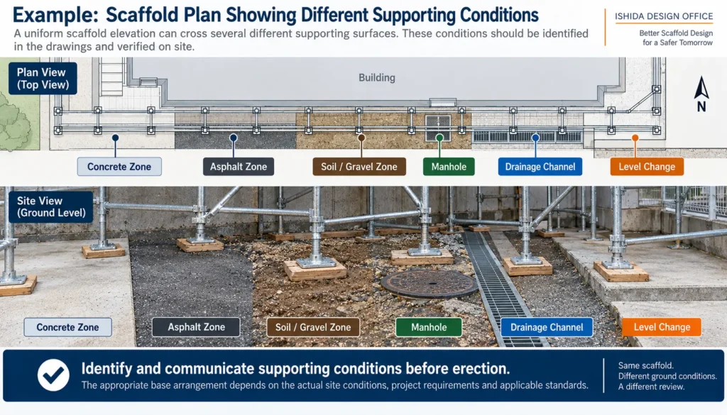
Illustrative Example: One Scaffold, Different Supporting Surfaces
Consider a scaffold elevation that continues along one side of a building.
On the drawing, the scaffold geometry appears uniform.
At site level, however, the first section stands beside a ground-supported concrete area. The next section crosses asphalt. Further along, landscaping work has created a filled-ground zone, and a drainage channel passes near another standard position.
The scaffold above these locations may look almost identical.
The foundation questions are not.
The design review should therefore identify the changes in supporting condition rather than assume that one base arrangement automatically applies to the entire elevation.
This is an illustrative example, not a description of a specific project.
A Practical Perspective from Scaffold Design
ISHIDA DESIGN OFFICE has been involved in scaffold and formwork-support design work in Japan since 1998.
One recurring lesson from long-term drawing and planning work is that site conditions cannot always be understood from the main building geometry alone.
Scaffold planning may also depend on boundaries, roads, adjacent structures, entrances, balconies, roofs, equipment, level changes and other physical constraints. When information needed for the design is missing, it is better to identify that gap and obtain additional drawings, photographs, dimensions or site information than to complete the design by assumption.
The same principle applies at the scaffold base.
In my scaffold design work in Japan, I have requested additional drawings, site photographs and dimensions from construction companies when the available information was insufficient to confirm ground conditions or the positions of manholes and drainage channels.
A scaffold arrangement may fit the building geometry shown on a plan, but that does not confirm the supporting conditions at every standard position. When information is missing, I identify what needs to be checked and request the relevant site information rather than treating an unverified assumption as a confirmed design condition.
A drawing can show the scaffold shape accurately while still leaving an important unanswered question: What is supporting it?
This practical perspective is also discussed more broadly in What 30 Years of Scaffold Design Has Taught Me.
FAQ
Does every scaffold need a sole board?
Not necessarily under every jurisdiction and supporting condition. For example, OSHA’s U.S. interpretation treats a concrete slab as a firm foundation for the purpose of its mud-sill requirement. Other surfaces and jurisdictions may be treated differently. The applicable regulation, scaffold system, manufacturer information and actual supporting conditions should be checked.
Is a base plate enough on soft ground?
A base plate alone should not be assumed to make soft ground adequate. The required load distribution depends on the actual support condition. Safe Work Australia notes that both sole boards and base plates may be required on less stable surfaces such as soil, gravel or fill.
Can scaffold base jacks compensate for sloping ground?
Adjustable bases can help establish a level base lift on uneven surfaces where permitted by the scaffold system, but they do not remove the need for adequate support beneath the base. Manufacturer and project-specific requirements still apply.
Is concrete always strong enough for scaffolding?
The presence of concrete alone should not be treated as proof that every supporting structure can carry every scaffold arrangement. The actual supporting structure, openings, voids, existing loads and project requirements may still need to be reviewed.
What happens if the scaffold ground settles?
Settlement can change the base levels and geometry of the scaffold and may lead to displacement or other stability concerns. This is why OSHA, for example, requires footings for supported scaffolds to support the loaded scaffold without settling or displacement.
Should ground conditions appear on scaffold drawings?
Where ground or supporting conditions affect the design, the relevant assumptions, base requirements or areas requiring verification should be communicated clearly through the drawing or associated project documentation.
Related Topics
- Scaffold Load Capacity Explained: Dead, Live and Environmental Loads — The natural next topic for understanding the loads that ultimately travel through the scaffold standards into the foundation.
- How to Create Scaffold CAD Drawings That Actually Work on Site — Connects base-condition assessment with practical drawing communication and site constraints.
- 10 Common Scaffold Design Mistakes and How to Avoid Them — Expands the foundation mistakes discussed here into a wider scaffold-design review.
- Scaffolding Parts Explained: Names, Sizes and Functions — Useful for readers who need more information about the components referenced in this guide.

Key Takeaways
- A scaffold base should be understood as a complete load path from the standard to the final supporting surface or structure.
- Base plates and sole boards perform related but different load-distribution functions.
- Ground should not be judged only by how hard it looks.
- Concrete, asphalt, soil, gravel and fill should not automatically be treated as equivalent supporting conditions.
- Adjustable bases can address level differences within their permitted use, but they do not eliminate foundation requirements.
- Drains, manholes, voids, underground structures and changing ground conditions can affect scaffold support.
- Important foundation assumptions should be communicated clearly in scaffold drawings or associated documentation.
Conclusion
Good scaffold base design begins below the scaffold, not at the first ledger.
The designer should understand how the load reaches the supporting surface, what that surface actually consists of, and whether the available project information supports the proposed base arrangement.
Base plates, sole boards and adjustable bases are important components, but none should be considered independently of the surface or structure beneath them.
When the supporting condition is uncertain, obtaining better information is preferable to designing from an assumption.
The next useful step is to connect these foundation conditions with the loads being transferred through the scaffold. See Scaffold Load Capacity Explained: Dead, Live and Environmental Loads for that wider load-path context.
Official References
Occupational Safety and Health Administration (OSHA), United States
29 CFR 1926.451 — General Requirements for Scaffolds.
Supports the article’s statements concerning supported-scaffold base plates, mud sills or other adequate firm foundations, and footing requirements relating to settlement and displacement.
OSHA 29 CFR 1926.451 — General Requirements
Occupational Safety and Health Administration (OSHA), United States
Scaffolding eTool — Supported Scaffolds, Base Section.
Supports the explanation of firm foundations, base plates, mud sills and stable scaffold bases.
OSHA Scaffolding eTool — Supported Scaffolds
Occupational Safety and Health Administration (OSHA), United States
Foundation Requirements for Scaffolds; Competent Person Qualifications for Assessing Foundations — Standard Interpretation, August 1, 2000.
Supports the explanation of load distribution through base plates and mud sills and the U.S.-specific discussion of concrete, asphalt and variable foundation conditions. This is an OSHA Standard Interpretation, not a separate regulation.
OSHA — Foundation Requirements for Scaffolds
Safe Work Australia
General Guide for Scaffolds and Scaffolding Work.
Supports the discussion of foundation preparation, dead and live loads, ground conditions, weather, sole boards, base plates and adjustable bases. This is Australian guidance; the currently hosted PDF is marked July 2014.
Safe Work Australia — Scaffolds and Scaffolding Work General Guide
Safe Work Australia
Guide to Scaffold Inspection and Maintenance.
Supports the practical checks relating to supporting structures, soft ground, sole boards, base plates and scaffold stability. This is Australian guidance; the PDF is marked July 2014.
Safe Work Australia — Guide to Scaffold Inspection and Maintenance
Last Verified: September 2026
Regulations, official guidance and manufacturer documentation may change. Always confirm the current requirements applicable to the project location, scaffold system and intended use.
This article is general technical information and is not a substitute for project-specific engineering, applicable law, contract documents, project specifications, manufacturer instructions or competent professional review.
About the Author
ISHIDA DESIGN OFFICE brings more than 25 years of practical experience in Japan, specializing in scaffolding design, temporary works planning, CAD drafting, quantity estimation, and construction support.
Drawing on experience from residential, commercial, and industrial projects, he shares practical insights that emphasize not only sound engineering design but also buildability, safety, and real-world jobsite application.
At Scaffold Design Hub, he combines practical experience from Japan with official guidance and technical resources from government agencies, manufacturers, and industry organizations around the world to provide reliable, practical information for construction professionals.
To learn more, visit the About page. For questions or project inquiries, please use the Contact page.